UNIVERSIDADE DA BEIRA INTERIOR
Engenharia
Pulsejet Engine Performance Estimation
(Versão Revista Após Discussão)
Andreia Sofia Moura Melo
Dissertação para obtenção do Grau de Mestre em
Engenharia Aeronáutica
(Ciclo de estudos integrado)
Orientador: Prof. Doutor Francisco Miguel Ribeiro Proença Brójo
iii
Dedication
To my beloved parents and my grandparents.
“Try not to become a person of success, but rather try to become a person of value.”
v
Acknowledgements
To my family, who always supported me unconditionally through all these years, especially my parents and my grandmother. They are the reason I came so far.
I would like to thank my supervisor, Professor Francisco Brójo, for all the help and guidance. A big thank you to my boyfriend Pedro Pereira, for believing in me and giving me motivation during the most stressful times.
I also want to thank all my friends from my hometown and those made in my academic life, especially Sara and Inês. They are a very important part of academic life and I will take them in my heart for the rest of my life.
Last but not least, a big thank to my dear friend Diogo Moura, for reviewing this document, but above all, for being a good friend.
vii
Resumo
Os motores pulsejet ganharam recentemente um novo interesse devido à sua simplicidade e possíveis aplicações em UAVs. Apesar de este tipo de motor apresentar muitas vantagens em relação a motores mais convencionais, tem diversos problemas de aplicação, nomeadamente na aviação civil, devido ao facto de ser um motor que produz muito ruído. Embora seja um motor com uma construção bastante simples, o seu funcionamento ainda não é perfeitamente compreendido, pelo que continuam a ser elaborados estudos de forma a melhorar o conhecimento relativamente à física envolta na sua operação. Este trabalho consiste numa aproximação numérica do funcionamento de um motor pulsejet sem válvulas. O objetivo é numa primeira fase proceder ao dimensionamento de um motor sem válvulas e, posteriormente, fazer a análise do seu desempenho para dois combustíveis assim como para diferentes caudais mássicos de combustível. Para elaborar o dimensionamento, foi feita uma rotina de cálculo baseada em dados de motores existentes e em equações referidas na literatura. O desenho do motor foi feito usando o software CATIA V5; a malha numérica foi criada no ANSYS Meshing; e, por fim, a análise foi feita no software ANSYS Fluent 16.2. Foi realizada uma simulação transiente em 2D. O modelo viscoso escolhido foi o Realizable 𝑘 − 𝜀; para as espécies foi escolhido o modelo de combustão sem pré-mistura (non-premixed model); e para o modelo de radiação foi selecionado o P1. Em relação às condições de fronteira, a entrada foi definida com base na pressão tal como a saída, a entrada de combustível foi então definida com base em três caudais mássicos: 0.04 kg/s, 0.06 kg/s e 0.1 kg/s. Foram usados dois combustíveis diferentes: propano e metano, de forma a avaliar se as diferenças apresentadas para os diferentes caudais mássicos de combustível eram comuns a ambos. Para o propano um caso adicional foi definido, sendo o caudal mássico de combustível de 0.12 kg/s. Diferentes variáveis foram analisadas para os sete diferentes casos: pressão, temperatura, frequência, velocidade, tração e a formação de poluentes. Os resultados obtidos são similares para os dois combustíveis, as variáveis apresentam o mesmo comportamento com a variação do caudal de combustível, à exceção da frequência de funcionamento. Quando é usado o metano, a frequência aumenta com o aumento do caudal de combustível, no entanto, para o caso do propano o mesmo não se verifica. Relativamente ao dimensionamento, este foi elaborado em função de uma tração desejada de 6 kg, todavia, a tração máxima obtida foi de 2.5 kg.
Palavras-chave
Pulsejet; pulsejet sem válvulas; dimensionamento; propano; metano; caudal mássico de combustível; ANSYS Fluent
ix
Abstract
Pulsejet engines have recently come into the spotlight due to its simplicity and its possible application in UAVs. Even though this type of engine has many advantages over the conventional types, it still has many problems for its application, as in civil aviation due to its extreme noise. Although having a very simple construction, its operation is not completely understood, so studies continue to be made in order to have a better knowledge of the physics behind its operation. This work investigates a valveless pulsejet operation in a numerical approach. The objective includes a sizing of a valveless pulsejet and analyse the pulsejet performance with two different fuels and for different fuel mass flows. For the sizing it was done a calculation procedure based on data of existing engines and equation reported in the literature. The pulsejet was designed using the software CATIA V5; numerical mesh was created in ANSYS Meshing; and the analysis in ANSYS Fluent 16.2. It was performed a 2D transient simulation. The viscous model is Realizable 𝑘 − 𝜀, for species non-premixed combustion model was selected and radiation model is P1. Inlet was defined as a pressure inlet and outlet as a pressure outlet, fuel inlet was defined as mass flow inlet with three different fuel flow to be analysed: 0.04 kg/s, 0.06 kg/s and 0.1 kg/s. Two fuel where used: propane and methane, in order to evaluate whether the differences reported for the different fuel mass flow were also observed with other fuels. For propane an additional case was defined, being the fuel mass flow of 0.12 kg/s. Diverse variables were computed for the seven cases: pressure, temperature, frequency, velocity, thrust and formation of pollutants. The results obtained are similiter for the two fuels, the variables have the same behaviour with the variation of the fuel flow except for the operating frequency. For methane the frequency increases with increasing fuel flow, for propane, however, this is not verified. In the relation to the sizing, this was elaborated as a function of the desire thrust of 6 kg, nevertheless the maximum thrust obtained was of 2.5 kg.
Keyword
xi
Contents
1 Introduction ... 1
1.1 Motivation and goals ... 1
1.2 Document structure ... 2
1.3 Historical background ... 3
1.4 Related work ... 6
2 Theoretical background ... 9
2.1 Types of pulsejet engine ... 9
2.1.1 Valved pulsejet ... 9
2.1.2 Valveless pulsejet ... 10
2.2 Advantages and limitation of pulsejet ... 11
2.2.1 Valved vs Valveless pulsejet ... 12
2.3 Thermodynamic cycle ... 12
2.4 Kadenacy Effect ... 15
2.5 Acoustic Theory ... 15
2.6 Pulsejet frequency ... 16
2.7 Pulsejet components ... 18
2.8 Valveless pulsejet design ... 19
3 Numerical Modelling ... 21 3.1 Governing equations ... 21 3.2 Models ... 23 3.2.1 Turbulence model ... 23 3.2.2 Species model ... 24 3.2.3 𝑁𝑂𝑥 formation ... 25 3.2.4 Radiation ... 26
3.3 Near wall treatment ... 27
4 Methodology ... 29
4.1 Sizing procedure ... 29
xii
4.2 Generation of numerical mesh ... 34
4.3 Problem setup ... 35 4.3.1 Boundary conditions ... 35 4.4 Solution ... 36 4.4.1 Solution methods ... 36 4.4.2 Solution controls ... 38 4.4.3 Monitors ... 39
4.4.4 Solution initialization and calculation set-up ... 39
4.5 Thrust calculation ... 40 5 Results ... 43 5.1 𝒚 + analysis ... 43 5.2 Propane ... 44 5.3 Methane ... 48 5.4 Emissions analysis ... 51 5.4.1 Carbon monoxide ... 51 5.4.2 Carbon dioxide ... 52 5.4.3 Nitrogen oxides ... 53
5.5 Combustion chamber pressure vs thrust ... 54
5.6 Frequency ... 56
6 Conclusion and future work ... 59
6.1 Conclusion ... 59 6.2 Future work ... 60 Bibliography ... 62 Appendix A ... 66 Appendix B ... 68 Appendix C ... 70 Appendix D ... 72
xiii
Figures List
Figure 1 - Marconnet's pulsejet engine... 3
Figure 2 - Schmidt Argus V1 pulsejet engine ... 3
Figure 3 - Escopette pulsejet engine ... 4
Figure 4 - Lockwood Hiller pulsejet engine ... 5
Figure 5 - Boeing pulse ejector thrust augmenter ... 6
Figure 6 - Valveless pulsejet operation principle ... 10
Figure 7 - Lenoir thermodynamic cycle. ... 12
Figure 8 - Humphrey thermodynamic cycle. ... 15
Figure 9 - Representation of a thrust augmentor. ... 19
Figure 10 - Schubert in-line pulsejet. ... 20
Figure 11 - Chinese CS pulsejet. ... 20
Figure 12 - U-shaped pulsejet. ... 20
Figure 13 - Non-premixed combustion. ... 24
Figure 14 - Near wall treatment. ... 28
Figure 15 - Pulsejet combustion chamber design. ... 32
Figure 16 - Pulsejet isometric view. ... 34
Figure 17 - Initial pressure distribution. ... 40
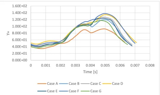
Figure 18 - y+ variation during a cycle. ... 44
Figure 19 - Temperature contour for case A. ... 45
Figure 20 - Temperature contour for case B. ... 45
Figure 21 - Temperature contour for case C. ... 47
Figure 22 - Temperature contour for case D. ... 47
Figure 23 - Temperature contour for case E. ... 49
Figure 24 - Temperature contour for case F. ... 49
Figure 25 - Temperature contour for case G. ... 50
Figure 26 - Contours of CO concentration for case G. ... 51
Figure 27 - Contours of CO2 concentration for case G. ... 52
Figure 28 - Contours of NOx concentration for case G. ... 53
Figure 29 - Combustion chamber pressure vs thrust for case C. ... 54
Figure 30 - Combustion chamber pressure vs thrust for case D. ... 55
Figure 31 - Combustion chamber pressure vs thrust for case E... 55
Figure 32 - Combustion chamber pressure vs thrust for case F. ... 56
Figure 33 - Combustion chamber pressure vs thrust for case G. ... 56
Figure 34 - Computational vs calculated frequency for propane. ... 57
Figure 35 - Computational vs calculated frequency for methane. ... 57
xiv
Figure 37 - a) Mesh overview b) approximate view of the inflation layer ... 68 Figure 38 - Air mass flow rate for propane. ... 72 Figure 39 - Air mass flow rate for methane. ... 72
xv
Table List
Table 1 - Pulsejet thrust and combustion chamber volume. ... 29
Table 2 - Pulsejet engines parameters. ... 30
Table 3 - Pulsejet mean areas and diameters. ... 31
Table 4 - Pulsejet engine lengths. ... 31
Table 5 - Diameter ratio. ... 32
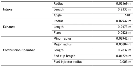
Table 6 – Pulsejet dimensions. ... 33
Table 7 – Mesh independence study. ... 35
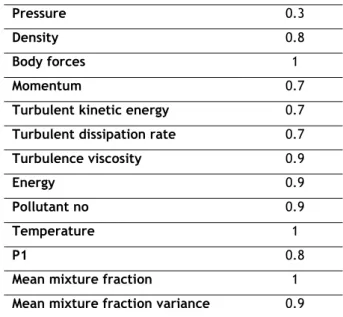
Table 8 – Under-relaxion factors. ... 38
Table 9 – Obtained results for case A. ... 45
Table 10 – Obtained results for case B. ... 46
Table 11 – Obtained results for case C. ... 47
Table 12 – Obtained results for case D. ... 48
Table 13 – Obtained results for case E. ... 49
Table 14 – Obtained results for case F. ... 50
Table 15 – Obtained results for case G. ... 50
Table 16 – Results of CO formation per cycle. ... 52
Table 17 – Results of CO2 formation per cycle. ... 53
xvii
List of Acronyms
CFD Computational Fluid Dynamics CPU Central Process Unit
NASA National Aeronautics and Space Administration PDE Pulse Detonation Engine
PDF Probability Density Function PETA Pulse Ejector Thrust Augmenter
PISO Pressure-Implicit with Splitting of Operators UAV Unmanned Aerial Vehicles
USAAF United States Army Air Force VTOL Vertical Take-Off and Landing
xix
Nomenclature
𝑎 Absorption coefficient [-] 𝐴 Cross-section area [m2] 𝐴𝑚 Mean area [m2] 𝑐 Speed of sound [m/s] 𝐶𝑝 Heat capacity at constant pressure [-]𝐶𝑣 Heat capacity at constant volume [-]
𝐷 Diameter [m] 𝐷𝑚 Mean diameter [m] 𝐸 Energy [J] 𝑓 Frequency [Hz] 𝐹 Thrust [kg] 𝐺 Incident radiation [-] 𝐻 Height [m]
𝑘 Turbulence kinetic energy [m2/s2]
𝐿 Length [m]
𝑚 Mass [kg]
𝑚̇ Mass flow [kg/s]
𝑝 Pressure [Pa]
𝑃𝑎𝑏𝑠 Absolute pressure [Pa]
𝑃𝑔𝑎𝑢𝑔𝑒 Gauge Pressure [Pa]
𝑄 Heat [J]
𝑞𝑟 Radiation flux [W/m2]
𝑅 Specific gas constant [J/kg.K] 𝑆𝐺 User-defined radiation source [-]
𝑇 Temperature [K]
𝑈 Internal energy [J]
𝑣 Velocity [m/s]
𝑉 Volume [m3]
𝑊 Work [J]
xx
Greek letters
𝑣⃗ Global velocity vector [m/s]
𝜇𝑡 Turbulent viscosity [m2/s]
𝜎𝑘, 𝜎𝜀 Constants of turbulence model [-]
𝜎𝑠 Scattering coefficient [-]
𝜏̿ Stress tensor [Pa]
𝜂 Efficiency [-]
𝜌 Density [kg/m3]
𝜎 Stefan-Boltzman constant [W/m2K4]
ϒ Heat capacity ratio [-] 𝜀 Rate of dissipation [m2/s3] 𝜇 Molecular viscosity [N/(ms)]
Subscript
𝐶𝐶 Combustion chamber 𝐶𝑢𝑝 End cup 𝐸𝑥 Exhaust pipe 𝐼𝑛 Intake pipe1
Chapter 1
Introduction
1.1 Motivation and goals
Nowadays, the UAV technology is constantly improving, as this type of aircraft has created a big impact in our culture in the past years and it is expected that in a closer future the advance of this technology will bring big changes. Given this, so that might happen it is necessary to make even greater efforts, as well as to improve older technologies and find new ones. In what concerns propulsion systems, there are many types of engines that could be used in UAVs. Depending on the type of mission for which it may be designed, many variables must be considered, and it ought to be selected a propulsion system more suitable for whichever mission the UAV is designed for. Currently the main investigation is being focused on implementing clean energy, however, the types of power sources available are not sufficiently developed yet. Electrical batteries don’t have the power density needed for some specific missions and these electrical systems still need to be coupled with the conventional power sources: air-breathing systems. Older technologies are therefore still necessary, and so is the investigation about them. It is important to investigate whether they can be improved or if there will be benefits when combining them with new technologies that have been developed.
One of these technologies which isn’t widely used is pulsejet engines. Major developments of pulsejet engines started in the beginning of the 20th century, but after the World War II the
researches and developments of this kind of engine significantly decreased, as turbo machines took the spotlight for their applications in aviation. Recently, however, aviation has once again turned its head to pulsejet engines, as these are a great choice for UAV applications, given the fact that they have a massive advantage when compared with other engines: the simplicity of its construction. This type of engine can be made with few or no moving parts and is able to run continuously, resulting in a system which is of economical construction. Nonetheless, pulsejet engines are very noisy and produce a lot of vibration, but this does not become a constraint for its use in UAVs.
Despite being an engine with many years of history, its operation is still not completely understood. Therefore, it is necessary to study the behavior of this type of engines under different conditions. The motivation for doing this work is to study the simplicity of an old propulsion system and its performance under different variables, and posteriorly report the consequent effects in the engine operation.
2
Primarily, the main goal is developing a calculation routine to perform an initial sizing of the engine. Then, an CFD analysis will be taken in order to verify if the initial sizing leads to a functional engine.
An important step to take firstly is an intensive research of technical literature to gather relevant information about pulsejets. This review will be extremely helpful to understand the operation principles of this type of engine.
Secondly, for the sizing, is necessary to find the plans of existing engines and make a statistical study to determine the relation between the different parts of the engine and then obtain a draught of the design. After this, using software Ansys Fluent 16.2 an evaluation of the engine performance will be made. In addition, different parameters in performance of the engine will be evaluated for different fuels and different fuel mass flow rates.
1.2 Document structure
The first chapter is about the purpose of elaborating this master’s thesis and the explaining of the motivation that led to this work. In this chapter it is also described the goals behind this investigation and what is supposed to be achieved through it. A historical review is presented in order to understand the evolution of these engines and their application through the decades. It is also included a small review of the most relevant works for this theme.
Second chapter is a theoretical background: an overview of the pulsejet operation. In this chapter is explained the physics behind its functioning.
In third chapter an introduction is made to the theory behind the numerical modelling. The governing equations are presented, and the models used in this simulation, as well as the near wall modelling, are clarified. It is also described the procedure for the thrust calculation. Fourth chapter is the parametric study: here it is described the method used to do the sizing of the engine and the numeric model. Are explained all the process that led to the sizing and the final dimensions of the engine presented. The mesh independence study, the boundary conditions and the solution methods are included as well.
Fifth chapter contains the presentation and discussion of the results obtained. It is explained what was expected and what is new, there is also reference to possible mistakes that might have happened. The final goal is to compare these results with other reported in the literature. In the final chapter it is presented the ultimate considerations and the conclusion that can be withdrawn with the accomplishment of this work. Proposals for future work in the field are taken in consideration.
3
1.3 Historical background
References to pulse combustion and its applications date back to late 17th–early 18th centuries
and the contributions of Huygens and Allen are noteworthy. These references generally deal with the complex fluid-thermo-chemical processes that control the operation of various pulse combustors and oscillating flames, and pulse combustion applications. Major developments of pulse combustion applications started in the beginning of the 20th century and led to the
development of the Esnault-Peltrie, Holzworth and Karavodine gas turbines that utilized a pulse combustion process to burn the fuel [1].
In 1906, Russian engineer Vladimir V. Karavodin found a way to evaluate the frequency, stability and thrust produced for different diameters and lengths. A year later, based on his research, he successfully builds a working pulsejet engine which was a high velocity pulsed gas jet generated by a cyclic combustion of a liquid hydrocarbon fuel/air mixture [2].
Marconnet developed the first valveless pulsejet in 1909, although his patent was for a valved pulsejet engine (see fig. 1). His project is composed of an inlet diffuser, combustion chamber and a long outlet diffuser to direct most of the combusted mixture through exhaust pipe rather than through intake [3].
In 1931 German Paul Schmidt patented a valved pulsejet and eight years later his technology was manufactured by Argus Company. This engine, Schmidt Argus V1 pulsejet (see fig. 2), is the most famous pulsejet engine due to its use to power the Vergeltungswaffe, better known by V-1 flying bomb, which was extensively used in Wold War II.
Figure 1 - Marconnet's pulsejet engine [3].
4
After the World War II, the United States created Project SQUID as an effort to improve pulsejet and rocket engines, this project was run by the Office of Naval Research [4]. In 1944 USAAF (United States Army Air Force) and America industry developed Jet Bomb 2, more informally known as “Thunderbug”, whose first successful launch was on 5th June 1945. The US Navy also
built its V-1 variant, the KUV-1 Loon. Many other countries also tried to make their own variant of V-1 flying bomb. During 1940s, USSR and Japan produced their derivatives and copies of the flying bomb, and in the 1950s, the French developed a target drone named “Arsenal 5.501” which was similar to the V-1 but had twin tail fins and radio control.
Lt. William Schubert of the US Navy designed his valveless pulsejet engine in the beginning of 1940s. His project had two improvements over Marconnet’s: the design of the combustion chamber and the intake geometry. The entry of the combustion chamber has abrupt change of the area which produces high turbulence and allows a better mixture of the air and fuel. For the intake, Schubert created a new geometry that allowed the exhaust gas to remain in the combustion chamber until the pressure inside falls below atmospheric [5].
In 1950, Bertin and the SNECMA Corporation developed Ecopette Pulsejet (see fig. 3), this was considered the best performing engine to date. Among its improvements, we highlight the presence of a recuperator, which is a curved tube mounted at some distance from the intake. In admission of fresh air, the engine breathes through the opening between the intake and the recuperator. During the expansion, the hot gases are expelled through the exhaust pipe, although a small portion of them are expelled through the intake. In this phase of the combustion cycle the recuperator acts as a part of the engine turning the hot flow backwards and increasing the thrust. The flow, in the intake phase, is negatively affected by the presence of the recuperator, however, its presence compensates in exhaustion phase by reducing the effective length of the engine and so improving the efficiency of the engine. Another improvement is in the exhaust pipe which until now was a straight pipe, in this model it is, however, divided to increase the area of the section. As can be seen in the figure below, the engine exhaust pipe is composed by two straight and two conical sections and the transition point between the different sections causes a reflection of the pressure waves. After this reflection the pressure wave turns as a rarefaction wave, which can be considered a negative pressure wave, and this phenomenon will improve the vacuum formed in the combustion chamber, thus increasing the aspiration of fresh air during the intake phase [3] [6].
5 In the following years, interest in pulsejet technology strongly decreased, as developments in turbojets brought more attention, even so some research continued to be done concerning pulsejet engines.
Between 1950 and 1960 the Lockwood Hiller engine appeared (see fig. 4), a U-shaped valveless pulsejet. This engine can be seen has the successor of the Ecrevisse engine, developed by SNECMA, and may be also considered the most effective pulsejet in history. One particularity of this engine is the fact that it does not have any straight part, the section area changes constantly. This non-uniform cross section brought some improvements when compared to the engines developed so far. Among such improvements are “easier engine starting, greater permissible range of variation in the rate of fuel delivery accommodated by the engine, and higher ratio of thrust and air-handling capacity of the engine per unit volume thereof” [7].
Another pulsejet model is the Thermojet, that is a valveless pulsejet designed by John A. Melenric [3]. The design of this is very similar to other ones that appeared at that time except that this one had two (could even had four) intakes parallel to the tailpipe, allowing the intakes to be shorter.
More recently, Boeing patented a Pulse Ejector Thrust Augmenter (PETA) – see Fig. 5, through which proposes the use of valveless pulsejet engines for vertical take-off and landing aircraft (VTOL). Each pulsejet includes a combustion chamber having an upstream inlet port joined to an inlet diffuser, and a downstream exit port joined to a discharge nozzle. Each pulsejet discharges into an ejector to increase net thrust. Each ejector includes an augmentor cell. This design was patented in the beginning of the 21st century, however, to the date no major
developments have been done [8].
6
In the last years pulsejet engines earned a new interest, particularly for its use in UAV propulsion. The main researches have focused on PDE (pulse detonation engines): PDE works on detonation of the fuel air mixture (this is a supersonic combustion), while conventional propulsion engines use deflagration, which is a subsonic combustion. Although this type of engine is attractive for its structural simplicity, its operation is not that simple. The high noise levels remain a problem that have not been overcome and are the main impediment of their use.
1.4 Related work
The majority of the studies undertaken more recently are focused in valved pulsejet engines. The attractiveness behind pulsejet engines depends upon the fact that they are very easy to build on small scales. They can be constructed into low-cost micro-scale propulsion devices for use in many new applications such as UAVs. However, attempts to design and build a valved 15 cm pulsejet were unsuccessful due to the reed valves, so traditional valved inlet was replaced with a valveless inlet [9]. The smallest valveless pulsejet reported is by Geng et. al. and has 8 cm [10].
In terms of sizing, there is no calculation routine found in literature, although there are studies that present guidelines on how to do a proper sizing. Based on observations, the exhaust tube internal diameter should be half the maximum combustion chamber’s internal diameter. And, the internal diameter of the intake tube should be around three fourth of the exhaust’s internal diameter. Kudesia and Bisen also state that valveles pulsejet are highly dependent on the way the fuel is delivered and on the location of the fuel stream [11]. It is important to have an appropriate sizing of pulsejet’s components, since it will influence its operation.
A report of a 50 cm valveless pulsejet shown that with increasing intake tube diameter both frequency and exhaust temperature at outlet increased, while inlet temperature decreases [2].
7 The lengths of intake and exhaust tubes are also important, the operation frequency increases with decreasing exhaust tube length or with increasing intake tube length [9] [2]. In the study of 8 cm valveless pulsejet some conclusions relatively to the fuel mass flow rate are stated. For rearward-facing inlet, the operation frequency and peak pressure increases with increasing fuel mass flow. Also, there have been comparisons between the thrust produced in a forward and rearward-facing inlet. As expected, less thrust was measured in the configuration with a forward-facing inlet [10].
9
Chapter 2
Theoretical background
2.1 Types of pulsejet engine
Pulsejet is the simplest type of jet engine, it can be made with few or no moving parts and can run statically. It is basically constituted by cylindrical and hollow sections. Its simplicity makes engines easy to manufacture and cheap to produce. The intake of air is intermittent, and this results in a pulsating combustion. A pulsating combustion is a burning process through acoustic oscillations: the fuel and air are submitted to compression and decompression rising the mixture efficiency and consequently the combustion reaction.
Based on the valves, there are two types of pulsejet engines: • Valved pulsejet;
• Valveless pulsejet.
2.1.1 Valved pulsejet
The valved type has a set of one-way valves that controls the admission of fresh air through the intake. To start the engine, it is necessary the admission of compressed air, for which the valves must be open. If the pulsejet is stagnant and there is no relative air velocity it is necessary to provide compressed air by an external equipment, but if it is moving the air dynamics pressure provides the necessary air compression. The fuel can be mixed with air directly in the intake or it can be injected into the combustion chamber (it is either a gas or liquid aerosol) and, after the mixture, the ignition is made using a spark plug. When the combustion occurs the pressure inside the combustion chamber increases shutting the valves. With the valves closed, the combustion gases have only one way to be expelled: through the exhaust pipe, producing forward thrust. Due to inertia of the exhaust gases, the pressure in the combustion chamber strongly decreases, allowing the valves to open again and admit a new portion of fresh air and a new cycle begins. In this new cycle the use of a spark plug to start ignition is not necessary, as the mixture is ignited by the residual heat from the previous cycle. The cycle frequency of valved pulsejet depends mainly on the length of the engine: the smaller it is, the bigger the frequency [12].
10
2.1.2 Valveless pulsejet
Valvess pulsejet is the simplest type of engine, there is no moving parts and both admission and exhaustion are controlled by its geometry. It can also be designated as aerodynamic valved pulsejet, acoustic-type pulsejet or intermittent ramjet [5]. This type of pulsejet usually has the intake and the exhaust pipe in the same direction. As in the valved pulsejet the cycle begins with the intake of compressed air and fuel. To start the engine the use of a spark plug is necessary to ignite the fuel air mixture. Once the engines start, the spark plug become unnecessary since the residual heat in the combustion chamber ignites the mixture, as it happens in valved engine. The combustion increases the temperature and pressure in combustion chamber, causing the gases to expand and causing a compression wave which travels through the intake and exhaust pipe. The pressure wave reaches the end of the intake pipe first and then it is reflected in the opposite direction as a rarefaction wave. Although this rarefaction wave is weak it can reserve the gases and admit fresh air into the intake pipe. When the compression wave reaches the end of the exhaust pipe, it is also reflected as a rarefaction wave, this one takes more time to happen because the exhaust pipe is longer. Rarefaction wave travels back to the combustion chamber but, due to inertia, the hot gases continue to be expelled through the exhaust pipe. The momentum of the gas pulse assists the hot gases reversing direction. When the rarefaction wave arrives in the combustion chamber the pressure falls below the atmospheric and this permits the intake of fresh air. At this point the exhaust gas continues flowing out through the exhaust pipe and the rarefaction wave is reflected from the end of the combustion chamber. After this reflection the flow in the exhaust pipe start to reverse and the rarefaction wave is reflected again and turns back to the combustion chamber as a compression wave. At this point, the admission of fresh air is slowed down allowing the combustion to start and the cycle repeats. It is important to notice that, inside the pulsejet, the wave travels at the speed of sound, though due the temperature this speed is higher that it would be in normal conditions [13].
The movements of the gases may be explained by the Kedenacy Effect and the Acoustic Theory and both will be clarified further ahead (see Fig. 6).
11
2.2 Advantages and limitation of pulsejet
The first thing about pulsejet engine that excited the researchers was its self-sustaining operation, which is a peculiar pulsating combustion propriety. The combustion is intermittent and does not occur at a constant pressure such as in most of jet propulsion systems. The succession of explosive pulses causes a pressure increase inside the combustion.
Pulsejet is the only jet engine that shows a net pressure gain between the intake and the exhaust. The exhaust pressure is higher than the intake pressure and this happens without wasting the power generated by combustion. This pressure gain, which is about 5%, improves the overall efficiency, however, it is difficult to use this gain for propulsion. A way to improve the potential of pulsejet engine is to use them as a combustor for a turbine engine, because its pressure gain will be multiplied in a high-pressure environment [14].
These engines can be made in different sizes with different thrust outputs, which is an economical advantage in the field of miniature propulsion. It has a very high thrust-to-weight ratio.
A major advantage is its simplicity: it has been already mentioned that pulsejet have little or no moving parts, which makes it easy to maintain and cheap to produce. It has also a great heat capacity, it uses atmospheric oxygen and cheap fuels. They can run statically and do not need to have air forced into the inlet by forward motion. If compared with traditional constant pressure combustors, pulsejet have smaller mechanical losses [14].
Studies have proved that when compared with normal combustion (without pulsating effect) pulsed combustion revealed to be more efficient: the amount of unburned gases leaving the combustion is less in pulse combustion. Due to its extremely efficient combustion, these engines do produce less dangerous pollutants, even when using hydrocarbon fuels [15].
Nonetheless, pulsejet engines still have some disadvantages which make them less attractive. They have low compression ratio, low specific impulse, very low thermodynamic efficiency, high rates of fuel consumption and reliability. A consequence of their pulsation combustion is the production of high noise levels and vibration, making its use in civil aviation impossible. Its speed is limited to a very narrow range between 650-800km/h. This limitation is due to the difficulty of creating an aerodynamic efficient intake suitable for a wide speed range. The operational altitude is also limited [16].
The weighing of these advantages and disadvantages makes pulsejets a great choice for its application on some UAVs missions.
12
2.2.1 Valved vs Valveless pulsejet
Valved pulsejet engine is a very simple engine with the valves being the only moving part, nonetheless, researchers wanted to make it even simpler and so removed the valves. This little change brought some advantages and disadvantages.
The major problem of valved pulsejet is the short lifetime of the valves, as they limit the engine operating life. Besides that, the use of valves makes the construction more complex and expensive. Depending on the type of the valves used, they are limited to a maximum thrust. The smaller pulsejet engine use petal valves system, which has a very short lifetime. Tests developed by NASA in 1948 verified that when subjected to extreme temperatures, pressures and frequencies these valves last approximately fifty seconds [17].
Valveless engine solved the major problem as the absence of valves extended the engine’s operating life, though diminishing the efficiency and performance, causing also the production of more drag.
2.3 Thermodynamic cycle
To a better understanding of the operation principle of pulsejet engines it is important to know the thermodynamics involved. Some authors consider that the operation of a pulsejet engine can be described by the combination of two thermodynamics cycles: Lenoir Cycle and Humphrey Cycle [18]. However, other authors affirm that the Lenoir Cycle explains the working of a pulsejet engine and the Humphrey Cycle describes the operation of pulse detonation engine. The Lenoir cycle is based on the operation of an engine fabricated in 1860 by the Belgian engineer Jean Joseph Étienne Lenoir (see Fig. 7). The ideal cycle consists of a constant volume heat addition, followed by an isentropic expansion, and finally a constant pressure heat rejection.
• Constant volume heat addition (1-2)
13 The first stage of the ideal cycle involves the combustion in a constant volume process, this leads through the first law of thermodynamics:
𝑄1−2= 𝑚𝑐𝑣(𝑇2− 𝑇1) (2.1)
𝑐𝑣=
𝑅
𝛾 − 1 (2.2)
As the volume is constant, there is no work involved:
𝑊1−2= ∫ 𝑝𝑑𝑉 = 0 2
1
(2.3)
The pressure after the heat addition can be calculated from the ideal gas law:
𝑝2𝑉2= 𝑅𝑇2 (2.4)
• Isentropic expansion (2-3)
This stage involves a reversible adiabatic expansion of the fluid back to the original pressure. An isentropic expansion can be expressed in function of temperature, pressure and volume.
𝑇2 𝑇3 = (𝑝2 𝑝3 ) 𝛾−1 𝛾 = (𝑉3 𝑉2 ) 𝛾−1 (2.5)
In this specific cycle can be affirmed that 𝑝3= 𝑝1, and as this stage is an adiabatic expansion
𝑄2− 𝑄3= 0, so the first law of thermodynamics can be written as:
𝑊2−3= ∫ 𝑝𝑑𝑉 3 2
14
• Constant pressure heat rejection (3-1)
The final stage involves a constant pressure heat rejection, the first law of thermodynamics and the definition of work can be described by:
𝑄3−1− 𝑊3−1= 𝑈1− 𝑈3 (2.7)
𝑊3−1= ∫ 𝑝𝑑𝑉 1 3
= 𝑝1(𝑉1− 𝑉3) (2.8)
The amount of heat rejected is given by the following equation:
𝑄3−1= 𝑚𝑐𝑝(𝑇3− 𝑇1) (2.9)
𝑐𝑝=
𝛾𝑅
𝛾 − 1 (2.10)
The overall efficiency can be determined by:
𝜂 =𝑊2−3− 𝑊3−1 𝑊1−2 =∫ 𝑝𝑑𝑉 + 𝑝1(𝑉1− 𝑉3) 3 2 𝑚𝑐𝑣(𝑇2− 𝑇1) (2.11)
It ought to be mentioned that pulsejet engine gains work during the expansion phase, though some is lost during the heat rejection phase.
The Humphrey cycle is very similar, adding only a small compression before the combustion. This cycle involves an isentropic compression, constant-volume heat addition, isentropic expansion and a constant-pressure heat rejection (see Fig. 8).
15
2.4 Kadenacy Effect
The Kadenacy Effect was first discovered in 1600s by Christiaan Huygens, a Dutch physical scientist, although its name comes from the physicist Michael Kadenacy, who developed an engine in 1933 which operates according to this effect. It explains that when high pressure air leaves a vessel quickly through a large opening, the pressure inside the vessel drops to ambient pressure. Due to the inertia of the gases the air continues to flow out, causing the pressure inside to drop below the atmospheric. The difference of pressures stops the outflow and allows the intake of fresh air into the vessel [19].
In pulsejet engines, the combustion is responsible for increasing the temperature and pressure in the combustion chamber, and this leads the hot gases to flow out. The momentum of the gases leaving the chamber causes the pressure-drop and this allows the intake of fresh air. The inertia causes a pressure oscillation, consequently the air and the combustion gases are compressed between the inside and the outside pressures. This pressure differential originates a partial vacuum effect in the combustion chamber, because of this a fresh fuel-air mixture is led into in the combustion chamber and the gases in the exhaust pipe will be dragged back inside the engine. Thus, the pressure inside increases and the ignition of the fresh mixture occurs.
2.5 Acoustic Theory
Another explanation for the operation of pulsejet engines is the acoustic resonance theory. It ought to be noted that both acoustic theory and Kadenacy effect can explain pulsejet operation, but they differ slightly. Kadenacy effect explains pressure variation through the flow displacement, while acoustic theory explains the same through the pressure waves. The second focuses on small perturbations around the equilibrium, small pressure changes, low gas velocities and little gas displacement. In short, along the exhaust pipe occurs an exchange of momentum between small regions of the fluid.
In acoustics there is nodes and antinodes, which represent the places where velocity and pressure changes are minimal or maximum. In the combustion chamber the pressure swings are
16
the greatest, seesaws regularly above and below atmospheric. On other hand, the movement of gases is restricted, so it is a pressure antinode and a speed node. At the end of the intake and exhaust the speeds changes are greater and the pressure variations are minimal. Here we have speed antinodes and pressure nodes. The distance between a node and an antinode is a quarter of the wavelength. Normally in an open tube this distance is half of the wavelength, but in valveless engine it is closer to reality to assume as a quarter of the wavelength [19]. When the deflagration occurs in the combustion chamber, as explained, generates two waves fronts, one travels through intake and the other one through exhaust pipe. In acoustic terminology it can be said that conventional pulsejet engines operate on a 4L wave system, four pressure waves: compression – rarefaction – rarefaction – compression [5].
2.6 Pulsejet frequency
An important characteristic in pulsejet engines is its operation frequency. This is another variable where the authors’ opinion is divided as there are different models to predict the operation frequency. However, pulsejet engines can be made in many different sizes, so these formulas are not necessarily wrong.
Following the acoustics theory, the operating frequency is primarily related to the overall length and pulsejet can be modelled as an acoustic quarter-wave tube with a pressure node at exhaust and a pressure antinode in combustion chamber [20]. According to this theory the frequency can be calculated by:
𝑓 = 𝑐
4𝐿 (2.12)
This model was found to have a good agreement when experimenting for valved pulsejet, however, for valveless pulsejet it has not been proved so correct. Some researchers [2] showed that for a valveless pulsejet the exhaust pipe acts closer to a sixth wave tube:
𝑓 = 𝑐
6𝐿 (2.13)
Another model is the lumped-parameter Helmholtz resonator, which treats the intake and exhaust pipe as incompressible masses and combustion chamber as a compressible volume [21]. However, recent studies proved this model as over predictive of operation frequencies [22].
17 𝑓𝐿𝑃= 1 2𝜋√𝛾 𝑃 𝑉𝑐𝑐 ( 𝐴𝑖𝑛 𝜌𝑖𝑛𝐿𝑖𝑛 + 𝐴𝑒𝑥 𝜌𝑒𝑥𝐿𝑒𝑥 ) (2.14)
An important model proposed by Zheng et al. [23] considers that valveless pulsejet is a combination of a Helmholtz resonator and a long resonance-tube attached to a large volume. The combination of the intake pipe and combustion chamber can be taken as a Helmholtz resonator and its frequency is given by:
𝑓𝑖𝑛= 𝑐 2𝜋√ 𝐴𝑖𝑛 𝑉𝑐𝑐𝐿𝑖𝑛 (2.15)
The exhaust pipe frequency is given by the following equation:
2𝜋𝑓𝑒𝑥𝑉𝐶𝐶
𝐴𝑒𝑥𝑐
tan (2𝜋𝑓𝑒𝑥𝐿𝑒𝑥
𝑐 ) = 1 (2.16)
Based on this study, the overall operation frequency of the valveless pulsejet was assumed to be the average of the intake and exhaust frequency:
𝑓 =𝑓𝑖𝑛+ 𝑓𝑒𝑥
2 (2.17)
In the last years, many studies have been evaluating the influence of the intake and the exhaust pipe lengths on the operational frequency. Zheng et al. [23], based on their model, concluded that the operating frequency increases when the intake diameter increases and the intake and exhaust pipe length decreases. This conclusion was also supported by other studies using other models for calculating the operating frequency [13] [2]. More recently, at the University of Maryland, the operation of valveless pulsejet was analysed using a fluid-electrical analogy and transmission line theory [22]. This study compared the measured frequency in five different configurations with the calculated frequencies using three different models: Lumped Parameter, Zheng et al. and the latter method. The findings agreed with the previous conclusions, though this new model revealed more accurate results.
18
2.7 Pulsejet components
Pulsejet engines can be built in different designs and sizes, however there are some requirements that should be taken in account. Over the years, studies stated some conditions that must be satisfied in order to achieve the pulsating effect.
The design of a pulsejet involves seven basic components:
• To start the engine requires the use of an external equipment to supply compressed air to the engine. Once the engine is running, this is no longer necessary.
• An intake from which the air admission is made. The fuel can be drawn into the engine through an atomizer and is mixed with the air in the intake. This has the advantage of a great simplicity and requires no fuel pump or other auxiliary equipment. The intake should have the necessary dimensions, so it can fill combustion chamber with fresh air during the intake phase. A too long intake would have the same working as an exhaust pipe: at some point the exhaust gases which travel through the intake will reverse direction to the combustion chamber, filling it with residual gases instead of fresh air. A too small intake will limit the portion of fresh air to be admitted. This will result in a poor combustion, causing very few combustion gases forced into the exhaust pipe. The intake pipe should be wider at the combustion chamber end and narrower at the opening. This provides an additional choking effect during combustion and an increase in pressure which leads to a more efficient combustion.
• A combustion chamber, where deflagration of fuel-air mixture occurs. The combustion increases the pressure and forces the gases out through the exhaust pipe and, in case of valveless pulsejet, the gases are also expelled through the intake. The sizing of this part is important to have a good combustion efficiency. If the combustion chamber is too small it is possible that it won’t support all the fresh air from the intake, causing the air to escape into to the exhaust pipe, and in this case, it may not be burnt. A too large combustion chamber is not a good choice either as it would reduce the vacuum effect, thus reducing the intake of fresh air making the combustion less efficient. Besides that, it will contain too much residual gases which will also affect the efficiency.
• Pulsejet engines can have or not valves. This component separates the intake and the combustion chamber, and it forces the hot gases to leave the engine only through the exhaust pipe. In intake phase, the valves open and allow the entry of fresh air, after that, they close, so the gases won’t escape through the intake. For valved engines valve area is a very important parameter.
• The most common ignition source to start the engine is a spark plug. There are other options to ignite the mixture, though this is the most reliable. This device is mounted in the combustion chamber zone.
19 • The fuel can be delivered through aspiration or injection. In aspiration the fuel is drawn into the engine through an atomizer, in injection the fuel is sprayed directly in the combustion chamber. The second method has the advantage that the engine can be throttled by varying the amount of fuel supplied [24].
• The last component is the exhaust pipe. The major part of the gases is expelled through here. This part of the engine can have different designs as seen in the historical background. It can be a straight cylindrical pipe, or it can have sections with different diameters. In the project design the determination of exhaust pipe length is a crucial part. If it is too short, the exhaust gases will all leave the engine, therefore any residual heat will not remain to ignite the fresh mixture. Besides that, the rarefaction wave will reach the tube end too soon and will not interact optimally with the partial vacuum caused by the momentum of the exhaust gases. On the other hand, if it is excessively long, the exhaust gases will cool down too much making the ignition of the mixture difficult or even impossible. In this case the rarefaction wave will take too long to be reflected, thus its energy being loss.
In addition to these components there are others that can be added to the design to improve performance. A thrust augmentor (see Fig. 9) is a device implemented in the exhaust of the engine with the purpose of increasing thrust. This element does for the pulsejet what an afterburner does for a turbojet. The hot gases leave the engine through the exhaust pipe at a high velocity and low pressure, allowing the cold air to be sucked to the augmentor. This generates turbulence and the hot and cold air mix heating the cold air. With the increasing temperature, the gases expand and the thrust increases.
As mentioned in the previous section it can also be applied a recuperator before the intake. This component will also increase the produced thrust.
2.8 Valveless pulsejet design
Over the years, different configurations for these engines came up, as seen in historical background. There are three main designs: in-line, linear and U-shape engines [25].
20
The in-line configuration has the intake and the exhaust pipe in the same axis, though they are in opposite directions (see Fig. 10). This design is probably the oldest and it can be recognized as the Marconnet’s pulsejet. The major advantage of this model is distinguishable when the engine is moving forward: the air is pushed into the intake increasing the static pressure inside the intake – the ram-air effect. This leads to a higher mass-flow through the engine. On the other hand, having intake and exhaust pipe in different directions will decrease the total thrust, since some gases will be expelled through the intake pipe.
Linear configuration is very similar to in-line, however here the intake and exhaust pipe are pointing in the same direction which consequently solves the problem of the previous, since the thrust generated by the intake pipe adds to the total thrust (see Fig. 11). Although improving the thrust problem, it loses the ram-air effect. The Chinese pulse jet produces a thrust of 1.9 kg, however a bigger version of this engine, the giant Chinese valveless engine, produces around 5.4 kg.
As the name says, U-shaped engine has the shape of a U (see Fig. 12). It is the configuration of the Lockwood Hiller engine. The advantage of this configuration is shared with the linear since it also has the intake and exhaust pipe pointing in the same direction. The disadvantage is also the loss of the ram-air effect and, because of its shape, it takes up more space. The Lockwood Hiller is one of the largest developed engines and is capable of producing a thrust of 25 kg.
Figure 10 - Schubert in-line pulsejet [3].
Figure 11 - Chinese CS pulsejet [3].
21
Chapter 3
Numerical Modelling
Over the years, computational power has been improved and now it is possible to work towards a CFD-based analytical design approach. Computational fluid dynamics provides a qualitative prediction of the fluid flows by the mean of mathematical modelling, numerical methods and software tool. CFD simulations were carried using Ansys Fluent 16.2 and mesh was made in Ansys Meshing.
3.1 Governing equations
The motion of a fluid is completely described by the conservation laws for three basic properties: mass, momentum and energy. These three conditions determine the behaviour of the system without any additional dynamical law [26]. The only additional information needed is the specification of the nature of the fluid. Due to high level of generality and degree of abstraction involved, it can be said that this has been one of the greatest achievements of modern science.
The equation for mass conservation is also called the continuity equation, while the momentum conservation law is the expression of the generalized Newton Law, defining the equation of motion of a fluid. The energy conservation law is also referred to as the expression of the first principle of Thermodynamics.
• Continuity equation [27]
The law of mass conservation is independent of the nature of the fluid or of the forces action on it. This law implies that in a fluid system, mass can neither be created or destroyed. No diffusive flux exists for the mass transport, which means that mass can only be transported through convection. With the convective flux defined and in absence of external mass sources, the general continuity equation is:
𝜕𝜌
22
• Momentum conservation equation [27]
Momentum is a vector quantity defined as the product of density and velocity when expressed per unit of volume. The conservation law will have the general form:
𝜕
𝜕𝑡
(
𝜌𝑣⃗⃗)
+ 𝛻. 𝜌𝑣⃗⃗
𝑣⃗⃗
= −∇𝑝 + ∇𝜏̿
+ 𝜌𝑔⃗⃗
+ 𝐹⃗⃗
(3.2)Where 𝑝 is the static pressure, 𝜏̿ is the stress tensor, 𝜌𝑔⃗ is the gravitational body force and 𝐹⃗ correspond to the external forces. The stress tensor is given by:
𝜏̿ = 𝜇𝑡[(∇𝑣⃗ + ∇𝑣⃗𝑇) −
2
3∇. 𝑣⃗𝐼] (3.3)
Here, 𝜇 is the molecular viscosity, 𝐼 is the unit tensor and the second term on the right side is the effect of the volume dilation.
• Energy equation [27]
In a fluid, the conserved quantity is the total energy that is defined as the sum of the internal energy and kinetic energy per unit mass. ANSYS Fluent solves the energy equation in the following form:
𝜕
𝜕𝑡(𝜌𝐸)+ ∇.(𝑣⃗⃗(𝜌𝐸 + 𝑝))= ∇(𝑘𝑒𝑓𝑓∇𝑇 −∑ℎ𝑗𝐽⃗𝑗+ (𝜏̿𝑒𝑓𝑓. 𝑣⃗⃗) 𝑗
)+ 𝑆ℎ (3.4)
The first three terms on the right side of the equation represent the energy transfer due to conduction, species diffusion and viscous dissipation, respectively. In the first term 𝑘𝑒𝑓𝑓 is the
effective conductivity, and in the second term 𝐽⃗𝑗 is diffusion flux of species j. The 𝑆ℎ term
23
3.2 Models
ANSYS Fluent is a very versatile code, and so there are a variety of models that can be chosen, depending on the necessity of the simulation.
3.2.1 Turbulence model
A turbulence model is a semi-empirical equation relating the fluctuating correlation to mean flow variables with various constants provided from experimental investigations.
The turbulence model selected was realizable 𝑘 − 𝜀 model, which is an improvement and modification of the standard 𝑘 − 𝜀 model. This new model differs from the standard because it comprehends an alternative formulation for the turbulent viscosity and a modified equation for dissipation rate, 𝜀, based on the dynamic equation of the mean-square vorticity fluctuation. Performance is substantially improved for jets and mixing layers, channels, boundary layers and separated flows compared to the standard 𝑘 − 𝜀 model [28]. For this model all constants were maintained at the default values.
The modelled equations for 𝑘 and 𝜀 are [27]:
𝜕 𝜕𝑡(𝜌𝑘) + 𝜕 𝜕𝑥𝑗 (𝜌𝑘𝑢𝑗) = 𝜕 𝜕𝑥𝑗 [(𝜇 +𝜇𝑡 𝜎𝑘 )𝜕𝑘 𝜕𝑥𝑗 ] + 𝐺𝑘+ 𝐺𝑏+ 𝜌𝜀 + 𝑌𝑀+ 𝑆𝑘 (3.5) 𝜕 𝜕𝑡(𝜌𝜀) + 𝜕 𝜕𝑥𝑗 (𝜌𝜀𝑢𝑗) = 𝜕 𝜕𝑥𝑗 [(𝜇 +𝜇𝑡 𝜎𝜀 )𝜕𝜀 𝜕𝑥𝑗 ] + 𝜌𝐶1𝑆𝜀− 𝜌𝐶2 𝜀2 𝑘 + √𝜈𝜀+ 𝐶1 𝜀 𝑘𝐶3𝐺𝑏+ 𝑆𝜀 (3.6)
Where, 𝐺𝑘 is the turbulence kinetic energy due to the mean velocity gradients, 𝐺𝑏 is the
turbulence kinetic energy due to buoyancy and 𝑌𝑀 is the contribution of the fluctuating
dilatation in compressible turbulence to the overall dissipation rate. The terms 𝐶2, 𝐶1𝜀 are
constants, 𝑆𝑘 and 𝑆𝜀 are user-defined source terms and 𝜎𝑘 and 𝜎𝜀 are the turbulent Prandtl
number for k and ε, respectively. 𝐶1 is given by:
𝐶1= 𝑚𝑎𝑥 [0,43;
𝜂
𝜂 + 5] (3.7) Where,
24
𝜂 = 𝑆𝑘
𝜀, 𝑆 = √2𝑆𝑖𝑗𝑆𝑖𝑗 (3.8)
The turbulent viscosity is calculated by the following equation:
𝜇𝑡= 𝜌𝐶𝜇
𝑘2
𝜀 (3.9)
3.2.2 Species model
For the species, it was choose the non-premixed combustion model. In this model fuel and oxidizer enter the reaction zone in distinct streams (see fig. 13). In this model, it is necessary to generate a PDF (Probability Density Function) table which contains information on the thermochemistry and its interaction with turbulence. Under certain assumptions, the thermochemistry can be reduced to a single parameter: the mixture fraction. The mixture fraction, denoted by f, is the mass fraction that originated from the fuel stream, f=1 in fuel stream and f=0 in oxidizer stream.
It was said before that pulsejet engine can run in a wide range of fuels. For the present study were selected propane (𝐶3𝐻8) and methane (𝐶𝐻4), which are the two more widely used fuels
reported in bibliography. For a stoichiometric mixture and complete combustion, the combustion reaction can be described by:
𝐶3𝐻8+ 5(𝑂2+3,76𝑁2) → 3𝐶𝑂2+ 4𝐻2𝑂 + 18,8𝑁2 (3.10)
𝐶𝐻4+ 2(𝑂2+3,76𝑁2) → 𝐶𝑂2+ 2𝐻2𝑂 + 7,52𝑁2 (3.11)
In modelling the non-premixed combustion inlet diffusion was selected, enabling the diffusion flux of species at the flow inlet. The compressibility effects were also selected: this option tells
25 Fluent to update the density, temperature, species mass fraction, and enthalpy from the PDF tables to account for the varying pressure of the system. In the chemistry tab, chemical equilibrium is selected and as for the energy treatment, non-adiabatic is enabled.
The Fuel Stream Rich Flammability Limit allows a “partial equilibrium” calculation, suspending equilibrium calculations when the mixture fraction exceeds the specified rich limit. This increases the efficiency of the PDF calculation, avoiding the complex equilibrium calculations in the fuel-rich region. This is also more physically realistic than the assumption of full equilibrium. For combustion cases, it is normal to choose a value between 10% to 50% larger than the stoichiometric mixture fraction [27]. In this study it was chosen a value 20% larger, the stochiometric fraction for propane and methane are 0,0641 and 0,0583 respectively, thus the fuel stream rich flammability limit was set to 0,07692 and 0,06993.
3.2.3
𝑁𝑂
𝑥formation
When non-premixed combustion model is selected, it is possible to enable the 𝑁𝑂𝑥 model,
otherwise ANSYS Fluent will not display any information related with the formation of 𝑁𝑂𝑥. The
formation of 𝑁𝑂𝑥 can be attributed to four distinct chemical kinetic processes: thermal 𝑁𝑂𝑥
formation, prompt 𝑁𝑂𝑥 formation, fuel 𝑁𝑂𝑥 formation, and intermediate 𝑁2𝑂 [27]. Thermal
𝑁𝑂𝑥 is formed by the oxidation of atmospheric nitrogen present in the combustion air and
prompt 𝑁𝑂𝑥 is produced by high-speed reactions at the flame front. The other two mechanisms
were not considered in this study as they would not affect the 𝑁𝑂𝑥 formation.
The formation of thermal 𝑁𝑂𝑥 is associated to a high temperature-dependent chemical
reaction. Thermal 𝑁𝑂𝑥 is predominant in combustion system where the flame temperature is
greater than 1800 K. Its formation will increase with increasing oxygen concentration and it is highly dependent of the temperature, but independent of the fuel type [29]. The three principal reactions governing the formation of thermal 𝑁𝑂𝑥 are known as the extended Zeldovich
mechanism. The reaction described in 3.12 corresponds to the formation of thermal 𝑁𝑂𝑥,
particularly at near-stoichiometric conditions and in fuel-rich mixtures.
𝑂 + 𝑁2⇄ 𝑁 + 𝑁𝑂 (3.12)
𝑁 + 𝑂2⇄ 𝑂 + 𝑁𝑂 (3.13)
𝑁 + 𝑂𝐻 ⇄ 𝐻 + 𝑁𝑂 (3.14)
Prompt 𝑁𝑂𝑥 can be formed in a significant quantity in some combustion environments, such as
26
to the reaction of molecular nitrogen (𝑁2) with hydrocarbon radicals present in flame (𝐶, 𝐶𝐻,
𝐶𝐻2, ...). The general reaction is given by:
𝐶𝐻𝑥+ 𝑁2⇄ 𝐻𝐶𝑁 + … (𝐶𝑁, 𝑁𝐻, 𝑁, … ) (3.15)
The products of these reactions could lead to formation of amines and cyano compounds that subsequently react to form 𝑁𝑂.
3.2.4 Radiation
Radiation is one important heat transfer phenomenon in combustion devices because of the high temperature achieved in the system. Previous studies have shown that it is necessary to solve radiative heat transfer to improve combustion simulation results, otherwise the results might have a significant error associated [30].
The P-1 radiation model is the simplest case of the more general P-N model, which is based on the expansion of the radiation intensity into an orthogonal series of spherical harmonics [27]. As P-1 model is the simplest case, the radiation flux can be described by only four terms:
𝑞𝑟= −
1 3(𝑎 + 𝜎𝑠) − 𝐶𝜎𝑠
∇𝐺 (3.16)
Where a is the absorption coefficient, 𝜎𝑠 is the scattering coefficient, G is the incident radiation
and C is the linear-anisotropic phase function coefficient. This equation can be simplified by introducing the parameter:
𝛤 = 1 3(𝑎 + 𝜎𝑠) − 𝐶𝜎𝑠
(3.17)
The equation for radiation flux is:
27 The transport equation G is:
∇. (𝛤∇𝐺) − 𝑎𝐺 + 4𝑎𝑛2𝜎𝑇4= 𝑆
𝐺 (3.19)
Where 𝑛 is the refractive index of the medium, 𝜎 is the Stefan-Boltzmann constant and 𝑆𝐺 is a
user-defined radiation source. ANSYS Fluent solves this equation to determine the local radiation intensity when P1 model is activated.
Combining equations 3.21 and 3.22 it gives the following equation:
−∇. 𝑞𝑟= 𝑎𝐺 − 4𝑎𝑛2𝜎𝑇4 (3.20)
The expression for −∇. 𝑞𝑟 can be directly substituted into the energy equation to account for
heat sources due to radiation.
3.3 Near wall treatment
Turbulent flows are significantly affected by the presence of walls. Obviously, the mean velocity field is affected through the no-slip condition that must be satisfied at the wall. However, the turbulence is also changed by the presence of the wall in non-trivial ways. Very close to the wall, viscous damping reduces the tangential velocity fluctuations, while kinematic blocking reduces the normal fluctuations. Towards the outer part of the near-wall region, however, the turbulence is rapidly increased by the production of turbulence kinetic energy due to the large gradients in mean velocity.
The near-wall modelling significantly impacts the fidelity of numerical solutions, since walls are the main source of mean vorticity and turbulence. After all, it is in the near-wall region that the solution variables have large gradients, and the momentum and other scalar transports occur most vigorously. Therefore, accurate representation of the flow in the near-wall region determines successful predictions of wall-bounded turbulent flows.
There are two approaches to modelling the near-wall region: wall functions and near wall modelling (see Fig. 14) [31]. In the first approach, the viscosity-affected inner region is not resolved, the wall functions are used to bridge the viscosity-affected region between the wall and the fully-turbulent region. In another approach, the turbulence models are modified to enable the viscosity-affected region to be resolved with a mesh all the way to the wall. In most high-Reynolds-number flows, the wall function approach substantially saves computational resources, because the viscosity-affected near-wall region, in which the solution
28
variables change most rapidly, does not need to be resolved. The wall-function approach is popular because it is economical, robust, and can be reasonably accurate. However, is inadequate in situations where the low-Reynolds-number effects are pervasive and the assumptions underlying the wall functions cease to be valid. Such situations require near-wall models that are valid in the viscosity-affected region and accordingly integrable all the way to the wall.
29
Chapter 4
Methodology
4.1 Sizing procedure
Valveless pulsejet is one of the simplest jet engines, nonetheless it is still challenging to fully understand its operation. In literature is difficult to find relations or equations that permit to do an initial sizing for valveless pulsejet. However, for valved pulsejet there is a set of equations that allows an initial sizing of the engine parts. In this project, a calculation procedure is developed to determine the main dimensions for this type of engine. At the same time, there were already some defined relations based on existing pulsejets.
According to some references, the first step in valveless pulsejet sizing was to establish a relation between the thrust and the volume of the combustion chamber [32] [33]. In Table 1 these parameters of existing engines are shown.
Table 1 - Pulsejet thrust and combustion chamber volume.
Name F [kg] Vcc (m3)
Giant Chinese Valveless 5.443108 0.001514 Advanced focused wave 1.020583 0.000344 Lockwood Hiller 24.94758 0.008823 Chinese 1.9 0.000283 Lady Anne 1.3 0.000369 Thermojet Style 1.133981 0.000273 FWE Twin Stack 1.814369 0.000334
Through these parameters the following relationship was reached:
𝐹 = 2735.1𝑉𝑐𝑐 + 0.892 (4.1)
The next step was to determine the diameters, once again based on the existing engines. Table 2 shows the diameters of the pulsejets and the areas of the intake and the exhaust pipe. It is important to refer that these areas are the closest to the combustion chamber. With these
30
data, it was possible to find the ratio between the exhaust and intake pipes areas, and the combustion chamber volume with the exhaust areas. The average of the obtained ratios was calculated. Using equation 4.1 it is possible to know combustion chamber volume, and with this value and the average of Aex/Ain and Vcc/Aex can be calculated the exhaust and the intake
diameters for a known thrust. The intake tube’s internal diameter should be around three fourths of the exhaust’s internal diameter [11].
Table 2 - Pulsejet engines parameters.
Name (Aex/Ain) Vcc/Aex
Giant Chinese Valveless 1.346745 0.845382 Advanced focused wave 2.323766 0.434488 Lockwood Hiller 0.64 1.944909 Chinese 1.137778 0.558508 Lady Anne 1.935728 0.458814 Electra II 2.777778 - IAME Escopeta 1 0.494225 Thermojet Style 3.125 0.344814 FWE Twin Stack 1.000595 1.214859 MATS University 0.000789 3.115165 Average 1.840255 0.685984
Then it was necessary establish relations to find the lengths. For valaveless pulsejet no reference was found mentioning any method whatsoever. Even so, for valved pulsejet Tharratt settled equations that relate the mean engine area with thrust and the engine total length with the mean diameter [20]. Valved engine was treated as a straight duct so this relation could be applied. Given the fact that for valeveless pulsejet lengths was not found any refence, it will be tested the veracity of this relations for valveless engines.
𝐹 = 1546.753𝐴𝑚 (4.2)
Tharratt also stated that, for ratios between the total length and the mean diameter lower than 7, the development problems are particularly challenging. With this two information the mean diameter was calculated taking into account the mean area which is determined using equation 4.2.
Based on Table 3 and Table 4 was obtained a relation between the total length and the mean diameter. The total length of the engines was considered as the sum of the combustion chamber and the exhaust pipe lengths, only in the case of IAME Escopeta the intake length contributes
![Figure 5 - Boeing pulse ejector thrust augmenter [8].](https://thumb-eu.123doks.com/thumbv2/123dok_br/18901119.935305/26.892.303.563.113.336/figure-boeing-pulse-ejector-thrust-augmenter.webp)
![Figure 14 - Near wall treatment [31].](https://thumb-eu.123doks.com/thumbv2/123dok_br/18901119.935305/48.892.263.628.276.537/figure-near-wall-treatment.webp)
![Figure 15 - Pulsejet combustion chamber design [33].](https://thumb-eu.123doks.com/thumbv2/123dok_br/18901119.935305/52.892.212.679.321.541/figure-pulsejet-combustion-chamber-design.webp)