Mathematical Simulation of Eccentricity in
Spark Plug and its Effects on Combustion
Parameters in Spark Ignition Engine
1A.Y. Bokhary, 1Abdullah Turki, 1Nafis Ahmad and 2A.H. Jefri
1
Department of Mechanical Engineering, King Abdulaziz University, Jeddah, Saudi Arabia. 2
Department of Mechanical Engineering, Integral University, Lucknow, India.
ABSTRACT
Spark plug location on cylinder head of a spark ignition engine plays an important role on combustion characteristics. In this paper an attempt has been made to simulate the effect of eccentricity of spark plug on various combustion parameters such as the maximum temperature of the burned and unburned gas, maximum cylinder pressure and normalized flame front area and normalized flame front volume for different values of clearance height, spark advance and crank angle with the help of a two zone combustion model. The simulated results have been compared for a given value of eccentricity with Blizard and Keck [3] turbulent entrainment model and it shows reasonably good agreement.
Keywords: Eccentricity of spark plug, Clearance height, Angle of spark.
INTRODUCTION
the reaction mixture strength, temperature and pressure. The governing equations have been transformed into a moving coordinate system to take into account the piston motion. The model behaves in a satisfactory manner in response to changes in fuel type, equivalence ratio, ignition timing, compression ratio and engine speed. Brown and Fristorm [17] developed a two zone flame model of flame propagation, which allows computation of flame propagation velocity and average properties in the radical generation and fuel type attack region of the flame. The approach is computationally simpler than formal flame velocity calculations, however it provides only limited information since detailed structure information is sacrificed for computational simplicity. Razavi [18] developed a quasi-dimensional cycle simulation program using two zone burning model to examine the effect of eccentricity in spark plug position on combustion in spark ignition engine. The purpose of his study was to model the geometric interaction between the propagating flame and the general cylindrical combustion chamber. It was found that the combustion chamber geometry and the position of spark plug have a strong effect on the burning time duration. In the present work a quasi-dimensional simulation model is based upon Blizard and Keck [3] combustion model to analyze the effect of spark plug location with respect to axis of the cylinder. The spark plug location affects the flame-front area, length of flame travel and time required for the combustion process.
SIMULATION MODEL
In the present simulation a relatively simple case of particular interest in connection with automotive engines is considered. The geometry is shown in figure 1. The combustion chamber is a right circular cylinder of radius ‘R’ with variable height ‘h’. The spark plug is eccentric by a distance ‘RS’ from the cylinder axis. It is assumed that the flame spreads as a spherical wave from the point of ignition. Tables 1 and 2 give the engine data for generating the simulated results and experimental pressure crank angle diagram for validation.
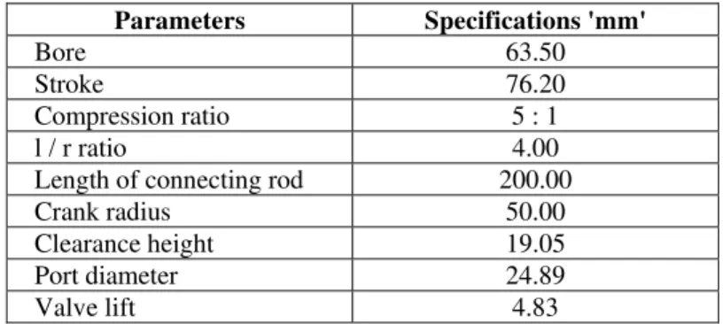
Table - 1: Specifications of the Spark Ignition Engine for (Simulated results):
Parameters Specifications 'mm'
Bore 63.50
Stroke 76.20
Compression ratio 5 : 1
l / r ratio 4.00
Length of connecting rod 200.00
Crank radius 50.00
Clearance height 19.05
Port diameter 24.89
Valve lift 4.83
Table – 2: Specifications of the Engine for (Experimental results):
Parameters Specifications 'mm'
Bore 90
Stroke 74
Compression ratio 5 : 1-19:1
Capacity 470 cc
ENGINE GEOMETRY
MODEL FORMULATION
The aerodynamic effects due to swirl and non-uniform combustion of unburned gas ahead of the flame front are neglected. The variable height ‘h’ is given by the relation,
h = ho + 1/2. S. (1 - Cos) -- (1)
Under these conditions the flame front area is given by the geometry of the flame as shown in the figure (1). Af = 2 . R F .0hd z -- (2)
The volume enclosed by flame front is given by
Vf =0h (r2+R2- R S . R . S i n) d z -- (3)
Where from the geometry,
C o s= ( R S2+ r2- R2) / 2 . R S . r -- (4) C o s= ( R S2+ R2- r2) / 2 . R S . R -- (5) r2 = R F2- z2 -- (6)
The above equations are solved by improved Euler’s method.
Normalized flame front area is given by
af = Af/ 2R2 -- (7)
Normalized volume enclosed by flame front is given by
vf = Vf /R2h -- (8)
The equation for v f can be approximated as
vf = ( 1 - y- 1) / ( 1 - y1- 1) -- (9)
Where
y = ( V / Vi) ( P / Pi) 1 / -- (10)
Where y1 is the value of y for x = 1 i.e. for fully burned mixture is given by
Where,
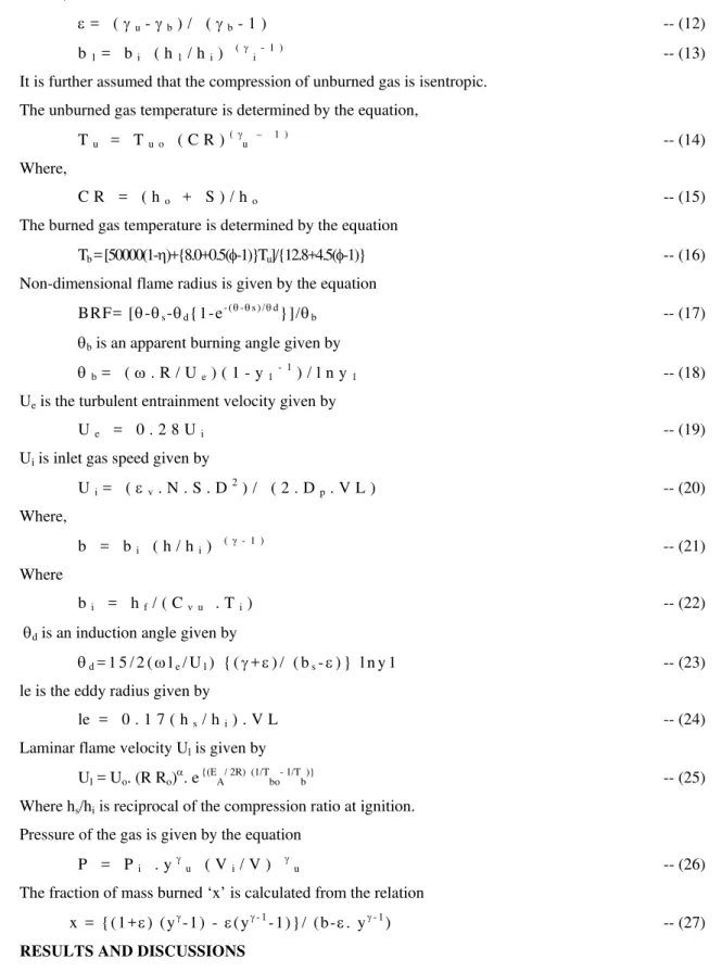
= (u-b) / (b- 1 ) -- (12)
b1= bi ( h1/ hi) (i- 1 ) -- (13)
It is further assumed that the compression of unburned gas is isentropic.
The unburned gas temperature is determined by the equation,
Tu = Tu o ( C R )(u – 1 ) -- (14)
Where,
C R = ( ho + S ) / ho -- (15)
The burned gas temperature is determined by the equation
Tb = [50000(1-)+{8.0+0.5(-1)}Tu]/{12.8+4.5(-1)} -- (16)
Non-dimensional flame radius is given by the equation
BRF= [-s-d{1-e- (-s ) /d}]/b -- (17)
b is an apparent burning angle given by
b= (. R / Ue) ( 1 - y1- 1) / l n y1 -- (18)
Ue is the turbulent entrainment velocity given by
Ue = 0 . 2 8 Ui -- (19)
Ui is inlet gas speed given by
Ui= (v. N . S . D2) / ( 2 . Dp. V L ) -- (20)
Where,
b = bi ( h / hi) (- 1 ) -- (21)
Where
bi = hf/ ( Cv u . Ti) -- (22)
d is an induction angle given by
d= 1 5 / 2 (le/ Ul) { (+) / ( bs-) } l n y 1 -- (23)
le is the eddy radius given by
le = 0 . 1 7 ( hs/ hi) . V L -- (24)
Laminar flame velocity Ul is given by
Ul = Uo. (R Ro). e {(EA/ 2R) (1/Tbo- 1/Tb)} -- (25)
Where hs/hi is reciprocal of the compression ratio at ignition.
Pressure of the gas is given by the equation
P = Pi . y
u ( Vi/ V )
u -- (26)
The fraction of mass burned ‘x’ is calculated from the relation
x = { ( 1 +) ( y- 1 ) - ( y- 1- 1 ) } / ( b -. y- 1) -- (27)
RESULTS AND DISCUSSIONS
A parametric study of combustion in spark ignition engine has been carried out with the help of the graphs generated by taking into account the effect of different engine operating parameters as well as eccentricity in spark plug.
flame zone. The spark plug location in the centre gives approximately twice the flame surface area of the side plug geometry at a given flame radius and burns about twice as fast. The maximum cylinder pressure is high at smaller values of clearance height because of higher values of compression ratio.
Fig. 5 shows the variation of normalized maximum flame front area with respect to eccentricity of spark plug for different values of clearance height at the same angle of spark. It is evident from the figure that the normalized maximum flame front area decreases with an increase in eccentricity of spark plug. It may be due to the reason that the quenching of the flame takes place with cylinder walls. The value of normalized maximum flame front area is more at higher values of clearance height because of lower compression ratios.
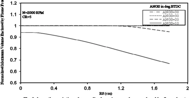
Fig. 8 shows the variation of normalized maximum volume of the flame with respect to eccentricity in spark plug for different values of spark angle at constant engine speed of 2000 RPM. The figure shows that the value of the normalized maximum volume of the flame becomes almost constant for higher angles of spark i.e. 38 and 30 deg. BTDC. But the value of the normalized maximum volume of the flame decreases slightly at higher values of eccentricity of spark plug for smaller angle of spark i.e. 20 deg. BTDC, whereas the normalized maximum volume of the flame decreases appreciably with increase in the eccentricity of spark plug at spark angle of 10 deg. BTDC.
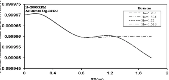
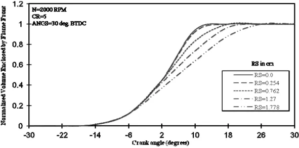
Fig. 10 shows the variation of normalized volume enclosed by flame front with respect to crank angle at different values of eccentricity in spark plug at the same angle of spark and engine speed. It can be observed from the figure that the normalized volume enclosed by flame front increases with an increase in crank angle and after a certain period it shows a constant trend for all. It can also be noticed from the figure that for higher values of eccentricities, the normalized volume enclosed by the flame front for different values of eccentricity approximately follow the similar trend.
Crank angle (Degrees)
-200 -150 -100 -50 0 50 100 150 200
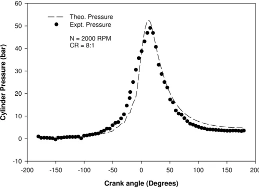
Cy li n der Pr ess ur e ( b ar ) -10 0 10 20 30 40 50 60 Theo. Pressure Expt. Pressure
N = 2000 RPM CR = 8:1
Fig. 12 shows the comparison between experimental and theoretical pressure crank angle diagram
CONCLUSIONS
The following conclusions can be drawn for the cylindrical combustion chamber in which flame propagation occurs roughly spherically:
1. By increasing the percentage in eccentricity in spark plug, the temperatures of unburned and burned gas, maximum cylinder pressure, flame front area and flame front volume will decrease.
2. A validation has been made for normalized flame front volume for reference [3]. The comparison shows good agreement between the two results.
3. A pressure crank angle diagram is also generated and validated with the simulated results. The simulated results still need to be experimentally validated for different values of eccentricities, so that it can be used as a tool for engine design.
NOMENCLATURE
D Diameter of cylindrical vessel h Variable height of the vessel ho Clearance height
S Stroke length
R Radius of cylinder RS Eccentricity of spark plug
Crank angle relative to TDC
TDC Top dead center
ANGS Angle of spark BTDC Before top dead centre Ti Temperature at end of
compression
Pi Pressure at end of compression
Vi Initial volume of mixture
Cvu Constant Volume Specific heat of
unburned gases
CR Compression ratio
CRS Compression ratio at spark
Tuo Temperature of unburned gas
before compression
Equivalence ratio (fuel-air) Tb Temperature of burned gas
Ul Laminar burning velocity
le Eddy radius
VL Valve lift
Tu Temperature of unburned gas
BRF= RF/R Non dimensional Flame radius Ue Entrainment velocity
Ui Inlet gas speed
RF Flame front radius Af Flame front area
Vf Volume enclosed by flame front
BH Normalized height i.e. h/R
, Arc angles made by flame front RPM Revolution per minute
Mole fraction of burned gas recycled
s Spark angle
v Volumetric efficiency
N Engine speed
Angular velocity L Turbulent integral scale
u Density of unburned gas
mb Mass burned
Sl Laminar flame speed
St Turbulent flame speed
Normalized chemical reaction time
RRo Density ratio
EA Apparent activation energy
Dp Port diameter
b Apparent burning angle
d Induction angle
i Inlet conditions
b Non-dimensional quantity y Non-dimensional quantity TDC Top dead centre
af Normalized flame front Area Dp Port diameter
vf Normalized volume enclosed by VL Valve lift
flame front l Connecting rod length
r Crank radius
REFERENCES
[1] Benson, R. S., Annand, W. J. D. and Baruah, P. C., "A Simulation Model including Inlet and Exhaust System for a Single Cylinder Four Stroke Cycle Spark Ignition Engine, Int. J. Mwch. Sci., 17, pp 97-126, 1975.
[2] Watson, N and Marzouk, M., "A Non-linear Digital Simulation of Turbocharged Diesel Engine under Transient Conditions", SAE 770123, 1977.
[3] Blizard, N.C and Keck, J.C., “Experimental and Theoretical investigation of Turbulent Burning Model for Internal Combustion Engines”, SAE Paper No. 740191, 1974.
[4] Bazari, Z., "A DI Diesel Combustion and Emission Predictive Capability for use in Cycle Simulation, SAE 920462, 1992.
[5] Kong, S. C. Marriot, C.D and Reitz, R. D., "Modeling and Experience of HCCI Engine Combustion using Detailed Chemical Kinetics with Multi Dimensional CFD", SAE 2001-01-1026, 2001.
[6] Zhang, D., Frankel, S.H., "Optimization of Natural Gas Engine Performance by Multi-dimensional Model", SAE 971567, 1997. [7] Fiveland, S. B. and Assanis, D. N., "Development of a Two-zone HCCI Combustion Model Accounting for Boundary Layer Effects",
SAE 2001-01-1028, 2001.
[8] Chin, Y. W., Mattews, R. D., Nicholas, S. P and Kiehne, T. M., "Use of Fractal Geometry to Model Turbulent Combustion in a SI Engine", Combustion Science and Technology, 86, pp 1-30, 1992.
[9] Annand, W. J. D., “Geometry of spherical Flame Propagation in a disc-shaped combustion chamber”, Journal of Mechanical Engineering Science. Research notes, Vol.12, No.2, 1970.
[10] Baruah, P.C., Ph.D. Thesis, University of Manchester Institute of Science and Technology (UMIST), 1973.
[11] Mc. Cuiston Jr. F. D., Lavoie G. A., and Kauffman C. W., “Validation of a Turbulent Flame Propagation Model for a Spark Ignition Engine”, SAE Paper No. 770045. pp: 200 - 223, 1978.
[12] Blumberg, P.N., Lavoie, G. A. and Tabaczynsski, R.J., “Phenomenological models for Reciprocating Internal Combustion Engines”, Prog. in Energy and Comb. Sci., 23, 1979.
[13] Tabaczynski, Rodney J., Colin R, Ferguson and Krishna Radha Krishnan, "A Turbulent Entrainment Model for Spark Ignition Engine Combustion", SAE Paper No. 770647, 1977.
[14] Groff, E. G. and Matekunas, F. A., “The nature of turbulent flame propagation in a homogeneous spark ignited engines”, SAE Paper No. 800123, 1980.
[15] Subba Rao, K, Ganesan, V, Gopalakrishnan, K. V and Murthy, B. S “Modelling of combustion process in spark ignited hydrogen engine”, Int. J. Hydrogen Energy, Vol. 8, No. 11/12, 1983.
[16] Abu- Orf G. M. and Cant R. S., "A Turbulent Reaction Rate Model for Premixed Turbulent Combustion in Spark Ignition Engines", Combustion and Flames, pp 233 – 252, August 2000.
[17] Brown N. J and Fristorm R. M.,"A Two Zone Model of Flame Propagation applied to H2 + air Flames and HCL Inhibited Flames",
published in Fire and Materials Volume 2, Issue 3 pp 117 – 121, September 2004.