Abstract—This paper presents the design, construction and
experimental evaluation of a demonstrator thermoacoustic refrigerator driven by a combustion-powered thermoacoustic engine. The system was developed to be a low-cost device for users based in remote and rural areas of developing countries. It employs a thermoacoustic engine/refrigerator coupling based on a travelling wave looped-tube configuration because of its relatively good thermal performance and construction simplicity. In the present demonstrator, a propane gas burner is used to simulate the thermal input from biomass combustion which is envisaged to be the source of energy for driving the system. Atmospheric air is applied as working fluid, while the operating frequency of the loop is 58.6 Hz. The location of the refrigerator is optimized experimentally to achieve the maximum cooling performance. So far, the lowest temperature achieved at the cold end of the regenerator is -3.6°C, while the maximum COPR achieved is 1.42%.
Index Terms—Thermoacoustic refrigerator driven by
thermoacoustic engine, travelling-wave looped-tube system, biomass combustion, rural and remote areas
I. INTRODUCTION
hermoacoustic technologies rely on a “thermoacoustic effect” understood as conversion between thermal and acoustic energies achieved by periodic compression and expansion of gas parcels in the vicinity of a solid boundary. This often takes the form of a porous structure/medium commonly referred to as a “stack” or “regenerator” placed between two heat sources. Thermoacoustic devices can be classified into “engines” or “refrigerators” depending on the practical implementation of the thermoacoustic effect. The thermoacoustic engine converts thermal energy, supplied in the form of an appreciable temperature gradient imposed on
Manuscript received March 06, 2013; revised April 20, 2013. This work was supported by EPSRC (UK) under Grants EP/E044379/1 and EP/E044379/2. Dr Kang would like to gratefully acknowledge the support from China Scholarship Council during her stay at the University of Leicester.
Patcharin Saechan is a PhD student at Department of Engineering, University of Leicester, University Road, Leicester LE1 7RH, UK
Huifang Kang is with School of Mechanical and Vehicular Engineering, Beijing Institute of Technology, Beijing, 100081, China
Xiaoan Mao is with Department of Engineering, University of Leicester, University Road, Leicester LE1 7RH, UK
Artur J. Jaworski, the corresponding author, is with Department of Engineering, University of Leicester, University Road, Leicester LE1 7RH, UK (phone: +44 (0) 116 223 1033; fax:+44 (0) 116 252 2525; e-mail: [email protected]).
the solid material, into an acoustic energy. On the other hand, the thermoacoustic refrigerator employs an acoustic wave imposed along the solid material to generate the temperature gradient [1], and thus a heat pumping/cooling effect. Thermoacoustic technologies are very attractive because of the lack of moving parts, simple low-cost construction, low maintenance cost and environmental friendliness. Furthermore, they have a potential to utilize low-quality heat sources such as industrial waste heat, solar energy or flue gases from combustion processes for energy recovery [2], [3].
The past two decades have seen a rapid development of thermoacoustic engine and refrigerator prototypes in several institutes around the world [4]-[6]. One of the most significant current challenges in thermoacoustics is to improve the energy conversion efficiency so that the thermoacoustic devices can be utilized in practical situations. A travelling-wave thermoacoustic engine leads to a relatively high thermal efficiency because it creates the travelling wave phasing to operate a Stirling-like thermodynamic cycle with high acoustic impedance in the regenerator. Currently, the maximum thermal-to-acoustic efficiency of the travelling-wave thermoacoustic engine has been measured as 32%, corresponding to 49% of Carnot efficiency [7]. In addition, travelling-wave thermoacoustic refrigerators can potentially be applied in a wide range of cooling temperatures, from room temperature down to cryogenic applications. The research work on the room-temperature thermoacoustic refrigerators aims to improve the cooling performance because devices of this type may potentially replace the traditional refrigerators. Restrictions on the use of hazardous refrigerants, such as chlorofluorocarbon (CFC), give thermoacoustic refrigerators a considerable advantage over the traditional ones since inert gases or simply air are used as working fluids. These do not cause ozone layer depletion and global-warming problems. In contrast, the related research work on the cryogenic-temperature thermoacoustic coolers has focused on the lowest achievable temperatures for particular applications including natural gas liquefiers or sensor cooling [8], [9]. The combination of a thermoacoustic engine and refrigerator leads to another type of thermoacoustic device referred to as thermoacoustic refrigerator driven by a thermoacoustic engine. The research to date on the “coupled” configuration has tended to focus on either achieving as high as possible cooling performance [10] or as low as possible cooling temperature [11] without cost
Thermoacoustic Refrigerator Driven by a
Combustion-Powered Thermoacoustic Engine –
Demonstrator of Device for Rural Areas of
Developing Countries
Patcharin Saechan, Huifang Kang, Xiaoan Mao and Artur J. Jaworski
being a particular concern. In contrast, low cost is one of the design targets in the current study.
This research is a part of the EPSRC-funded SCORE project (Stove for COoking, Refrigeration and Electricity supply). SCORE has been established in 2007 to develop the high-efficiency biomass-powered thermoacoustic system that can be a cooker, a refrigerator and an electricity generator in a single unit. The SCORE devices have been developed to meet the energy needs of remote and rural communities of developing countries that are often lacking the connection to electricity grid. Therefore, one of the main interests is the price per unit and the technological simplicity. However, the prototyping activities have been carried out in two separate streams before integrating into a single device. One involves a combustion-powered thermoacoustic electricity generator, and the other a thermoacoustic refrigerator driven by a combustion-powered thermoacoustic engine. It is hoped that the two functionalities could be merged into one design as the project culmination. The experimental results from the first stream of the project can be found elsewhere, for example reference [12]. The prototype generator is the looped-type thermoacoustic engine driving a commercial audio loudspeaker utilized as a linear alternator. Around 8 W of electricity have been extracted from this configuration. However the research on the SCORE electricity generator is still continuing in order to produce more electrical power as described in a sister-paper also in WCE2013.
The second stream of activities focused on providing a refrigeration capability and this is the scope of the current paper. The aim of this study is to show the feasibility of developing a simple and inexpensive thermoacoustic refrigerator driven by a combustion-powered thermoacoustic engine, which would allow storing vital medicines in the rural communities (e.g. vaccines). This paper presents the design, construction and testing of the prototype that is capable of producing a few watts of cooling load.
II. CONCEPTUAL DESIGN
Because of the requirements of a simple construction the important design issues include for example the selection of engineering materials, mean pressure, working fluid, and the type of thermoacoustic device. It is well known that thermoacoustic devices operating at high pressures (e.g. 30-60 bar) produce higher powers at higher efficiencies. However, engineering pressure vessels usually leads to high costs and relatively complicated designs. Therefore from the cost and simplicity point of view it is far more convenient to engineer a device working at atmospheric pressure. Here, a considerable advantage is the possibility of using widely available PVC piping for many parts of the system.
Air is used as working fluid in the proposed system since its low speed of sound leads to a compact size for a given frequency. Moreover, inert or noble gases (e.g. helium) are unavailable in remote rural communities hence refilling the system would problematic.
The design strategy of the demonstrator includes several aspects. Firstly, the system is expected to deliver good thermodynamic performance, which implies the use of a travelling-wave configuration. Secondly, it needs to be relatively simple to build, which excludes the well-known TASHE-type configuration [5], with its torus travelling-wave
resonator coupled to a standing-wave resonator controlling the operating frequency. As a compromise, a one-wavelength looped-tube design is chosen. This has the simplicity of a standing-wave build while keeping many travelling-wave device characteristics, including low power transmission losses in the feedback pipe and high power production in the engine. Additionally, the refrigerator can be located in the same loop. It is a relatively straightforward arrangement which can be applied as a practical solution.
However, an additional complication in a “coupled” engine/refrigerator system is that the installation of the refrigerator alters the favourable acoustic field distribution inside the loop. Therefore, it is crucial to minimise the changes in the acoustic field by introducing an extra phase tuning component (a matching stub) in the system. The function of the matching stub is to improve the impedance matching between the engine and the refrigerator. It is to shunt part of the volumetric velocity away from the resonator to compensate the impedance increase caused by the existence of the refrigerator inside the loop.
The design of the system discussed here is based on linear thermoacoustic theory using DeltaEC [13], a specialized computer code widely in thermoacoustics. The experimental apparatus, numerical simulations and measurement results are described in the relevant sections.
III. EXPERIMENTAL APPARATUS
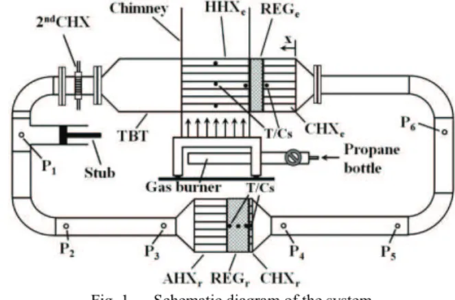
As shown in the schematic diagram in Fig. 1, the system includes two subsystems: the engine and the refrigerator, located in the same loop of a travelling wave device. The engine is powered by flue gases from propane combustion. It comprises of cold heat exchanger (CHXe), stacked screen regenerator (REGe), hot heat exchanger (HHXe), thermal buffer tube (TBT) and secondary cold heat exchanger (2ndCHX). The refrigerator is located opposite to the engine and consists of an ambient heat exchanger (AHXr), stacked screen regenerator (REGr) and cold heat exchanger (CHXr). In addition, the side branch matching stub is used while the feedback pipes complete the loop. The photograph of the rig is shown in Fig. 2. The total loop length is around 4.969 m while the operating frequency is 58.6 Hz. Subscripts “e” and “r” refer to the engine and refrigerator, respectively.
Fig. 1. Schematic diagram of the system
A. Thermoacoustic engine
The CHXe is made from a round aluminium block. Gas passages are made in the form of 45 holes with the diameter of 5 mm, drilled parallel to its centreline. 12 holes with the diameter of 6 mm are drilled perpendicular to CHXe axis to pass cooling water. This form of design has been chosen to aid the simplicity of manufacturing in developing countries. The regenerator (REGe) is made out of stainless screen disks with the mesh number of 34 and the wire diameter of 0.16 mm. 79 disks have been piled up in a stainless steel can which has a wall thickness of 2 mm. Two Type-K thermocouples (TC-Direct model 408-119) are installed at the two ends of the regenerator to monitor the temperature difference between the regenerator ends (cf. Fig. 1).
Fig. 2. Photograph of the system
The HHXe has a shell-and-tube configuration. It has 37 stainless steel tubes with I/D of 8 mm and O/D of 10 mm. The centre-to-centre distance between tubes is 15 mm; the tubes being distributed on a triangular mesh. The HHXe is heated by a propane gas burner with an adjustable heat input between 0 and 5 kW. Natural convection allows the hot flue gases to flow around the outer surface of the tube bundle, while the working gas oscillates inside these tubes as part of the thermoacoustic system. Three Type-K thermocouples are placed in three tubes to monitor the solid temperature of the tube wall (cf. Fig. 1). The HHXe configuration has been chosen as a compromise between the predicted performance from the simulation and ease of manufacture.
After the HHXe, there are TBTs, which are simply sections of stainless steel pipe. There are two different diameters of TBTs connected via a short transition cone. The 2ndCHX is introduced to remove the heat from hot air at the end of TBT. A matrix of car radiator is cut into a round disk shape and tightly fitted inside the 2-inch stainless tube, while the outside of this part of the tube is cooled by a water jacket. Heat can be removed from the hot air and transferred to the cooling water through conduction.
A “stub” tube is located at approximately 555 mm away from the secondary cold heat exchanger. It is connected to the loop through a T-junction to improve the impedance matching between the engine and the refrigerator. The stub length is much less than a quarter of the wavelength.
The next component is the feedback tube. Because the engine is designed to operate with air at atmospheric pressure, the maximum pressure difference between the inside and the outside of the resonator corresponds to the acoustic pressure, which is usually less than 0.1 bar. Therefore, the feedback pipe is made of standard 2-inch PVC
pipe and 90° bends (Class E, OD: 60.3 mm, thickness 4.5 mm) instead of a metal pipe to reduce cost.
B. Thermoacoustic refrigerator
The details of the part dimensions of the refrigerator are listed in Table II. The AHXr is made out of an aluminium block. Gas passages are made in the form of 430 holes with the diameter of 3 mm, drilled parallel to the AHXr centreline. 20 holes with the diameter of 6 mm are drilled perpendicular to the AHXr to pass cooling water.
The REGr is a stack of 60 disks of stainless steel mesh screens with mesh number 34 and the wire diameter 0.254 mm. Three Type-K thermocouples are mounted at the two ends and in the middle of the regenerator to observe the temperature distribution along the regenerator (cf. Fig. 1.).
The Ni-Cr resistance wire is situated at the cold side of the regenerator to act as a cooling load. The electrical power is supplied to the heater wires by a DC power supply. One Type-K thermocouple (TC-Direct model 408-119) is fixed at the position of the heating wire to monitor the changes of temperature as the cooling load changes.
There are six pressure transducers (PCB PIEZOTRONICS model 122A22) placed around the loop (marked P1 to P6 in Fig. 1) to measure the pressure amplitude, phase angle and frequency. All of the pressure transducers have a resolution of 7 Pa.
IV. SIMULATION
In order to perform a more detailed analysis, a specialized design tool, DeltaEC (Design Environment for Low amplitude Thermo-Acoustic Energy Conversion) and developed by Los Alamos National Laboratory is employed [13]. Its calculation capabilities and precision in modelling thermoacoustic devices have been widely validated [5], [16]. DeltaEC solves the one-dimensional wave equation based on the usual low-amplitude acoustic approximation. A solution
TABLEI DETAILS OF THE ENGINE
Parts name Dimension Other details
CHX 110 mm ID, Length 90 mm, Porosity 9.3%
Aluminium block
REG 110 mm ID, Length 23 mm, Porosity 82%, Hydraulic radius (rh) 196 µm
Stainless steel mesh screen
HHX Length 160 mm, Porosity 19.6%
Shell-and-tube configuration TBT-I 110 mm ID, Length 178 mm,
Wall thickness 2 mm
Stainless steel pipe Transitional
cone
110 mm ID1 and 54 mm ID2, Length 54 mm
Stainless steel cone TBT-II 54 mm ID, Length 160 mm,
Wall thickness 2.77 mm
standard stainless steel 2-inch pipe 2nd CHX 54 mm ID, Length 25 mm
TABLEII
DETAILS OF THE REFRIGERATOR
Parts name Dimension Other details
AHX 110 mm ID, Length 60 mm, Porosity 32%
Aluminium block
REG 110 mm ID, Length 30 mm, Porosity 73.31%, Hydraulic radius (rh) 174.4 µm
Stainless steel mesh screen
to the appropriate one-dimensional wave equation is found for each segment, with pressures and volume flow rates matched at the junctions between segments. In stacks, the wave equation solution is found simultaneously with that of the energy-flow equation in order to find the temperature profile as well as the acoustic pressure. The energy flow through stacks is determined by temperatures and/or heat flows at adjacent heat exchangers.
In the current work, DeltaEC is used to simulate the acoustic field and the acoustic power flow in the thermoacoustic device under study. The x coordinate is defined as explained in section III-A, while the model segments are mainly those shown in Fig. 1. The T-junction located after the TBT is at x = 1.21 m. The cooler location is variable (as it is in the experiments described in section VI). The engine loop is closed by a segment called “Feedback Tube” which joins the beginning of the loop (i.e. x = 0 m is equivalent to x = 4.969 m). The simulation for the thermoacoustic device is from the origin along the established coordinate through each segment, with pressures and volumetric velocities matched at the junctions between segments.
The simulation results discussed in this section are based on the optimal configuration of the prototype, i.e. where the position of the cooler is x = 2.6 m. The calculation was carried out under the following conditions: working gas is air, mean pressure is 1 bar, temperature difference between two ends of engine regenerator is maintained at 285 K and the cooling load is 0 W. The calculation results of the distributions of the acoustic field and power flow in the system are shown in Fig. 3.
Figure 3a shows the pressure amplitude distribution along the system. There are two maxima and two minima of pressure amplitude along the loop. Both regenerators are located near the maxima of pressure amplitude. As shown in Fig.3a, the disagreement between measured (red dots) and calculated pressures is typically around 4%, and at most 6%. The agreement between the measured and calculated values was needed to yield confidence in the numerical predictions. It forms the basis for a better understanding of the velocity, leading phase and power flow in the device.
Figure 3b shows the distribution of volumetric velocity along the system. There are also two maxima and two minima along the loop. The regenerator of the cooler is located near the minimum of volumetric velocity amplitude. The small volumetric velocity within the regenerator is preferred to avoid high viscous dissipation, which is one of the design strategies behind the current concept. However, the velocity at the regenerator of the engine is relatively large, which will cause a low efficiency. Of course this is not an ideal condition for a travelling wave engine to operate, and will be improved in future. It can also be seen that the volumetric velocity increases significantly along the regenerator of engine. This is due to the sharp temperature gradient along the regenerator. Furthermore, at the location of the stub, there is a sudden increase of the volumetric velocity. Along all other parts, the volumetric velocity changes smoothly.
Figure 3c shows the acoustic impedance along the system. It can be seen that the acoustic impedance is highest at the cold end of the cooler regenerator. The stub introduces a local decrease of the acoustic impedance along the loop. Figure 3d shows the phase difference between pressure and velocity
oscillation along the system. It can be found that the engine regenerator works in the region of -54.7º < φ < -61.7º. Of course this is not an ideal condition for a travelling wave engine to operate. However it needs to be remembered that the system has been optimised for a coupling with the alternator in the configuration for electricity generation. Introduction of a cooler instead of alternator will lead to a substantial change in the acoustic field and further modifications to the acoustic network will be needed to counteract such changes. The non-ideal engine conditions will of course adversely affect the cooler performance.
Fig. 3. Numerical predictions of the acoustic field and power flow in the system: (a) pressure amplitude; (b) volumetric velocity; (c) acoustic impedance; (d) phase angle; and (e) acoustic power flow. Red symbols
indicate measured pressure amplitudes.
Figure 3e shows the acoustic power flow along the system. It can be found that around 7.2 W of acoustic power is fed into the CHXe which dissipates around 0.3 W. The remaining 6.9 W is fed into the cold end of REGe. Within REGe, the acoustic power is amplified to around 13.9 W which is the level of acoustic power flowing out from the hot end of REGe. These calculations show that the engine can produce a net acoustic power of about 7.0 W at an input heat power of 128 W, corresponding to a thermoacoustic conversion efficiency of 5.6%. The HHXe, TBT and 2ndCHX dissipate around 0.6 W. The acoustic power of 1.4 W enters the stub. The acoustic power of 10.6 W enters the ambient end of the REGr and is used to pump heat. It is reduced gradually due to the consumption of acoustic power for pumping heat from the cold end of REGr. When it comes out of the CHXr it has a value of 7.7 W, which means that the acoustic power consumed by the cooler is 2.9W. The cooler can realize the cooling temperature of 251.1K.
was achieved by introducing Gedeon streaming. For example, the system without Gedeon streaming can realize the pressure amplitude of 5766 Pa at a reference point and the cooling temperature of 191.4 K. When the Gedeon streaming is considered in the calculation, the pressure amplitude obviously decreases and the cooling temperature goes up to match better the measured values. Indeed, there is independent evidence from experiments that Gedeon streaming is indeed an issue. Figure 4 illustrates the measured temperature profiles along REGr for the eight studied locations of the refrigerator. Clearly these are strongly nonlinear. In the present work, Gedeon streaming has not been eliminated as it is an initial characterisation of the system and evaluation of the modelling capabilities.
Fig. 4. Temperature profiles along the refrigerator’s regenerator refrigerator
V. THE PERFORMANCE INDICATORS
The acoustic power (E&) consumed by the refrigerator to remove the cooling load at the cold heat exchanger is the difference between the acoustic power flowing into and out of the refrigerator. It can be measured by the two-microphone method [14] using readings from P2-P3 and P4-P5, respectively. The acoustic power at the mid-point between the two pressure sensors is obtained from the following equation:
(
)
(
)
(
)
⎟ ⎟ ⎠ ⎞ ⎥ ⎦ ⎤ ⎢ ⎣ ⎡ ⎟ ⎠ ⎞ ⎜ ⎝ ⎛ Δ Δ ⎟⎟ ⎠ ⎞ ⎜⎜ ⎝ ⎛ − + + − − × − + ⎪⎭ ⎪ ⎬ ⎫ ⎥ ⎦ ⎤ ⎟ ⎠ ⎞ ⎜ ⎝ ⎛ Δ Δ ⎟⎟ ⎠ ⎞ ⎜⎜ ⎝ ⎛ − + + ⎢ ⎣ ⎡ − − ⎜ ⎜ ⎝ ⎛ ⎩ ⎨ ⎧ − Δ = a x a x P P r a x a x r P P a x a A E ω ω σ γ σ γ δ ω ω σ γ σ γ δ ω ρ ν ν csc 1 1 1 1 4 cot 1 1 1 1 2 1 ~ Im / sin 2 2 2 2 1 0 0 2 1 & (1)where A is the cross sectional area of the pipe, a is the speed of sound, ρ is the mean density, ω is the angular frequency,
Δx is the distance between the two pressure transducers, P1
and P2 are the amplitudes measured by the two pressure transducers, symbol ”~” is the conjugation of a complex quantity, δν is the viscous penetration depth, r0 is the pipe
radius, γ is the specific heat ratio, and σ is the Prandtl number.
The electrical power supplied to the heater to simulate the cooling load of the refrigerator is given by:
IV
Q&load = , (2)
where I is the current and V is the voltage. The coefficient of performance (COP), which indicates the performance of the
refrigerator, is defined as the ratio of the cooling load to the net acoustic power consumed by the refrigerator:
net load E
Q
COP= & & . (3)
In order to observe the performance of the refrigerator at different operating conditions, the COPR, which is the ratio of the COP to the COP of the Carnot cycle, is applied:
COPC COP
COPR= , (4)
Where COPC is the maximal theoretical performance of the refrigerator at a given temperature difference according to the Carnot cycle:
) ( a c
c T T
T
COPC= − , (5)
where Tc is the absolute temperature of the cold heat
exchanger and Ta is the absolute temperature of the ambient
heat exchanger.
VI. EXPERIMENTAL RESULTS AND DISCUSSION For the “coupled” configuration of the engine and the refrigerator in the looped-tube, there are many parameters that affect the performance of the system such as configuration of each component, mean pressure, input power or the relative locations of engine and refrigerator, because these variables have an effect on the acoustic impedance inside the system. Here, the effect of the refrigerator position (measured along the loop from x = 0) on the cooling performance is investigated. The cooling performance is indicated by COPR and the cold end temperature. Constant flow rate of propane is applied to the burner in order to supply heat to the engine. The temperature of the hot end of the regenerator in the engine is observed to be between 338 and 357 ºC, and the temperature in the hot heat exchanger (HHX) between 484 and 516 ºC. In all experiments, the stub is adjusted to achieve the maximum acoustic power supplied to the refrigerator. However, the minimum temperature difference between two ends of the regenerator allowing the system to start is around 164 ºC for refrigerator position x = 2.60 m. The experiments are carried out in such a way that after the start-up, the system is allowed to reach a thermal equilibrium in all its components (while trying to keep the reference temperatures given above as close to constant values as possible).
Figure 5 shows the cold end temperature of REGr at no cooling load condition and the acoustic power consumption for different locations of the refrigerator. Clearly the optimum position is x = 2.60 m (highest acoustic power consumption of 10.4 W and lowest temperature of the cold end of REGr of -3.6 ºC).
Fig. 5. The acoustic power consumption and cold end temperature of the regenerator without cooling load for various locations of the refrigerator
Fig. 6. The cooling performance for various locations of the refrigerator
Fig. 7. The measured COPR at different locations of the refrigerator
Finally, the measured COPR as a function of the cooling load, for various cooler locations, is presented in Fig. 7. The value of COPR is zero at no cooling load condition due to lack of heat input to the CHXr. In refrigerator, the temperature difference across the regenerator is created because of the thermoacoustic heat pumping effect. For all positions of the refrigerator, it can be seen that COPR increases as cooling load increases and reaches a peak at a specified cooling load, then starts to decrease. The magnitude and the position of the peak change as the position changes. This reduction can be explained by the fact that the heat pumping effect on the regenerator is not sufficiently strong to remove all of the heat input; the temperature starts to build up, and eventually becomes equal to the temperature at the ambient end of regenerator. In addition, the maximum COPR shifts to higher heat loads as the acoustic power consumption increases. The achieved maximum COPR of the system is 1.42% at the cooling load of 5.9 W at the optimum location of the refrigerator.
VII. CONCLUSION AND FUTURE WORKS
A “coupled” configuration of the thermoacoustic engine and refrigerator in a looped-tube configuration, working at frequency of 58.6 Hz, was tested in this study. The whole system was tested at different locations of the refrigerator relative to the engine and at constant propane gas flow rate for the combustion. The lowest cooling temperature of -3.6 ºC can be produced for the optimum refrigerator location x = 2.60 m away from the reference point. The experimental results indicate that this system is able to produce enough cooling power for storing small quantities of vital medicines in remote and rural areas of developing countries to meet the objectives of the SCORE project. The next step of this research is to optimise the system with different parameters for obtaining the higher cooling performance. In particular the system will need to be modified to eliminate Gedeon streaming by putting a membrane in a suitable location. It will also be tested and modelled for different operating frequencies. The issue of a non-optimal phase difference in the engine regenerator will be considered and appropriate control strategies developed.
REFERENCES
[1] G.W. Swift, “Thermoacoustic engines,”J. Acoust. Soc. Am., vol. 84, no. 4, pp. 1145-1180, Oct. 1988.
[2] K. De Blok, “Low operating temperature integral thermo acoustic devices for solar cooling and waste heat recovery,” in Acoustic’08, Paris, 2008, pp. 3545-3550.
[3] Z. Wu, W. Dai, M. Man and E. Luo, “A solar-powered traveling-wave thermoacoustic electricity generator,” Solar Energy, vol. 86, no. 9, pp. 2376-2382, Sep 2012.
[4] G.W. Swift, “Analysis and performance of a large thermoacoustic engine,” J. Acoust. Soc. Am., vol. 92, no. 3, pp. 1551-1563, Sep. 1992. [5] S. Backhaus and G.W. Swift, “A thermoacoustic-Stirling heat engine: Detailed study,” J. Acoust. Soc. Am., vol. 107, no. 6, pp. 3148-3166, Jun. 2000.
[6] T.J. Hofler, “Thermoacoustic refrigeration design and performance,” Ph.D. dissertation, Dept. Physics, Univ. California, San Diego, CA, 1986.
[7] M.G.H. Tijani and S. Spoelstra, “A high performance thermoacoustic engines,” J. Appl. Phys., vol. 110, no. 9, pp. 093519, Nov. 2011. [8] E. Luo, Y. Huang, W. Dai, Y. Zhang and Z. Wu, “A high-performance
thermoacoustic refrigerator operating in room-temperature range,”
Chin. Sci. Bull, vol. 50, no. 22, pp. 2662-2664, Nov. 2005.
[9] W. Dai, G. Yu, S. Zhu and E. Luo, “300Hz thermoacoustically driven pulse tube cooler for temperature below 100K,” Appl. Phys. Lett., vol. 90, no. 2, pp. 024104, 2011.
[10] B. Yu, E.C. Luo, S.F. Li, W. Dai and Z.H. Wu, “Experimental study of a thermoacoustically-driven traveling wave thermoacoustic refrigerator,” Cryogenics, vol. 51, no. 1, pp. 49-54, Jan. 2011.
[11] W. Dai, E. Luo, J. Hu and H. Ling, “A heat-driven thermoacoustic cooler capable of reaching liquid nitrogen temperature,” Appl. Phys. Lett., vol. 86, no. 22, pp. 224103, 2005.
[12] Z. Yu and A.J. Jaworski, “Demonstrator of a combustion driven thermoacoustic electricity generator for remote and rural areas of developing countries,” in ICSV 19, Lithuania, Jul. 2012.
[13] B. Ward, J. Clark and G.W. Swift, Design Environment for Low-Amplitude ThermoAcoustic Energy Conversion (DELTAEC) program, Los Alamos National Laboratory, New Mexico, USA, 2008. [14] A.M. Fusco, W.C. Ward, and G.W. Swift, “Two-sensor power
measurements in lossy duct,” J. Acoust. Soc. Am., vol. 91, no. 4, pp. 2229–2235, Apr. 1991.
[15] NHS. (2010, July 21). Vaccine cold storage [Online]. Available:
http://www.nrls.npsa.nhs.uk/alerts/?entryid45=66111