ISSN 1549-3636
© 2010 Science Publications
Corresponding Author: Edward Sek Khin Wong, Faculty of Business and Accountancy, University of Malaya, 50603, Kuala Lumpur, Malaysia
Advanced Information Technology of Slot-Switching Network Schemes
for on All-Optical Variable-Length Packet
1
Soung Yue Liew,
2Edward Sek Khin Wong and
2Choong Kwai Fatt
1
Department of Information Technology
University Tunku Abdul Rahman, 46200, Petaling Jaya, Malaysia
2
Department of Information Systems, Faculty of Business and Accountancy,
University of Malaya, 50603, Kuala Lumpur, Malaysia
Abstract: Problem statement: The purpose of this paper was to investigate all optical packet switching, because it was the key to the success of the future Internet. It can meet the stringent bandwidth requirement of future Internet applications, such as real-time video streaming. Due to the lack of optical Random Access Memory (RAM), however, the all-optical schemes studied in the literature were either not flexible enough to accommodate Internet packets, which were variable-length in nature, or fail to schedule packets at switches to achieve low loss rate. Approach: The aim of this paper was thus to tackle the flexibility and utilization issues in all-optical packet switches, even at the absence of optical RAM. We approached this paper by first studied a new slotted model for all-optical variable-length packet switching, which was called Variable-length-Packet Fixed-Length Slot (VPFS) switching. Results: We proved by mathematical analysis the theoretical maximum utilizations that can be achieved by the model in two variant schemes. Then we proposed a new scheduling algorithm for shared-fiber-delay-line switches in order to achieve low loss rate when the utilization approaches the maximum. We justified our design by simulation. In our finding, through mathematical analysis and computer simulation, our proposed switching model and scheduling algorithm can be coupled well to achieve good performance for all-optical packet switches. We also found that the selection of the slot size in the network was very critical as it determined the transmission overhead and hence the utilization of the all-optical network. Our research limitation depended on slot size. Although a small slot size was critical for high utilization with our model, it was not always preferable. It was because a small slot size increased the switching and scheduling complexity at the switch. Thus the selection of an optimum slot size for the network was a compromise between utilization and complexity. Conclusion/Recommendations: A fast scheduling algorithm has been studied in order to reduce the scheduling complexity so as to increase the utilization without much penalty. In regard to the practical implications, the VPFS was a promising model to fully utilize the huge capacity of all-optical networks and to accommodate variable-length packets for future Internet traffic. With VPFS, the selection of the slot size was critical, and it was a compromise between the network utilization and scheduling complexity.
Key words: All-optical network, variable-length packet, slot switching, fiber delay line, scheduling algorithm
INTRODUCTION
In the past decades, research has been actively conducted to make all-optical packet switches and subsequently all-optical packet networks, a reality. A major difficulty remains-packet contention. Two primary contention-resolution methods have been intensively studied within the literature to attempt to resolve this problem. The first is the wavelength
are bulky, only a limited amount of such memory is usually recommended when building these optical switches. To efficiently make use of the FDL resource has become an important timing issue within the contention-resolution situation.
Numerous switch architectures and scheduling algorithms have been proposed for the efficient timing, switching and scheduling of optical packets in an all-optical switch that uses FDLs. Some examples are, Time-Slice Optical Burst Switching (Ramamirtham and Turner, 2003), Karol’s Algorithm (Karol, 1993), Optical Packet Switching (Chia et al., 2001; Chao and Choa, 1999; Karol, 1993; Hunter et al. 1998; Guillemot et al., 1998), Optical cell switching (Chao and Liew, 2003; Masetti et al., 1993) and the Sequential FDL Assignment (SEFA) Algorithm and its variant (Liew et al., 2005; Shi Jiang et al., 2005). These algorithms however have placed constraints upon the amount of traffic processed, from fixing the packet lengths, to requiring packets to be aligned before switching, making these switches impractical in a real-world environment where throughput is critical for their economic justification and use.
Algorithms for routing variable-length, unaligned packets are needed in order to overcome these problems. As FDLs are used to buffer optical packets, a fixed granularity of the switching or scheduling unit, that is, the slot size, needs to be imposed depending on the buffer management scheme used (Hiroaki and Masayuki, 2006; Hiroaki et al., 2006).
A Variable-length-Packet Fixed-length-Slot (VPFS) switching model is one that accommodates these variable-length packets by using the fixed-length slots within current optical switches.
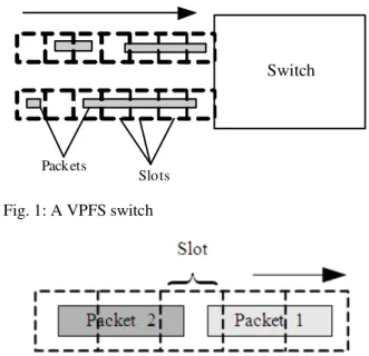
In a VPFS network, all switches adopt the same slot size but slot boundaries are not synchronized from one switch to the next. With reference to Fig. 1, when a packet of any length arrives at a VPFS switch, a slot or a chain of consecutive or contiguous slots must be assigned to carry that packet from the input and if buffering is necessary, passing through the same FDL path, to the destined output. Note, it is not possible for a chain of slots that are carrying a given data packet to be broken up and routed separately within the switch, as this is due to the physical properties of an optical data packet. Since a slot is the minimum switching or scheduling unit and cannot be further split, any slot carries data for a given packet only.
Figure 2 shows head-tail clashing. This occurs if the tail of a packet and the head of its following packet fall into the same slot within a VPFS switch that is without an aligning capability. The following packet will then be dropped and not switched to its output.
Switch
Slots Packets
Fig. 1: A VPFS switch
Fig. 2: Packet 2 will have to be dropped due to head-tail clashing
Head-tail clashing deteriorates the performance of a VPFS and solutions to this problem have not been widely studied within the available literature.
To alleviate or even eliminate this phenomenon, three solutions are possible.
The first is to select a small slot size for the VPFS network, as this reduces the chance of head-tail clashing. The advantages of a small slot size is not only limited to the reduction of the occurrence of this problem, but also, to the timing effects of minimizing processing overheads while maximizing the link utilization of VPFS. The VPFS model can be further generalized to a generic variable-length packet switching as the selected slot size is allowed to approach zero, again a situation where no head-tail clashing occurs, but little switch processing as well. The apparent and real challenge of switching and scheduling is in the selection of the size of the slot in a VPFS.
The second solution is to force all sources and switches in a VPFS network to impose a gap between any two packets departing from the same output link, so that when the packets arrive at the next switch, there will be no head-tail clashing. In this case, the size of the gap must be at least the slot size. This approach is termed ‘constrained VPFS scheme without alignment.’ Although this scheme can eliminate head-tail clashing, the price to be paid is large overheads and low link utilization, or switch throughput.
boundary. As long as the network traffic satisfies a given and certain condition, we show that the VPFS scheme with alignment can eliminate the head-tail clashing problem throughout the network with minimum overheads. Here, it is regarded as a best-case benchmark for other VPFS schemes. There is a price to be paid for this approach; the optical signals may need to be switched a number of times within the aligners before they enter the switch fabric (Chao et al., 2000) and this can result in unacceptable levels of signal attenuation.
As we study the performances of (i) generic VPFS without alignment, (ii) constrained VPFS without alignment and (iii) VPFS with alignment, we propose a variable-length Packet FDL Assignment (VAPFA) algorithm for shared-FDL all-optical packet switches.
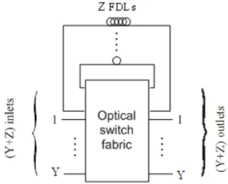
With reference to Fig. 3, a shared-FDL all-optical switch contains a number of feedback FDLs that are shared among all input ports and each FDL can delay packets by a fixed number of slot times. Slot time is a concept in computer networking. It is twice the time it takes for an electronic pulse (OSI Layer 1-Physical) to travel the length of the maximum theoretical distance between two nodes.
Assume that there are Z feedback FDLs, Y input ports and Y output ports. The outputs (inputs) of FDLs and the inputs (outputs) of the switch are collectively called the inlets (outlets) of the switch fabric, yielding Y+Z inlets and Y+Z outlets.
The shared-FDL optical switch has been studied extensively in the literature (Hiroaki et al., 2006; Karol, 1993; Shi, 2005) and in (Hiroaki et al., 2006) it has been proposed to handle variable-length packets. However, the algorithm proposed in (Hiroaki et al., 2006) is a non-reservation algorithm which does not provide departure scheduling and it cannot guarantee the packets being buffered are able to access the desired output ports after coming out of the FDLs. Since the departure time is not scheduled in advance, the delay bound of the algorithm is undefined and it may require a packet to be switched and re-circulated many times.
Fig. 3: A single-stage shared-FDL optical switch
In this study, we focus on the reservation scheduling algorithms for variable-length packets in the single-stage shared-FDL switch, which is known as the VAPFA algorithm. The VAPFA algorithm is extended from the SEFA algorithm proposed in (Liew et al., 2005). In contrast to the non-reservation scheduling algorithms, the VAPFA algorithm performs the FDL assignment for the entire journey of a delayed packet so that it can be scheduled to match with the desired output port in a future time. As optical packets cannot be fragmented, it should be noted that in a valid FDL assignment, all slots that belong to the same packet must always pass though the same FDL path from the input to the output. If a packet that needs to be delayed fails to be assigned a FDL path to some future time for the desired output port owing to FDL and/or output-port conflicts, it is discarded without entering the switch so that it does not occupy any resources.
Firstly, we analyze the arrival overhead and maximum link utilization of the generic VPFS without alignment. Under methodology, we discuss the VAPFA scheduling algorithm for shared-FDL switches. Then, we provide the simulation model and results for the generic VPFS. Under discussion, we propose, analyze and evaluate the constrained VPFS without alignment, which is designed for eliminating the head-tail clashing throughout the VPFS network. As a best-case benchmark, the VPFS with alignment scheme is also being studied under conclusion.
MATERIALS AND METHODS
Generic VPFS without alignment: Here we consider a generic VPFS without alignment and part of the content shown in the following appears in (Liew et al., 2007).
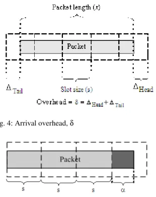
Consider a packet with length x arriving at a VPFS switch, where a fixed slot size of s is adopted. Let m denote the number of consecutive slots required to carry the packet, where m can either be x/s or x/s+1. For example, if s = 1 and x = 3.5, the value of m can either be 4 or 5, depending on the arrival time of the packet. The arrival overhead of the packet is defined as δ = ms-x, which consists of the head overhead (∆Head) and tail overhead (∆Tail), as shown in Fig. 4. The value of δ can either be x/s⋅ s-x or x/s⋅ s+s-x.
Fig. 4: Arrival overhead, δ
Fig. 5: α, the data size that may cause overhead
Lemma 1: For any packet, the expected arrival overhead at a VPFS switch without alignment is equal to slot size s.
Proof: With reference to Fig. 5, let α = x+s- x/s⋅ sbe the non-zerodata size from the packet that may cause arrival overhead, where 0<α≤ s. By the definition of α, the arrival overhead can either be (s-α) or (2s-α), with probabilities:
Prob{δ = s-α}= (s-α)/s
Prob{δ = 2s-α} = α/s
The expected arrival overhead can then be given by:
2 2 2
2
s (s 2s ) 2s
E[ ] (s ) (2s )
s s s
s s s
− α α − α + α + α − α
δ = − α × + − α × =
= =
QED
As a result of Lemma 1, a smaller slot size reduces wastage of bandwidth. More importantly, it increases the bound of the effective utilization of VPFS. Let U denote the effective link utilization, where dropped packets due to head-tail clashing are discounted. The
upper bound of U in the VPFS without alignment scheme is derived as follows.
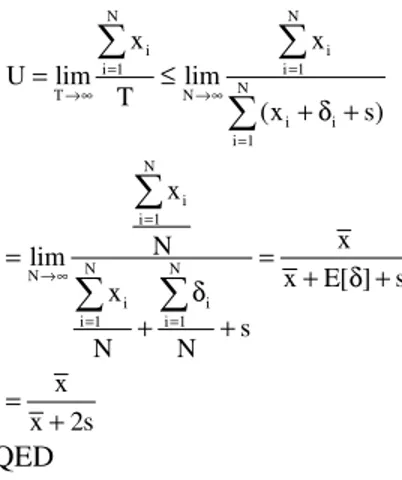
Theorem 1: Given that the length of a packet is a random number, x, with an average value of x, the effective link utilization of the VPFS switching scheme without alignment is bounded by x
x+s.
Proof: Consider observing a VPFS switch over duration of T, in which N valid packets have arrived and been considered for switching. Let xi be the length and δi the arrival overhead of the ith packet, where 1≤i≤ N. Note that:
N
i i
i 1
T (x )
=
≥
∑
+ δWe have:
N
N N i
i 1
i i
i 1 i 1
N N N
T N N
i i i i
i 1 i 1 i 1
x
x x
x N
U lim lim lim
T x E[ ]
(x ) x
N N
x x s
=
= =
→∞ →∞ →∞
= = =
= ≤ = =
+ δ
+ δ δ
+
= +
∑
∑
∑
∑
∑
∑
QED
From Theorem 1, to achieve a better utilization, again, a smaller slot size for the VPFS switching scheme is preferred. However, there are several constraints that restrict a network designer’s ability to choose a very small slot size. (1) Compared with the electronic switches, all-optical switches require longer configuration time to accommodate packets from different inputs to different outputs; therefore the slot size cannot be too small. (2) For a smaller slot size, more consecutive and contiguous slots are required to contain a data packet and all these slots must be scheduled together from the input to the output, passing through the same FDLs whenever buffering is necessary, this increases the switching and scheduling complexity of the all-optical switch.
RESULTS
(a) (b)
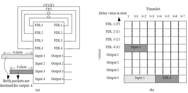
Fig. 6: Shared-FDL switch and configuration table (a) 4×4 shared FDL switch (b) configuration table
Within each VAPFA switch, a configuration table is maintained. The configuration table is used for storing the connectivity schedule of the switch fabric. An example is given in Fig. 6, where Fig. 6b shows the configuration table of the 4×4 switch given in Fig. 6a. Note that the rows of the table represent the outlets of the switch fabric and the columns the timeslots. In this example, the first 4 rows represent FDLs with delay values 1, 1, 2 and 4 slots, respectively, followed by 4 rows representing 4 output ports.
When a route is reserved for a packet, the table stores the inlet, from which the packet is coming, into the corresponding entries of the table. In this example, two packets, both destined for output port 4, are arriving at input ports 1 and 3, requiring 4 slots and 3 slots to carry, respectively. Assuming that there is no other traffic, the packet from input 1 can be immediately arranged to be transferred to output 4 from timeslot t (current timeslot) to timeslot t+3, as shown in the configuration table. However, as output 4 is no longer available from t to t+3, the second packet has no choice but to travel through FDL 4, which has a delay value of 4 timeslots and only then it can be scheduled to be transferred to output 4 from t+4 to t+6. This FDL route is reflected in the configuration table by placing input 3 to the row of FDL 4 from t to t+3 (as this packet requires 3 slots to carry) and then placing FDL 4 to the row of output 4 from t+4 to t+6.
If a packet arrives and it has no reserved route, the packet is dropped and considered lost. This route reservation is performed using the following steps:
1. Repeat for each timeslot 2. Repeat for each input port 3. If there is a new packet
4. Check configuration table for an immediate solution
5. If there is an immediate solution
6. Update output port in configuration table to reserve the route
7. If there is no immediate solution
8. Search for a possible combination of delays using FDLs that will delay the packet till future time where output port is available in a number of consecutive slots, the total duration of which is long enough to transmit the packet
9. If there are more than one solution
10. Select the best solution and update the configuration table to reserve the route.
11. If there is no solution, packet is dropped
slots to be 1/100 of a sec, then we can assume that the algorithm will loop step 1 for 100 times every sec.
In step 2, we loop through the remainder of the algorithm for every input port that is attached to the switch. This means, for every timeslot, all the input ports are looped through for processing. If there are 32 input ports, then step 2 will be repeated 32 times for every timeslot. The input ports are cycled through sequentially, from smallest to largest borrowing from the sequential nature of SEFA.
Step 3 checks if there is a signal for a new packet at that current timeslot. This is important because not every timeslot will have a new packet arriving for each respective input port, because we assume that packets are variable length and some packets may consume more than 1 slot, requiring a chain of slots. For instance, a packet arriving at time t, 3 slots long, for a particular input port would mean that corresponding input port will have no new packets arriving at least till time t+3.
If there is a new packet arriving at a particular input port at the current timeslot of the switch, we immediately check to see if there are enough vacant slots in the output port to contain the incoming packet without using any FDLs for delay (step 4). If the output port is indeed available, the configuration table of the switch is updated (step 5) to reserve the output port for the number of slots the incoming packet consumes. It is also important to note at this point that due to the physical properties of an optical data packet, it is not possible for a chain of slots that are carrying a certain packet to be broken up and routed separately. Therefore, whenever the configuration table is look-up to find if there are enough empty slots to contain the incoming packet, these vacant slots must be contiguous in order to contain the complete chain of slots for the packet.
When there is no immediate solution (step 7), we search through all the FDLs using Breadth First Search (BFS) to find a combination of delays that will delay the slot or slots long enough till there is a vacant chain of slots in the output port which is sufficient to contain the incoming packet (step 8). For this portion, we represent each FDL as a node in a search tree and the depth of the search tree represents how many FDLs (recirculation) a packet has to traverse before reaching a solution. (In graph theory, Breadth-First Search (BFS) is a graph search algorithm that begins at the root node and explores all the neighboring nodes. Then for each of those nearest nodes, it explores their unexplored neighbor nodes and so on, until it finds the goal).
Finally, if the algorithm manages to return a set of solutions (step 9) we select the solution with the lowest recirculation (least FDLs used). This is because each
recirculation will cause signal attenuation. In the event that there are a number of solutions that use the same number of circulations, we pick the solution that causes the least delay to a packet.
For example, if solution A uses two FDLs with delay values 2 and 16 timeslots and solution B uses two FDLs with delay values 4 and 4 timeslots, we choose solution B because the total delay time (4+4 = 8) is less than that of A (2+16 = 18). Assuming there exists a solution C that uses three FDLs, each with the same delay value of 2 timeslots, we still choose solution B because it uses fewer circulations, although the total delay incurred in solution C is less than that in solution B. In fact, solution C would not even be considered as in a breadth first search, once a solution is found in the search tree at depth 2, the algorithm would not proceed to search for a solution at depth 3. However, a normal breadth first search will stop when one solution is found, but we expand the algorithm to finish searching the entire child nodes that have the same depth where a solution can be found. This allows the algorithm to pick the best solution with the same depth instead of picking the first solution found, which may not be optimal.
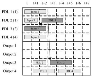
Finally, in step 10 we update the configuration if a best solution can be found. If there are no solutions, we consider the packet lost and discard it when it arrives because there are no possible routes reserved for it in the configuration table. Figure 7 shows the updating of the configuration table with the only possible solution for a packet from input port 4, with slot length 3, arriving at time t, destined for output port 3. It is delayed for 2 timeslots using FDL3, then delayed again for 1 timeslot using FDL2 and exits at time t+3 at output port 3.
FDL 1 (1)
FDL 2 (1)
FDL 3 (2)
FDL 4 (4)
Output 1
Output 2
Output 3
Output 4
t t+1 t+2 t+3 t+4 t+5 t+6 t+7
Inp ut 2 Inp ut 1
Input 3
FDL 1 FDL 4
FDL 2 Inp ut 4
FDL 3
FDL 2
The time required to assign an FDL route for a packet is proportional to m, where m is the number of slots that the packet need to load. This is because we need to access a node on the search tree m times to examine whether the FDL/output is available for m consecutive timeslots. Since m is inversely proportional to the slot size, the time complexity of the VAPFA algorithm is inversely proportional to the slot size as well. In other words, the smaller the slot size, to a certain packet, the more time it takes to assign an FDL route.
Simulation of VAPFA algorithm in generic VPFS: To focus on the switch performance when simulating a generic VAPFA switch in the generic VPFS, we assume that incoming traffic is regulated in such a way that no head-tail clashing will occur and thus no packet will be dropped due to such a phenomenon. It should be noted that such an assumption is valid at those switches immediately next to the sources because sources can choose to send packets under any traffic regulations. For other intermediate switches, however, only when the condition described in the constrained VPFS applies, the head-tail clashing can then be eliminated, assuming no packet alignment. The constrained VPFS will be discussed in the followings.
Given the value of the effective link utilization, U and the packet length probability density function (pdf), f(x), two random numbers need to be generated in order to determine (i) the arrival of a packet and (ii) the number of consecutive slots that the packet need to load.
To design the random number generator which determines the arrival of a packet, let P denote the probability that a packet is arriving in an undetermined slot.
Corollary 1: In the VPFS scheme without alignment, the probability that a packet is arriving in an undetermined slot is given by:
sU P
x(1 U) =
−
Proof: Let M be the number of empty slots and N the number of packets in the duration of T. Note that M+N is the total number of events observed in T, where:
N
i i
T
i 1
N
P lim and, T (x ) M s
N M
→∞ =
= = + δ + ×
+
∑
By the definition:
N N
i i
i 1 i 1
N T T i i i 1 N i i 1 N T T i i i 1 T x x
U lim lim
T
(x ) M s
x N
N x N
lim lim
N (x s) M s
(x )
N M s
N N x N M lim N M
(x s) s
N M N M
Px Px
P(x s) (1 P)s Px s
= = →∞ →∞ = = →∞ →∞ = →∞ = =
+ δ + ×
× × = = × + + × + δ × + × × + = × + + × + + = = + + − +
∑
∑
∑
∑
∑
Thus: sU P x(1 U) = − QEDFrom corollary 1, one can translate a given link utilization to the probability that is required in the packet arrival generator for simulation. After the arrival of a packet is generated, the next step is to generate the packet length and determine the number of loaded slots based on the given pdf f(x).
To simplify the analysis, we assume that there is a maximum size for the packets, the value of which is normalized to 1. In other words, the packet length, x, falls in the range of (0, 1]. Since 1 unit is the maximum packet length, we further assume that the slot size of the VPFS switch to be s≤1, because having slots larger than the maximum packet size would cause wastage due to overhead and void spaces. Assume that s = 1/n, where n is a positive integer. In this case,1≤ ≤ +m n 1, where m is the number of slots that a packet may occupy. A random number generator is therefore needed to generate m with respect to f(x). The probability distribution of m is thus given by: 1 n 0 y 1 n y 2 n y n y 1 n 1 n 1 n Prob{m y}
(1 nx)f (x)dx, for y 1 ;
{nx (y 2)}f (x)dx
(y nx)f (x)dx for 2 y n;
{nx (n 1)}f (x)dx , for y n 1
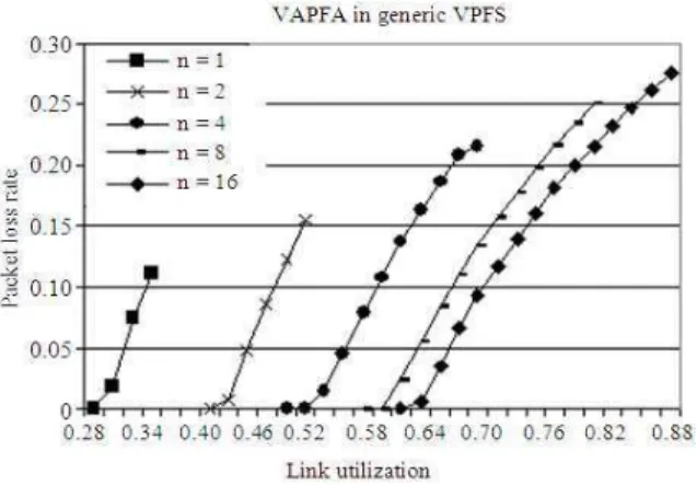
Fig. 8: Packet loss Vs Link utilization in a generic VPFS switch
For instance, if f(x) = 1 from 0-1, then Prob{m = 1} = Prob{m = n+1} = 1
2n and Prob{m = y} = 1 n for 2≤y≤n. With the distribution, one can use another random number generator to generate packet lengths for packets.
In the following, we show the simulation model and results of the VAPFA algorithm without alignment. We study a 32×32 shared-FDL switch with 32 FDLs and assume that the normalized packet length is a random number uniformly distributed from 0-1, that is, f(x) = 1 and 0<x≤1. In order to evaluate how the selection of slot size affects the performance of the switch, we further assume the slot size s = 1/n, where n is a positive integer. In this case, the largest packet in the simulation will have an equivalent length of n slots. Another factor that may affect the switch performance is the lengths of the 32 FDLs. In our model, we assume a total FDL length of around 500 (normalized value) or 500×n slots and each FDL can have a delay value from 1 slot, 2 slots, 4 slots and so on up to2(6 log n )+ 2 slots.
With reference to Fig. 8, we plot the packet loss rate against the utilization for n = 1, 2, 4, 8 and 16. From the observation, the larger the n value (which also means the smaller the slot size), the better the performance is in terms of packet loss rate. For example, when n = 1, packet loss begins when U = 0.28 and the loss rate reaches 0.11 when U = 0.33. However, when n = 16, packet loss only begins when U = 0.6 and the loss rate reaches 0.28 when U = 0.89. Note that U = 0.89 is the maximum effective utilization that the system can achieve for n =16, which is a result from Theorem 1. When injecting more traffic than given by this value to the VPFS switch that is without alignment, the head-tail clashing can no longer be avoided.
(a)
(b)
Fig. 9: Head-tail clashing may occur if the output traffic is not regulated. (a) packet 1 and 2 are from different inputs, but depart from the same output at the jth switch; (b) due to asynchronous a lot boundary, packets 1 and 2 may encounter head-tail clashing at the (j+1) st switch
Constrained VPFS without alignment: So far, we have not placed any constraint to the output packet stream when scheduling packets at a VPFS switch. However, if the output packet stream from a switch is not regulated, the head-tail clashing may occur in the next switch due to asynchronous slot boundaries between the two switches, as illustrated in Fig. 9. This will further introduce packet loss for the entire network. To totally eliminate the chance of head-tail clashing, we regulate the output packet stream departed from any switch. A simple solution is to further impose a gap of at least s to the tail of any outgoing packet from a switch. In other words, when the slot chain of a packet departs from a switch, it is always followed by an empty slot. This scheme is referred to as the constrained VPFS without alignment. In this case, the departure overhead of a packet at an intermediate switch is equal to its arriving overhead plus a slot gap of s.
Note that such an empty slot gap following each packet may also be necessary for the optical switch to configure its switching state in order to accommodate the next packet.
Characteristics of the constrained VPFS:
Lemma 2: For any packet, the expected departure overhead at an intermediate switch in the constrained VPFS scheme is 2 sec.
s+s = 2s QED
Theorem 2: Given that the length of a packet is a random number, x, with an average value of x, the effective output link utilization of the constrained VPFS scheme without alignment is bounded by x
x+2s.
Proof: Consider observing an output of a constrained VPFS switch over duration of T, in which N packets have departed from the switch. Let xi be the length and δi the arrival overhead of the ith departing packet, where 1≤i≤ N:
N N
i i
i 1 i 1
N
T N
i i
i 1 N
i i 1
N N
N
i i
i 1 i 1
x x
U lim lim
T
(x s)
x
x N
lim
x E[ ] s x
s
N N
x x 2s
= =
→∞ →∞ =
= →∞
= =
= ≤
+ δ +
= =
+ δ + δ
+ +
= +
∑
∑
∑
∑
∑
∑
QED
As the output packet stream from a switch is the input packet stream to the next switch, we can derive the probability that a packet is arriving in an undetermined slot at an intermediate switch as follows.
Corollary 2: In the constrained VPFS scheme without alignment, the probability that a packet is arriving in an undetermined slot at an intermediate switch is given by:
sU P
x(1 U) sU =
− −
Proof:
N N
i i
i 1 i 1
N
T T
i i
i 1
T
x x
U lim lim
T
(x s) M s
N x Px
lim
N (x 2s) M s P(x 2s) (1 P)s Px
Px Ps s
= =
→∞ →∞ = →∞
= =
+ δ + + ×
×
= =
× + + × + + −
=
+ +
∑
∑
∑
Thus:
sU P
x(1 U) sU =
− − QED
DISCUSSION
Simulation for constrained VAPFA without alignment: We simulate and study the constrained VAPFA algorithm without alignment using t he same switch model as that has been discussed. Figure 10 shows the simulation result. As can be seen, the constrained version of the VAPFA algorithm has degraded in terms of performance compared with the generic unconstrained VAPFA. However, it is worth noting that the constrained VPFS can be considered as the worst-case scenario for the VPFS schemes. Since no packet loss can be observed at U = 0.52 in the simulation (and Ploss = 5×10⁻⁶ at U = 0.54) for n = 16, it can be concluded that the VPFS scheme, together with the VAPFA algorithm, can work quite smoothly throughout the all-optical network when the link utilization is around 0.5.
VPFS with alignment: In VPFS with alignment, we assume an aligner is employed at each input in such a way that the head of an arriving packet can always be aligned perfectly with the front boundary of a slot, as depicted in Fig. 11. Such a perfect aligner may not be practical, but to study such a scheme helps us understand the bound of the best-case performance of a VPFS switch.
Packet Aligner
(a)
Packet Switch Aligner
(b)
Fig. 11: Switch with packet alignment. (a) the packet loads 4 slots before the aligner; (b) the aligner can align the packet to the slot boundary and minimize the slots loaded before switching
Fig. 12: x+∆Tail is always a constant with alignment throughout the network
With an aligner, the arrival overhead of a packet can only occur at the tail of the packet. The value of such an overhead totally depends on the packet length pdf f(x). For example, if the packet length is a discrete random number which is always an integer multiple of the slot size, then the arrival overhead can be totally eliminated by the aligners and packets can come one immediately after another packet throughout the network without worrying the head-tail clashing problem. The models discussed in (Ramamirtham and Turner, 2003; Karol, 1993; Chia et al., 2001; Chao and Choa, 1999; Hunter et al., 1998; Guillemot et al., 1998; Chao and Liew, 2003; Masetti et al., 1993; Shi, 2005) all fall in this special category where the packet length is fixed, being exactly equal to the slot size.
Although the above example may not be valid for other packet length pdf, it implies a very important characteristic of the VPFS scheme with alignment, as described below.
Let x be the packet length and ∆Tail be the tail overhead of a packet after alignment. With Fig. 12, x+∆Tail is always a constant (which is also an integer multiple of the slot size s) throughout the VPFS network with alignment. In other words, as long as the subsequent packet always keeps a distance of ∆Tail with the previous packet, the head-tai l clashing can never
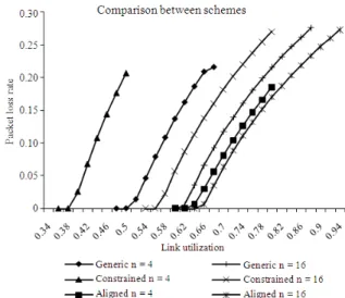
Fig. 13: Comparison between the three schemes for n = 4 and n = 16
occur at the next switch. Let’s refer the above condition to as the ∆Tail-condition. It should be noted that the entire packet stream departing from an output of a switch must always satisfy the ∆Tail-condition in nature. Therefore, we can conclude that the head-tail clashing can be totally eliminated in the VPFS network with alignment, as long as the traffic from all sources satisfy the ∆Tail -condition.
Figure 13 provides the comparison between the three VPFS schemes, considering the same model as discussed earlier. It is obvious that the performance of the switch with alignment improves dramatically when compared to the constrained VAPFA model and also a marked improvement over the generic unconstrained VAPFA. For example, when n = 16, the packet loss begins only at U = 0.62. Another interesting observation is, when n becomes larger, the performances of the three VPFS schemes get closer.
CONCLUSION
schemes. One of the main issues of the VAPFA algorithm is the time complexity when selecting a small slot size for the VPFS network.
REFERENCES
Chao, H.J. and F.S. Choa, 1999. All-optical packet routing-Architecture and implementation. J. Photon. Network. Commun., 1: 303-311. DOI: 10.1023/A:1010074700412
Chao, H.J. and S.Y. Liew, 2003. A new optical cell switching paradigm. Proceeding of the International Workshop Optical Burst Switching, Oct. 2003. Dallas, TX., pp: 1270-134. http://www.cse.buffalo.edu/~qiao/wobs/wobs2003/ files/WOBS106OCS.pdf
Chao, H.J. et al., 2000. Aphotonic front-end processor in aWDMATMmulticast switch. J. Lightweight Technol., 18: 273-285.
Chia, M.C. et al., 2001. Packet loss and delay performance of feedback and feed-forward arrayed-waveguide gratings-based optical packet switches with WDM inputs-outputs. J. Lightweight Technol., 19: 1241-1254.DOI: 10.1109/50.948271 Guillemot, C. et al., 1998. Transparent optical packet
switching: The European ACTS KEOPS project approach. J. Lightweight Technol., 16: 2117-2134. http://dces.essex.ac.uk/staff/hunter/Guillemot%20J LT%20Dec98.pdf
Hiroaki, H. and M. Masayuki, 2006. Optical fiber-delay-line buffer management in output-buffered photonic packet switch to support service differentiation. IEEE J. Select. Areas Commun., 24: 108-116. DOI:10.1109/JSAC.2006.1677258 Hiroaki, H., S. Motoshi and O. Takeshi, 2006. Buffer
management for shared feedback buffer-type optical packet switches. Proc. IEEE ICC., 6: 2574-2580. DOI:10.1109/ICC.2006.255167 Hunter, D.K., M.C. Chia and I. Andonovic, 1998.
Buffering in optical packet switches. J. Lightweight Technol., 16: 2081-2094. http://citeseerx.ist.psu.edu/viewdoc/summary?doi= 10.1.1.25.2990
Hunter, D.K., W.D. Cornwell, T.H. Gilfedder, A. Franzen and I. Andonovic, 1998. SLOB: A switch with large optical buffers for packet switching. J. Lightw. Technol., 16: 1725-1736. http://cat.inist.fr/?aModele=afficheN&cpsidt=2415 532
Jason, P.J., 2000. Multiconfiguration multihop protocols: A new class of protocols for packet-switched WDM optical networks. IEEE/ACM Trans. Network., 8: 631-642. DOI: 10.1109/90.879349
Karol, M.J., 1993. Shared-memory optical packet (ATM) switch. Proc. SPIE., 2024: 212. DOI: 10.1117/12.161326
Liew, S.Y., H. Gang and C. Jonathan, 2005. Scheduling algorithms for shared fiber-delay-line optical packet switches-Part I: The single-stage case. J. Lightweight Technol., 23: 1586-1600. DOI: 10.1109/JLT.2005.844196
Liew, S.Y., T. Andrew and T. Robert, 2007. On all-optical packet switching without synchronizer. IEEE ICICS., 2007: 126-137.
Masetti, F., P.
Gavignet-Morin, D. Chiaroni and G. DaLoura, 1993. Fiber delay lines optical buffer for ATM photonic switching applications. Proceedings of the 20th Annual Joint Conference of the IEEE Computer and Communications Societies on Networking: Foundation for the Future, Mar. 28-Apr. 1, San Francisco, CA., USA., pp: 935-942. DOI: 10.1109/INFCOM.1993.253273 Ramamirtham, J. and J. Turner, 2003. Time sliced optical burst switching. Proceeding of the 22nd Annual Joint Conference on IEEE Computer and Communications Societies, Mar. 30-Apr. 3, San Francisco, CA, USA., pp: 2030-2038. http://ieeexplore.ieee.org/xpl/freeabs_all.jsp?arnum ber=1209224
Shi, J., 2005. Scheduling algorithms for shared fiber-delay-line optical packet switches-Part II: The Three-stage clos-network case. J. Lightweight
Technol., 23: 1601-1609.
http://cat.inist.fr/?aModele=afficheN&cpsidt=1669 5676
Wong, E.S., 2006. Action research: A Post-Structural and Post-Modern Dissertation. Centre of Reflective Practitioner Resources Publication, Perth, Australia. ISBN: 0-9775005-1-9, pp: 97-102. Wong, E.S., 2007. Action Research in Social Science,