TCD
7, 4501–4544, 2013Fracture-induced softening in ice
dynamics
T. Albrecht and A. Levermann
Title Page
Abstract Introduction
Conclusions References
Tables Figures
◭ ◮
◭ ◮
Back Close
Full Screen / Esc
Printer-friendly Version Interactive Discussion
Discussion
P
a
per
|
Dis
cussion
P
a
per
|
Discussion
P
a
per
|
Discussio
n
P
a
per
|
The Cryosphere Discuss., 7, 4501–4544, 2013 www.the-cryosphere-discuss.net/7/4501/2013/ doi:10.5194/tcd-7-4501-2013
© Author(s) 2013. CC Attribution 3.0 License.
Geoscientiic Geoscientiic
Geoscientiic Geoscientiic
Open Access
The Cryosphere
Discussions
This discussion paper is/has been under review for the journal The Cryosphere (TC). Please refer to the corresponding final paper in TC if available.
Fracture-induced softening for large-scale
ice dynamics
T. Albrecht1,2and A. Levermann1,2
1
Earth System Analysis, Potsdam Institute for Climate Impact Research, Potsdam, Germany
2
Institute of Physics and Astronomy, University of Potsdam, Potsdam, Germany
Received: 20 August 2013 – Accepted: 20 August 2013 – Published: 9 September 2013
Correspondence to: A. Levermann ([email protected])
TCD
7, 4501–4544, 2013Fracture-induced softening in ice
dynamics
T. Albrecht and A. Levermann
Title Page
Abstract Introduction
Conclusions References
Tables Figures
◭ ◮
◭ ◮
Back Close
Full Screen / Esc
Printer-friendly Version Interactive Discussion
Discussion
P
a
per
|
Dis
cussion
P
a
per
|
Discussion
P
a
per
|
Discussio
n
P
a
per
|
Abstract
Floating ice shelves can exert a retentive and hence stabilizing force onto the inland
ice sheet of Antarctica. However, this effect has been observed to diminish by
fracture-coupled dynamic processes within the protective ice shelves leading to accelerated ice flow and hence to a sea-level contribution. In order to better understand the role of 5
fractures in ice dynamics we apply a large-scale continuum representation of fractures and related fracture growth into the prognostic Parallel Ice Sheet Model (PISM). To this end we introduce a higher-order accuracy advection scheme for the transport of the two-dimensional fracture density across the regular computational grid. Dynamic
coupling of fractures and ice flow is attained by a reduction of effective ice viscosity
10
proportional to the inferred fracture density. This formulation implies the possibility of a non-linear threshold behavior due to self-amplified fracturing in shear regions triggered by small variations in damage threshold. As a result of prognostic flow simulations, flow patterns with realistically large across-flow velocity gradients in fractuweakened re-gions as seen in observations are reproduced. This model framework is expandable to 15
grounded ice streams and accounts for climate-induced effects on fracturing and hence
on the ice-flow dynamics. It further allows for an enhanced fracture-based calving pa-rameterization.
1 Introduction
The contemporarily observed sea-level change (Cazenave and Llovel, 2010; Church 20
et al., 2011; Gregory et al., 2012) as well as the expected long-term sea-level commit-ment (Levermann et al., 2013) underpin the role of the contributions of the large polar ice sheets of Greenland and Antarctica (Van den Broeke et al., 2011; Rignot et al., 2011b; Shepherd et al., 2012; Hanna et al., 2013). Reliable and accurate process-based models are required to understand the involved complex processes and to pro-25
TCD
7, 4501–4544, 2013Fracture-induced softening in ice
dynamics
T. Albrecht and A. Levermann
Title Page
Abstract Introduction
Conclusions References
Tables Figures
◭ ◮
◭ ◮
Back Close
Full Screen / Esc
Printer-friendly Version Interactive Discussion
Discussion
P
a
per
|
Dis
cussion
P
a
per
|
Discussion
P
a
per
|
Discussio
n
P
a
per
|
aspects of ice flow need a better representation in these models to account for the potential destabilization of key regions, such as the West Antarctic Ice Sheet (Bam-ber et al., 2009; Joughin and Alley, 2011). The retentive force of floating ice shelves that retains the oceanward ice flow (Dupont and Alley, 2005; Winkelmann et al., 2012; Gudmundsson, 2013) is of high relevance in this assessment. Most models neglect 5
fracture-coupled processes, which can repeal this buttressing effect of ice shelves.
Fracture processes play a fundamental role in the dynamics of ice streams and ice shelves, interacting with external drivers such as ocean melt or atmospheric warming (Pritchard et al., 2012; Rignot et al., 2013; MacAyeal and Sergienko, 2013). Fractures are mostly found as elongated structures of fragments or sequences of troughs and 10
open crevasses, visible at the ice surface. These fracture bands are aligned along the ice flow with origin in the wake of topographic features such as ice rises, ice rumples or along ice stream inlets and usually expand the whole distance towards the calving front. On that journey along the stream, prevailing stresses can change and activate crevasses and rift formation. Such deep-reaching ruptures were observed to propagate 15
horizontally up to 100 km long across flow units (Hulbe et al., 2010).
Fractures and ice flow interact in various ways. Considering one effective direction,
certain dynamic regimes promote the formation of fractures. More precisely, they form in regions of strong shear or tensile flow for certain temperature and ice conditions. External forces such as seasonal meltwater drainage can enhance the vertical propa-20
gation of existing surface fractures (Weertman, 1973; Van der Veen, 1998a), but snow
drift, refreezing or recrystallization can cover and heal them. Similar effects underneath
the ice shelf influence the formation and propagation of basal crevasses, which can reach far upward, producing a trough at the surface by viscous adjustment (Van der Veen, 1998b; McGrath et al., 2012b; Luckman et al., 2012; Vaughan et al., 2012). 25
Considering the other effective direction, the abundance of fractures potentially affect
the flow regime since horizontal (membrane) stresses cannot be effectively transferred
TCD
7, 4501–4544, 2013Fracture-induced softening in ice
dynamics
T. Albrecht and A. Levermann
Title Page
Abstract Introduction
Conclusions References
Tables Figures
◭ ◮
◭ ◮
Back Close
Full Screen / Esc
Printer-friendly Version Interactive Discussion
Discussion
P
a
per
|
Dis
cussion
P
a
per
|
Discussion
P
a
per
|
Discussio
n
P
a
per
|
snapshot quantification of the dynamic activity of mechanically weakened areas associ-ated with fractures. Between those partly detached flow units, strong velocity gradients and consequently intense shear is observed, which cannot be reproduced in standard ice-flow models (discussed in Sandh ¨ager et al., 2005; Humbert et al., 2009).
Hence, this interaction of flow and fracture dynamics characterizes a self-amplifying 5
feedback mechanism that is susceptible to changes in external conditions (Scambos et al., 2000, 2003; MacAyeal et al., 2003). Melting and hydro-fracturing causes en-hanced structural weakening of the mechanical integrity in fractured regions (Scambos et al., 2009; Glasser and Scambos, 2008; Vieli et al., 2007; Khazendar et al., 2007; Van der Veen, 2007; McGrath et al., 2012a). This reduces the lateral support of the 10
confinement and consequently the buttressing, leading to a speedup of interior
ice-shelf flow units, draining more efficiently the upstream glaciers (Rignot et al., 2004;
Rott et al., 2011). Stronger shear and thinning in turn supports fracturing, which ul-timately can destabilize the entire ice shelf, as observed in several cases along the Antarctic Peninsula (Cook and Vaughan, 2010).
15
Fracturing of ice represents a key process in the description of the complex ice-flow pat-tern and plays an important role in ice-shelf calving (Benn et al., 2007) and abrupt dis-integration. Particle-flow models may provide a novel and promising representation of fracture formation and related iceberg calving (Bassis and Jacobs, 2013). In this study we present a simplified framework of continuum damage evolution based on ideas 20
by Pralong and Funk (2005) adapted to the finite-difference Parallel Ice Sheet Model
(Bueler and Brown, 2009; Winkelmann et al., 2011, based on PISM v.05; see docu-mentation: www.pism-docs.org). In the first part we briefly resume the assumptions and methods of identifying regions of fracture initiation and corresponding damage ac-cumulation, which has been described in detail in Albrecht and Levermann (2012). A 25
simple coupling relation of fracture density and viscous-ice deformation is then
intro-duced and justified. Inherent non-linear effects such as multi-stability are
observa-TCD
7, 4501–4544, 2013Fracture-induced softening in ice
dynamics
T. Albrecht and A. Levermann
Title Page
Abstract Introduction
Conclusions References
Tables Figures
◭ ◮
◭ ◮
Back Close
Full Screen / Esc
Printer-friendly Version Interactive Discussion
Discussion
P
a
per
|
Dis
cussion
P
a
per
|
Discussion
P
a
per
|
Discussio
n
P
a
per
|
tions provides a tool for calibrating employed parameters and thresholds and identifying
qualitative differences in the flow field, introduced by the fracture-flow coupling. A
con-cluding discussion summarizes the findings and reveals limitations of the approach and also future applications, such as a fracture-induced calving parameterization.
2 The fracture density concept
5
The basic idea of the continuous, dynamically evolving fracture-density field, applied to ice shelves, has been introduced by Albrecht and Levermann (2012). The scalar
value of the isotropic damage variable, 0≤φ≤1, called “fracture density”, has been
interpreted as a measure for the density of macroscopic but subgrid-scale fracture
features per ice-shelf area. As a field variable,φcan be transported with the ice flow
10
v as
∂φ
∂t +v· ∇φ=fs+fh. (1)
In this simple advection equationfs andfhindicate the source and sink terms.
In areas, where a certain fracture-initiation thresholdσcris exceeded,φis assumed to
grow with a rate that is proportional to the local maximum spreading rate, ˙ǫ+. This
func-15
tional relationship accounts for the probability for the initiation of new fractures within a grid cell area and hence for fracture accumulation. Since brittle fractures, e.g., sur-face and bottom crevasses, are likely produced in previously cracked regimes, we here
consider the aggregated effect, not distinguishing between individual fracture
repre-sentations. The presence of densely-spaced fractures however restricts the probability 20
for additional fracture formation by reducing the overall stress field in their proximity,
which is expressed simply by a reducing factor, 1−φ, in the damage evolution function
fs=
(
γ·ǫ˙+·(1−φ), σt≥σcr
0, σt< σcr
TCD
7, 4501–4544, 2013Fracture-induced softening in ice
dynamics
T. Albrecht and A. Levermann
Title Page
Abstract Introduction
Conclusions References
Tables Figures
◭ ◮
◭ ◮
Back Close
Full Screen / Esc
Printer-friendly Version Interactive Discussion
Discussion
P
a
per
|
Dis
cussion
P
a
per
|
Discussion
P
a
per
|
Discussio
n
P
a
per
|
Damage contributions are expected in regions where the “effective-stress” ellipse,
de-fined in terms of surface-parallel principal stresses,σ+andσ−, as
σt=
q
σ+2+σ−2−σ+σ−, (3)
exceeds the von-Mises critical strength σcr (von Mises, 1913; Vaughan, 1993). The
fracture-density variable is then carried downstream with the ice velocity (here following 5
the Shallow Shelf Approximation in Eq. (1)).
Existing fractures can experience deactivation by recrystallization, snow cover or closure in moderate stress environments, expressed in a healing rate,
fh=
(
γh·( ˙ǫ+−ǫ˙h), ǫ˙+≤ǫ˙h
0, ǫ˙+>ǫ˙h
. (4)
Depending on the local tensile strain-rate condition, ˙ǫ+≤ǫ˙h, the advected fracture
den-10
sity is then reduced with the constant rate factor,γh. Sensitivity of the fracture field to
these parameters and their role for the fracture density have been evaluated in Albrecht and Levermann (2012). In the following we apply the fracture density to the ice viscosity to allow for a feedback onto the flow field.
3 Fracture-induced softening
15
In this section we build on recent efforts and investigate the feedback mechanism of
fracture formation and its cumulative imprint on the flow dynamics within a framework that is based on a simplified version of continuum damage mechanics (Pralong and Funk, 2005; Duddu and Waisman, 2012a,b). A high frequency of fractures reduces the integrity of the ice body and stresses cannot be transferred properly any more, hence 20
TCD
7, 4501–4544, 2013Fracture-induced softening in ice
dynamics
T. Albrecht and A. Levermann
Title Page
Abstract Introduction
Conclusions References
Tables Figures
◭ ◮
◭ ◮
Back Close
Full Screen / Esc
Printer-friendly Version Interactive Discussion
Discussion
P
a
per
|
Dis
cussion
P
a
per
|
Discussion
P
a
per
|
Discussio
n
P
a
per
|
distinct dynamic characteristics. From a macroscopic point of view, this dynamic
decou-pling corresponds to a softening effect of the ice that can be expressed in the model as
a modified flow-enhancement factorEA(Humbert, 2006; Humbert et al., 2009).
Assum-ing the strain-equivalence between physical and effective spaces (Pralong and Funk,
2005; Duddu and Waisman, 2012a; Borstad et al., 2013), the stress-balance equation 5
remains unchanged with a modified effective viscosity defined as
ηφ=E
−1 n
A ·
1 2·ǫ˙
1−n n e
Z
B(T)d z
. (5)
Here,B(T) denotes ice hardness (or rigidity), which depends on the vertical
temper-ature distribution,T =T(z). The effective strain rate, ˙ǫe, is the second invariant of the
10
strain-rate tensor (equivalent to the effective stress in Eq. (3)), with n=3, Glen’s flow
law parameter.
We assume a simple functional relationship for the fracture-density induced softening, written as
EA=ESSA·[ 1−(1−ε)·φ]−n ε
=0
−→ESSA·[ 1−φ]−n. (6)
15
For its implementation in the numerical model we introduce the parameterεas a lower
limit for the softening, avoiding a degeneration of the equations. In the simulations
presented here epsilon isε=0.001. The SSA-enhancement factor,ESSA, is commonly
used in ice modeling and comprises anisotropy and other softening effects of the intact
ice (Ma et al., 2010; Winkelmann et al., 2011). However,ESSA is taken to be constant
20
in space and time.
The influence of the two unitless parameters on the emerging non-linear coupling
is shown in Fig. 1. For a fracture density of φ=0.5 and, hence half the undamaged
viscosity, ice is softened by a factorEA=5 up toEA=8. This is realistic for commonly
used rate factorsESSA(left-hand panel). Due to the strong non-linearity, this factor is
al-25
most an order of magnitude larger (35≤EA≤60) for a fracture density ofφ=0.75 and
TCD
7, 4501–4544, 2013Fracture-induced softening in ice
dynamics
T. Albrecht and A. Levermann
Title Page
Abstract Introduction
Conclusions References
Tables Figures
◭ ◮
◭ ◮
Back Close
Full Screen / Esc
Printer-friendly Version Interactive Discussion
Discussion
P
a
per
|
Dis
cussion
P
a
per
|
Discussion
P
a
per
|
Discussio
n
P
a
per
|
behavior approaching vanishing viscosity, which seems ambiguous in the framework of continuum mechanics. In this regime of fracture densities close to 1, the comparably
small residual valueεlimits ice softness to guarantee convergence of the stress
bal-ance calculation. The proposed functional relationship is a crude estimate based on plausibility arguments and needs to be quantitatively characterized.
5
The proposed model framework implies a potentially self-amplifying feedback mecha-nism: If fractures form in a certain region, the ice will be softened according to Eq. (6), which allows for a concentration of shear. This applies also in regions downstream of the formation area where the fractures are transported to. Stronger shear increases the
effective stress and if the initiation threshold is hit, additional fractures can form leading
10
to an increasing fracture density there. Healing and numerical diffusion counteract the
accumulation of damage, which otherwise would tend to approach asymptotically the upper bounding value 1.
4 Methods
4.1 Evaluating fracture initiation criteria
15
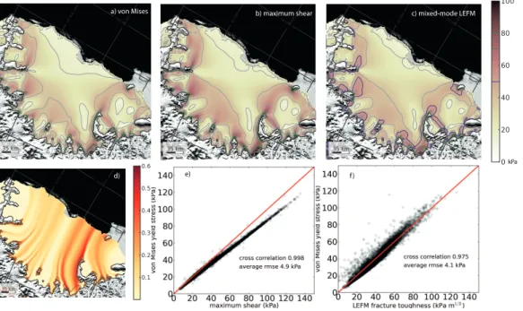
Failure of ice occurs at stresses beyond certain thresholds and is hence often ex-pressed in terms of material strength. There is a variety of phenomenological standard failure criteria for the identification of regions where fracturing potentially occurs. We
use the von-Mises criterion based on the maximum effective stress exceeding a critical
value (Eq. 3), which is equivalent to the exceedance of a maximal distortion energy 20
(von Mises, 1913; Vaughan, 1993). This criterion is very similar to the maximum shear stress criterion (a.k.a. Tresca or Guest criterion in literature)
σms=max (|σ+|,|σ−|,|σ+−σ−|). (7)
In a computational setup of the Larsen C Ice Shelf with a resolution of 1.75 km, this
maximum shear stress is about 15% larger than the effective stress used in the
TCD
7, 4501–4544, 2013Fracture-induced softening in ice
dynamics
T. Albrecht and A. Levermann
Title Page
Abstract Introduction
Conclusions References
Tables Figures
◭ ◮
◭ ◮
Back Close
Full Screen / Esc
Printer-friendly Version Interactive Discussion
Discussion
P
a
per
|
Dis
cussion
P
a
per
|
Discussion
P
a
per
|
Discussio
n
P
a
per
|
Mises criterion (Fig. 2 b, e). If the corresponding threshold is reduced by 15% with
respect to the von-Mises strength (σt≥70 kPa and σms≥80 kPa coincide with 95%)
fracture formation is initiated in the same regions and very similar steady-state patterns of fracture density evolve.
A more sophisticated fracture-initiation criterion, derived from Linear Elastic Fracture 5
Mechanics (LEFM), takes into account both shear and tensile modes of cracking in a biaxial stress field. Following this approach, a single crevasse forms when the critical
fracture toughnessKIc is exceeded by the combined stress intensities, defined as
KIc≤
√
π c
σncos3
θ
2
+τscos
θ
2
sin (θ)
, (8)
with θ=−2 arctan
q
σn2+8τs2−σn 4τs
. (9)
10
The parameter cdenotes the half-length of preexisting edge cracks, σn is the stress
across to the crack opening andτs the shear stress along the crack planes (see
Er-dogan and Sih (1963); Shyam Sunder and Wu (1990); Rist et al. (1999); Hulbe et al. (2010) for details). The fracture toughness for a given geometry of preexisting flaws 15
is density-dependent. For the low-density firn at the surface, a fracture toughness of
KIc≈50 kPa
√
m was obtained in laboratory experiments with ice core specimen from
the Ronne Ice Shelf (Rist et al., 1999, 2002). Larger values ofKIc≈150 kPa
√
m or more are expected for the meteroric or marine ice at the ice shelf bottom. For fracture fields of narrow-spaced crevasses, the fracture toughness can even be twice or triple as high 20
as for intact ice (Van der Veen, 1998a). It appears that the initial crack half-length c
is a weakly confined parameter. We assigned a value ofc=0.2 m, such that the root
mean square error in comparison to the von-Mises criterion becomes minimal within the computational setup of the Larsen C region (Fig. 2 f). Jansen et al. (2010) indicate a unique pattern of potential crevasse opening for a given ratio of fracture toughness 25
TCD
7, 4501–4544, 2013Fracture-induced softening in ice
dynamics
T. Albrecht and A. Levermann
Title Page
Abstract Introduction
Conclusions References
Tables Figures
◭ ◮
◭ ◮
Back Close
Full Screen / Esc
Printer-friendly Version Interactive Discussion
Discussion
P
a
per
|
Dis
cussion
P
a
per
|
Discussion
P
a
per
|
Discussio
n
P
a
per
|
of 50 kPa√m). Since the relevant brittle fracture-formation areas coincide mostly with
those identified with the ductile von-Mises criterion (forKIc=70 kPa
√
m andσt≥70 kPa
fracture-formation area have a 75% match), the fracture density pattern does not show
major differences at the resolutions applied here. Hence, in the following study we use
the von-Mises criterion only. 5
A similar approach based on LEFM was proposed by Van der Veen (1998a,b) for the investigation of vertical crack propagation of both surface and bottom crevasses but only for tensile crack modes. An accurate estimate of the maximal fracture depth requires accurate data of the vertical profiles of ice density and other physical param-eters (Rist et al., 2002; Plate et al., 2012). This approach of vertical fracture extension 10
will not be further discussed in this study and might be part of future studies.
4.2 Feature-preserving two-dimensional numerical advection scheme
Standard first-order upstream differencing schemes are a commonly applied pragmatic
choice to approximate hyperbolic-type partial differential equations as the advection
equation in Eq. (1) (e.g., Press et al., 2009). However, these schemes are known to 15
be numerically dissipative. Especially for plane flow that is oblique with respect to the underlying grid (“zigzag” course from cell to cell), it tends to smear out well-defined structures of high fracture density on their way downstream, which can be associated with an angle-dependent healing for unphysical reasons. Therefore we implemented an upstream transport scheme of higher-order accuracy such that the gradient, cor-20
TCD
7, 4501–4544, 2013Fracture-induced softening in ice
dynamics
T. Albrecht and A. Levermann
Title Page
Abstract Introduction
Conclusions References
Tables Figures
◭ ◮
◭ ◮
Back Close
Full Screen / Esc
Printer-friendly Version Interactive Discussion
Discussion
P
a
per
|
Dis
cussion
P
a
per
|
Discussion
P
a
per
|
Discussio
n
P
a
per
|
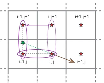
eight different cases depending on the flow angle,
φN+1=φN−∆t·
u(φi,j−φi−1,j)/∆x+v(φi−1,j−φi−1,j−1)/∆y, 0≤v∆x/∆y≤u
u(φi,j−1−φi−1,j−1)/∆x+v(φi,j−φi,j−1)/∆y, 0≤u∆y/∆x≤v
−u(φi,j−1−φi+1,j−1)/∆x+v(φi,j−φi,j−1)/∆y, 0≥u∆y/∆x≥ −v
−u(φi,j−φi+1,j)/∆x+v(φi+1,j−φi+1,j−1)/∆y, 0≤v∆x/∆y≤ −u
−u(φi,j−φi+1,j)/∆x−v(φi+1,j−φi+1,j+1)/∆y, 0≥v∆x/∆y≥u
−u(φi,j+1−φi+1,j+1)/∆x−v(φi,j−φi,j+1)/∆y, 0≥u∆y/∆x≥v u(φi,j+1−φi−1,j+1)/∆x−v(φi,j−φi,j+1)/∆y, 0≤u∆y/∆x≥ −v
u(φi,j−φi−1,j)/∆x−v(φi−1,j−φi−1,j+1)/∆y, 0≥v∆x/∆y≥ −u,
(10)
whereNindicates the time step whilei andjare the coordinates on the regular
rectan-gular grid (see Fig. 3). This modification improves the representation of advection in two
dimensions and exhibits much less numerical diffusion for transport that is oblique with
5
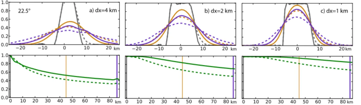
respect to the grid axes. Figure 4 shows three transects perpendicular and along the symmetry flowline in a simplified ice-shelf setup of 100 km width and length. Fracture
density as a tracer is initialized with unity value within a small domain of 8×8 km.
The-oretically a narrow band of constant fracture density is expected downstream. In fact,
if the flow direction coincides with one grid axis, numerical diffusion can be neglected
10
for both schemes (Fig. 4 a). When turning the main flow direction by 45◦ the higher
order scheme reveals a very high accuracy as in the unturned case. In contrast, for the first order scheme, maximum values are reduced to about 40% of its initial value over a distance of 90 km (dashed profile in Fig. 4 b). For the flow that is turned by intermediate
angles, such as 22.5◦, both schemes show an unintended numerical diffusion, but
sig-15
TCD
7, 4501–4544, 2013Fracture-induced softening in ice
dynamics
T. Albrecht and A. Levermann
Title Page
Abstract Introduction
Conclusions References
Tables Figures
◭ ◮
◭ ◮
Back Close
Full Screen / Esc
Printer-friendly Version Interactive Discussion
Discussion
P
a
per
|
Dis
cussion
P
a
per
|
Discussion
P
a
per
|
Discussio
n
P
a
per
|
4.3 Fracture formation along grounded ice streams
Fractures are often observed to be initiated in the rocky shear margins of the inlets upstream from the grounding line, where ice flow accelerates due to decreased
basal friction. The boundary condition for the fracture-density evolution, φ0, is
applied along the grounding line that confines the ice shelf domain. In this way, 5
φ0, accounts for pre-existing fractures draining through the inlets. We assume that
fracture processes in grounded but “shelfy” regions occur under similar conditions as within the ice shelf domain. In this way we can calculate contributions to the fracture density field from observed velocities in the grounded regions as prescribed boundary
condition along the grounding line, yielding a more realisticφ0than in a previous study.
10
4.4 Interpreting fracture density from satellite visible imagery
In order to compare the modeled fracture density with observations, we hand-digitized visible surface features that seem to represent fracture phenomena of any kind. We identified these features in MOA satellite spectroradiometer images of the largest 15
Antarctic ice shelves as snapshot of the years 2003 to 2004 (Scambos et al., 2007, MODIS Mosaic of Antarctica). Recent observation have shown that observed surface troughs in ice shelves often correspond to widely spaced basal crevasses, which
sup-port surface fracturing by viscous-adjustment induced bending effects (McGrath et al.,
2012b; Luckman et al., 2012; Vaughan et al., 2012). However, the smaller surface 20
crevasses as well as the highly fragmented shear zones are hard to identify from satel-lite data for resolutions of 150 m, especially when snow-covered. Here we do not
dis-tinguish between the different representations (Glasser and Scambos, 2008; Glasser
et al., 2009).
Following Albrecht and Levermann (2012), we calculated a two-dimensional represen-25
tation of the observed fracture features,φobs, for each grid cell of a given resolution,
moti-TCD
7, 4501–4544, 2013Fracture-induced softening in ice
dynamics
T. Albrecht and A. Levermann
Title Page
Abstract Introduction
Conclusions References
Tables Figures
◭ ◮
◭ ◮
Back Close
Full Screen / Esc
Printer-friendly Version Interactive Discussion
Discussion
P
a
per
|
Dis
cussion
P
a
per
|
Discussion
P
a
per
|
Discussio
n
P
a
per
|
vated by the fact that, for crevasse opening perpendicular to the the main tensile stress axis, the applied far-field stress has to circumvent the discontinuity. This reduces the
effective stress to both sides of the crack, acting as a stress shadow cast.
Additionally, the inferred observed fracture density was smoothed with a running mean along the flowline, which is derived from the modeled/observed velocity field. 5
This along-flowline spatial smoothing of the monitored snapshot mimics a time average and reveals more clearly the continuous band structure of observed fractures, e.g., in suture zones and along shear margins (see Fig. 6). Apparently, this mapping procedure cannot give a precise and complete picture of the dynamically relevant observed fracture regions, but it gives an impression of the rough pattern of fracture 10
abundance and accumulation for a qualitative validation.
4.5 Computational setup and settings
The simulations of the Antarctic ice shelves that we performed are based on high-resolution datasets. Ice thickness, bed-topography data and the grounding-line position 15
are described in the Bedmap2 product on a 1 km grid in polar stereographic projection (Fretwell et al., 2013). In order to avoid grounding in shallow ice-shelf areas, the sub-shelf seabed elevation is arbitrarily set to 2000 m depth. Climatic mass balance and ice-surface temperature are available from ALBMAP v1 on a 5 km grid (Le Brocq et al., 2010). FESOM data (melting and refreezing rates beneath the ice shelf), averaged 20
over the historical period 1960 to 1999, were kindly provided on an unstructured grid with resolutions of up to 4 km by Timmermann et al. (2012); Timmermann and Hellmer (2013). Surface-velocity data covering the whole Antarctic continent has been assem-bled by Rignot et al. (2011a) from multiple satellite interferometric radar data of the years 2007 to 2009. The data are used for validation and as Dirichlet boundary con-25
TCD
7, 4501–4544, 2013Fracture-induced softening in ice
dynamics
T. Albrecht and A. Levermann
Title Page
Abstract Introduction
Conclusions References
Tables Figures
◭ ◮
◭ ◮
Back Close
Full Screen / Esc
Printer-friendly Version Interactive Discussion
Discussion
P
a
per
|
Dis
cussion
P
a
per
|
Discussion
P
a
per
|
Discussio
n
P
a
per
|
Since the datasets are a product of a period after the breakup of Larsen A and B Ice Shelves, the input data has been modified for this region according to a period prior to it (Jezek et al., 2003, Modified Antarctic Mapping Mission (MAMM)). Initial ice thickness in the embayment was inferred from surface elevation data on a 2 km grid with applied firn-correction (Lythe et al., 2001). Provided MAMM surface velocities of 5
the time period 1997 to 2000 for validation exhibit gaps that has been filled using an SOR method for the Laplace equation. For the inlets Dirichlet boundary conditions are based on the latest observations by Rignot et al. (2011a).
For the computational setup of the Pine Island and Thwaites region the boundary is defined along the inner-continental ice divide separating the drainage basin. Within 10
this basin the stress balance is solved additionally in Shallow Ice Approximation (SIA) superposing the SSA for a prescribed basal friction field, which is a combination of PISM-internal parameterizations (Winkelmann et al., 2011) and inversely inferred data, provided courtesy of Ian Joughin.
Iceberg calving is not considered in the simulations. The ice flow is simply cut off at
15
the initial ice-shelf front. Friction along side margins and ice rises is not explicitly set as in previous studies since it inherently results from ice thickness and velocity along the boundary. Fracture initiation is considered also in the grounded region as deter-mined by the prescribed velocities based on observations and is transported across the grounding line into the ice-shelf domain. Density within the ice is prescribed with a 20
constant value of 910 kg m−3.
A simplified computational setup is used with an ice shelf confined in a rectangular bay of 100 km width and 2000 m depth. Constant ice inflow is defined at the upper
ground-ing line with 600 m thickness and 300 m yr−1speed while the side margins are ice-free
walls. Surface temperature is constantly -30◦C and surface-mass balance 0.1 m yr−1
25
TCD
7, 4501–4544, 2013Fracture-induced softening in ice
dynamics
T. Albrecht and A. Levermann
Title Page
Abstract Introduction
Conclusions References
Tables Figures
◭ ◮
◭ ◮
Back Close
Full Screen / Esc
Printer-friendly Version Interactive Discussion
Discussion
P
a
per
|
Dis
cussion
P
a
per
|
Discussion
P
a
per
|
Discussio
n
P
a
per
|
5 Results
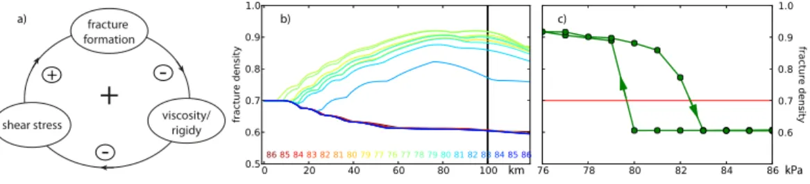
5.1 Self-amplified fracturing
Non-linear systems may exhibit bistable phenomena based on a positive, i.e. self-amplifying, feedback loop as proposed previously in the text (Sect. 3). On large cli-matic scales, systems that exhibit such behavior are sometimes called “tipping ele-5
ments” (Levermann et al., 2011). Here this characteristic behavior is investigated in a simplified experiment where within a confined ice shelf region (a few grid cells)
frac-ture density ofφ=0.7 is prescribed, which imitates a constantly active fracture source.
The damaged ice is carried with the flow downstream and decays slightly by diffusive
healing as long as the effective stress stays below the fracture-initiation threshold,σcr.
10
If this spot is situated in a shearing flow field, the damage-induced softening intensifies
the shear and hence the effective stress. In the experiment we gradually decreaseσcr,
which corresponds to additional forcing supporting fracture formation, such as
meltwa-ter infiltration. If the effective stress hits a specific threshold (here σcr<80 kPa)
addi-tional fractures form and accumulate downstream of the initial point (see the jump in 15
Fig. 7). This in turn increases the effective stress in this confined area, leading to the
plotted steady state profiles. If environmental conditions reverse, such that the fracture
thresholdσcrincreases, we observe a jump back to the former state of a weakly
decay-ing fracture band forσcr>82 kPa, thus revealing a classic hysteresis behavior. This is a
robust feature and is also found in more realistic setups representing relevant Antarctic 20
Ice Shelves.
5.2 Application to Antarctic ice shelves and subregions
In the following the various aspects of fracture-softening are investigated in exemplary ice shelf sub-regions of the largest Ross and Ronne-Filchner Ice Shelves (see colored rectangles in Fig. 6). The smaller northern-most Larsen Ice Shelves along the Antarctic 25
TCD
7, 4501–4544, 2013Fracture-induced softening in ice
dynamics
T. Albrecht and A. Levermann
Title Page
Abstract Introduction
Conclusions References
Tables Figures
◭ ◮
◭ ◮
Back Close
Full Screen / Esc
Printer-friendly Version Interactive Discussion
Discussion
P
a
per
|
Dis
cussion
P
a
per
|
Discussion
P
a
per
|
Discussio
n
P
a
per
|
are performed on a 1 km regular grid. Parameters are roughly estimated such that the qualitative changes become apparent for each individual setup.
5.2.1 Byrd Inlet in Ross Ice Shelf
The Byrd inlet is an important inflow for the Ross Ice Shelf, draining though a narrow trough of the Transantarctic mountains (Fig. 8 a). From there the ice flows as a homo-5
geneous unit at about 600 m yr−1 eastwards through slow moving ice that is confined
within the embayment of Ross Island. The cross section right after the entrance of the inlet shows steep velocity gradients especially on the northern side. A constant flow
en-hancementESSA=0.4 yields reasonable results for simulations of the whole Ross Ice
Shelf domain. The corresponding profile perpendicular to the main flow direction, how-10
ever, shows a smooth transition between the broad inflow unit and the much slower surrounding ice (light blue in Fig. 8 c), but it does not allow for the intense observed shear flow. In contrast, fracture-softening reveals highly fractured bands on both sides of the inlet (Fig. 8 b), confining the fast flow unit, with strong gradients at its flanks (vio-let profile in Fig. 8 c). However, the resulting profile appears to be shifted transversally 15
by about 15 km, which might be caused by underestimated inflow through the south-ern boundary of the computational domain, which forces the incoming stream north-wards. The orange contour lines in Fig. 8 b indicate that fractures form already in the
grounded upstream inlet channel, where the von-Mises effective stress is larger than
110 kPa. This fracture band partly detaches the flow from the topographical promontory 20
further downstream (Pr), which otherwise would act as fracture-formation area. Heal-ing is comparably small but fracture density vanishes within about 100 km distance as suggested by observations in this area. The basic flow enhancement for intact ice in
the remaining computational domain is very much reduced (ESSA=0.05) in order to
TCD
7, 4501–4544, 2013Fracture-induced softening in ice
dynamics
T. Albrecht and A. Levermann
Title Page
Abstract Introduction
Conclusions References
Tables Figures
◭ ◮
◭ ◮
Back Close
Full Screen / Esc
Printer-friendly Version Interactive Discussion
Discussion
P
a
per
|
Dis
cussion
P
a
per
|
Discussion
P
a
per
|
Discussio
n
P
a
per
|
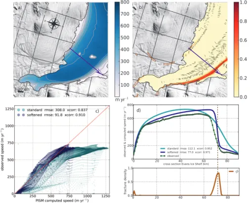
5.2.2 Evans Inlet in Ronne Ice Shelf
The ice stream of the Evans Glacier enters the second largest Ronne Ice Shelf in the west and turns north. This motion yields an inclined cross profile with a speed of up to
700 m yr−1at the souther margin jumping to almost 100 m yr−1in some minor side inlets
(green profile in Fig. 9 d). Simulations with ordinary stress balance require a small basic 5
flow enhancementESSA=0.1 (light blue in Fig. 9 c,d), in order to reproduce observed
surface velocities in this region. However, neither the inclination of the main flow nor the strong gradient at the southern flank are well represented. Fracture-softening instead exhibits these features and produces a thin fracture band along the rocky margin. From there the fracture zone continues with the main flow and separates the stagnant regions 10
at the sides (right hand side in Fig. 9 d). A relatively high fracture toughness of 140 kPa and a comparably strong healing in the main trunk of the inlet limits the extent of the fracture band and restricts the inflow in the observed range. Observations confirm the presence of elongated fragmental structures close to the margin from where crevasses propagate towards the center line of the inlet.
15
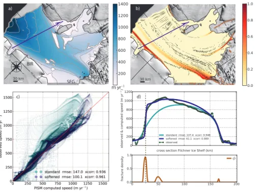
5.2.3 Filchner Ice Shelf
Filchner Ice Shelf is the fastest of the smaller Antarctic ice shelves with speeds up to
1400 m yr−1 close to the front (Fig. 10 a). It shears along Berkner Ice Rise (BIR) at its
western margin and drains into the Weddel Sea in the north. The cross section is lo-cated south of the rifted areas at the north-eastern margin (cf. Fig. 6 b and Fig. 10 c). 20
The maximum speed is shifted from the center line towards the Berkner side with a small buckle at about 70 km distance. This feature likely indicates the presence of a suture zone between the flow unit fed by the Recovery and the flow coming from the Support Force Glacier farther west. The characteristic flow pattern in relation to ob-served surface crevasses was already diagnostically studied by Saheicha et al. (2006), 25
presuming a crevasse band with origin at Recovery Glacier inlet (see overlain
TCD
7, 4501–4544, 2013Fracture-induced softening in ice
dynamics
T. Albrecht and A. Levermann
Title Page
Abstract Introduction
Conclusions References
Tables Figures
◭ ◮
◭ ◮
Back Close
Full Screen / Esc
Printer-friendly Version Interactive Discussion
Discussion
P
a
per
|
Dis
cussion
P
a
per
|
Discussion
P
a
per
|
Discussio
n
P
a
per
|
a symmetric and smooth velocity distribution within the Filchner trough (light blue in Fig. 10 c). A much better representation of elongated structures such as the suture zone representation within the main trunk causing a small kink in the velocity profile is provided by application of the fracture-softening scheme with a relatively high fracture toughness of 130 kPa. For chosen parameters, best agreement with observations is 5
attained with a reduced enhancement for unfractured ice of ESSA=0.2, reproducing
much of the inclination and the steep gradient at the western margin. The straight
in-clined part of the observed profile might be an effect of the rift system downstream,
which is not accounted for in the model.
The characteristic fracture band pattern is also obtained for lower resolution of 2 km or 10
even 5 km (Fig. 11), however much more damped for wider meshes (cf. Fig. 5). Hence
the softening effect is weaker and the typical shape of the across velocity profile is less
pronounced.
5.2.4 Larsen B Region prior to its break-up
The Larsen B Ice Shelf is situated at the north-eastern flank of the Antarctic Peninsula 15
facing the Weddel Sea (Fig. 12). The climatic conditions in this region are considerably
different from those in the more continental ice shelves farther south. Surface melting
during summer can produce melt ponds (Glasser and Scambos, 2008), which initiate a series of processes that can result in such large-scale events as the disintegration of major parts of Larsen B in 2002 within a few weeks (Rack and Rott, 2004). Satel-20
lite observations indicated a heavily crevassed ice-shelf surface prior to the collapse (Fig. 6 c) and model studies confirmed the dynamically active role of those fractured regions (Sandh ¨ager, 2003; Sandh ¨ager et al., 2005; Vieli et al., 2006, 2007; Khazendar et al., 2007; Borstad et al., 2012). Since ordinary model configurations with constant flow enhancement fail to accurately reproduce the characteristic pre-collapse flow pat-25
TCD
7, 4501–4544, 2013Fracture-induced softening in ice
dynamics
T. Albrecht and A. Levermann
Title Page
Abstract Introduction
Conclusions References
Tables Figures
◭ ◮
◭ ◮
Back Close
Full Screen / Esc
Printer-friendly Version Interactive Discussion
Discussion
P
a
per
|
Dis
cussion
P
a
per
|
Discussion
P
a
per
|
Discussio
n
P
a
per
|
of the ice shelf appears plateau-shaped. This can be explained by the partial mechan-ical decoupling from the confining side margins such that a large enhancement factor
ofESSA=10 is needed to reach observed maximum velocity values of up to 560 m yr−
1
along the central front (cf. dashed light blue in Fig. 12 e). Especially along inlets close to the grounding line the computed velocities are far too small (Fig. 12 f).
5
A damage-dependent and hence spatially varying flow enhancement reproduces the observations much better (thick violet in Fig. 12 e,f), since the inferred fracture density identifies the dynamically relevant weak zones and allows for intense located softening
and hence strong flow gradients. This applies even for enhancement factorESSA=1.0
as base level for unfractured ice, which is glaciologically more realistic than values 10
larger than 1. A comparably high value for the fracture rateγ=1.0 and a low value
of the fracture-initiation thresholdσt=60 kPa is needed in order to yield high damage
accumulation close to unit value and hence strong softening in the active regions. Es-pecially within the narrow tributary inlets, densely spaced fractures and hence intense softening occurs, which coincides with detailed observation in theses areas (Glasser 15
and Scambos, 2008, Fig. 2). Surface meltwater draining into existing crevasses and enhancing fracture formation support this parameter choice. On the other hand, for
accumulation rates of more than 1 m yr−1 and possibly refreezing within surface and
bottom crevasses, strong healing γh=2.0 may be plausible. In this parameter
set-ting the healing threshold ˙ǫh=6×10⁻¹⁰s−1becomes a sensitive parameter separating
20
fracture-free regions from those of self-amplified fracture weakening.
5.2.5 Pine Island and Thwaites drainage basin
The Amundson Sea sector with the Pine Island Glacier is one of the key regions in the discussion on sea-level rise. Large portions of the West Antarctic Ice Sheet are drained through this confined fast outlet. Pine Island ice shelf is subjected to enhanced 25
ocean melt and has accelerated by about 50% in the last decade, propagating up-stream (Joughin et al., 2003, 2010; Scott et al., 2009; Warner and Roberts, 2013).
rea-TCD
7, 4501–4544, 2013Fracture-induced softening in ice
dynamics
T. Albrecht and A. Levermann
Title Page
Abstract Introduction
Conclusions References
Tables Figures
◭ ◮
◭ ◮
Back Close
Full Screen / Esc
Printer-friendly Version Interactive Discussion
Discussion
P
a
per
|
Dis
cussion
P
a
per
|
Discussion
P
a
per
|
Discussio
n
P
a
per
|
sonable agreement with observations of surface velocities by Rignot et al. (2011a). However, the fast-flowing portions in the lower Pine Island ice stream and in the ice
shelf are underestimated (peaking up to 4000 m yr−1, see Fig. 13). We applied the
fracture-softening method in a simulation of the Pine Island and Thwaites region in
or-der to demonstrate its effects in a dynamically coupled ice sheet - ice stream - ice shelf
5
system. The procedure identifies fracture zones at the margins of the fast-flowing ice-stream regions leading to an acceleration there. In fact, fractures are visible at the sur-face and may play an interactive role in the complex dynamics of Pine Island Glacier.
In this specific setting, fracture initiation thresholds of σt≤90 kPa can initiate a
run-away feedback, where fracture-induced acceleration and thinning promote grounding 10
line retreat (see sketch in Fig. 13 c). This ungrounding leads to even more acceleration, expansion and shearing, which intensifies in turn fracturing. This phenomenon is worth a separate study but will not be discussed further here.
6 Discussion
Fractured regions in a shear zone can support only limited stress and lose this ability 15
when crossing a specific threshold. Fracture-induced softening has the potential to in-troduce non-linear characteristics into the ice-flow dynamics such as dynamic regime shifts (bifurcation) and hysteresis (irreversibility). This has been investigated for steady-state configurations with respect to successively varied parameters (Fig. 7). A self-amplifying process is then activated and additional fractures intensify the shear, which 20
in turn promotes additional fracturing. Hence, small changes in environmental condi-tions potentially have strong impacts in such systems. A short surface-melting period can trigger a change in fracture threshold and may activate such abrupt shifts between
dynamic regimes. This mechanism is robust and may occur for different settings at
dif-ferent thresholds. Critical effective stresses of 80 kPa as in the demonstrated simplified
25
TCD
7, 4501–4544, 2013Fracture-induced softening in ice
dynamics
T. Albrecht and A. Levermann
Title Page
Abstract Introduction
Conclusions References
Tables Figures
◭ ◮
◭ ◮
Back Close
Full Screen / Esc
Printer-friendly Version Interactive Discussion
Discussion
P
a
per
|
Dis
cussion
P
a
per
|
Discussion
P
a
per
|
Discussio
n
P
a
per
|
histories, temperature regimes, ice properties but also uncertainty in the conversion of measurable strain-rates to stresses (Vaughan, 1993). Hence, stress thresholds are not
constant material parameters and may differ depending on various conditions.
However, independent of this qualitative possibility of non-linear threshold behavior, we find that the influence of fractures on the creep of ice is relevant in a number of 5
situations. This study does not aim at a conclusive investigation of the influence of fracture on the flow field, but is meant to introduce the concept and provide results on the qualitative changes in the flow field when fracture density is accounted for. The critical strengths for the realistic computational setups of Antarctic ice shelves were de-termined such that characteristic observed flow patterns are adequately represented, 10
which provides a rough way of parameter calibration. The so estimated critical values for the large Antarctic ice shelves are located in the lower half of this literature range, i.e., 110 kPa–140 kPa (Fig. 8–10). In contrast a comparably low threshold of 60 kPa was chosen in the smaller Larsen B Ice Shelf situated at the Antarctic Peninsula (Fig. 12). This is counter-intuitive since warmer ice is supposed to support higher stresses be-15
fore failure. However, using higher thresholds in the simulation cannot produce the de-gree of damage within the evolving fracture bands, which is necessary to capture the observed strong shearing for the given setting of enhancement factor and healing
pa-rameters,ESSA,γhand ˙ǫhrespectively. External conditions like melt water draining into
surface crevasses or basal melting intensified within basal crevasses openings provide 20
reasonable explanations for a considerably lower threshold in this region. However, this study is not meant as a parameter-tuning exercise and the inferred parameters should
be considered with caution. Generally, for increasing basic enhancement factorESSA,
stresses are intensified throughout the ice shelf domain and thresholds are more likely hit at stress maxima. Related ice-shelf thinning is not further discussed here. The signal 25
simu-TCD
7, 4501–4544, 2013Fracture-induced softening in ice
dynamics
T. Albrecht and A. Levermann
Title Page
Abstract Introduction
Conclusions References
Tables Figures
◭ ◮
◭ ◮
Back Close
Full Screen / Esc
Printer-friendly Version Interactive Discussion
Discussion
P
a
per
|
Dis
cussion
P
a
per
|
Discussion
P
a
per
|
Discussio
n
P
a
per
|
lations of ice shelves. Since tensile crevassing occurs predominantly in pre-fractured ice, we do not distinguish between the particular failure behavior and assume a smooth transition of ductile to brittle fracturing. In the present formulation we account for
hor-izontal interactions simply parameterized by a factor (1−φ) in Eq. (2), bounding the
evolving fracture density. However, this integrated view neglects the vertical extent 5
and possibly non-linear interactions of basal and surface crevasses (McGrath et al., 2012b,a; Luckman et al., 2012; Vaughan et al., 2012). In fact, the vertical dimension of fracturing is relevant in understanding fracture interaction and calving and needs to be specified in an expanded formulation for the fracture density. To give an example, tensile crevasse formation at the ice-shelf bottom triggered by vertical bending at the 10
grounding line (Logan et al., 2013) cannot be captured by shallow approximation
mod-els. Contribution of such processes may be considered as boundary conditions,φ0, in
future studies. Considering the involved vertical bending stresses, tidal flexure seem to play a secondary role.
The presented method locates the areas that are most susceptible to fracture forma-15
tion. With origin in these spots, elongated damage bands often reach far downstream towards the front. Viscosity is reduced along these confined fractured zones assum-ing a linear relationship, comprisassum-ing all relevant softenassum-ing processes (includassum-ing micro-scale dynamic recrystallization or damage-induced anisotropy). This procedure mimics a partial mechanical decoupling of the so-separated regions and reproduces a couple 20
of observed flow characteristics: Fast-flowing units of the ice shelf pass by stagnant ice shelf regions in minor side bays (Fig. 9 and 12) or get sutured together with
neighbor-ing flow units of different speed. This can be identified by jumps or kinks in ice-speed
cross-section (Figs. 8 and 10). Ice-stream inlets shearing along the rocky fjord walls accelerate when the main flow gets partly detached from the sticky margins (Figs. 9 25
and 13). Similar effects are observed within small ice shelves shearing along islands
or ice rises. Along these fractured zones of weakness transversal stresses cannot be
transferred effectively leading to increased speed and less buttressing. Observations
TCD
7, 4501–4544, 2013Fracture-induced softening in ice
dynamics
T. Albrecht and A. Levermann
Title Page
Abstract Introduction
Conclusions References
Tables Figures
◭ ◮
◭ ◮
Back Close
Full Screen / Esc
Printer-friendly Version Interactive Discussion
Discussion
P
a
per
|
Dis
cussion
P
a
per
|
Discussion
P
a
per
|
Discussio
n
P
a
per
|
active zones such as highly fragmented shear zones are not necessarily visible for cur-rently available resolutions (Fig. 6) and, vise versa, certain observable surface features may be irrelevant for the dynamics. Furthermore, the active areas often act as pre-cursor for visible crevasse and rift formations (Bassis et al., 2008; Hulbe et al., 2010), which can be identified easily as transversal expressions often reaching far into un-5
damaged areas. Huge rift systems can be completely deactivated, i.e. healed, when filled with m ´elange. These complex implications questions the robustness of validat-ing the computed fracture density against observed surface-fracture features. Inverse control methods provide an intelligent validation tool by inferring such active zones for a given snapshot of observed surface velocities (Khazendar et al., 2007; Borstad 10
et al., 2012, 2013; Habermann et al., 2012, available in PISM). Controlling factors like ice fabric, marine ice or meltwater are implicitly included. Nevertheless time evolution is needed to understand causalities. Especially regarding the coupling of the evolv-ing fracture density in an enhanced calvevolv-ing scheme. A natural link exists already in the given framework between fracture-induced modification of internal stresses and 15
the strain-rate-based calving scheme (Levermann et al., 2012), but this is beyond the scope of this study.
7 Conclusions
We developed a phenomenological scalar fracture-density evolution model coupled to viscous-creep deformation in shallow approximation. This formulation, based on first-20
order assumptions, captures the gross interactions of fracture processes and flow dy-namics. The aim of this study is to represent characteristic ice-flow behavior at the macroscale and to roughly constrain involved parameters using satellite data. Its im-plementation into a conventional ice sheet and ice shelf model is straight forward. An enhanced transport scheme improves the representation of the fracture-density advec-25
TCD
7, 4501–4544, 2013Fracture-induced softening in ice
dynamics
T. Albrecht and A. Levermann
Title Page
Abstract Introduction
Conclusions References
Tables Figures
◭ ◮
◭ ◮
Back Close
Full Screen / Esc
Printer-friendly Version Interactive Discussion
Discussion
P
a
per
|
Dis
cussion
P
a
per
|
Discussion
P
a
per
|
Discussio
n
P
a
per
|
fracture-density approach provides a spatial and temporal link between small-scale fracture initiation and post-formation processes occurring on the large scale and even-tually located elsewhere. Rift propagation and calving would be examples of such phe-nomena. Hence, the structural integrity and stability of key regions, buttressing the ice flow, can be evaluated in a more realistic manner and potential contributions to global 5
sea level can be assessed with more confidence.
Acknowledgements. We thank Ed Bueler, Constantine Khroulev and David Maxwell
(Univer-sity of Alaska, USA) for a great collaboration and technical assistance with the Parallel Ice Sheet Model (PISM), development of which is supported by NASA grants NNX09AJ38C, NNX13AM16G, and NNX13AK27G. We are grateful for stimulating discussions with Guillaume 10
Jouvet. We also thank Matthias Mengel for preprocessing various datasets. Ralph Timmer-mann kindly provided FESOM sub-shelf melting data and Neil Glasser detailed observational surface feature maps of the Larsen Ice Shelves. T. A. was funded by the German National Merit Foundation (Studienstiftung des deutschen Volkes).
References
15
Albrecht, T. and Levermann, A.: Fracture field for large-scale ice dynamics, J. Glaciol, 58, 2012. 4504, 4505, 4506, 4512
Bamber, J. L. and Aspinall, W. P.: An expert judgement assessment of future sea level rise from the ice sheets, Nature Climate Change, 3, 424–427, doi:10.1038/nclimate1778, 2013. 4502 Bamber, J. L., Riva, R. E. M., Vermeersen, B. L. A., and LeBrocq, A. M.: Reassessment 20
of the Potential Sea-Level Rise from a Collapse of the West Antarctic Ice Sheet, Sci-ence, 324, 901–903, doi:10.1126/science.1169335, http://www.sciencemag.org/cgi/doi/10. 1126/science.1169335, 2009. 4503
Bassis, J. N. and Jacobs, S.: Diverse calving patterns linked to glacier geometry, Nat. Geosci., advance online publication, doi:10.1038/ngeo1887, 2013. 4504
25
TCD
7, 4501–4544, 2013Fracture-induced softening in ice
dynamics
T. Albrecht and A. Levermann
Title Page
Abstract Introduction
Conclusions References
Tables Figures
◭ ◮
◭ ◮
Back Close
Full Screen / Esc
Printer-friendly Version Interactive Discussion
Discussion
P
a
per
|
Dis
cussion
P
a
per
|
Discussion
P
a
per
|
Discussio
n
P
a
per
|
Benn, D. I., Warren, C. R., and Mottram, R. H.: Calving processes and the dynamics of calving glaciers, Earth-Sci. Rev., 82, 143–179, 2007. 4504
Borstad, C. P., Khazendar, A., Larour, E., Morlighem, M., Rignot, E., Schodlok, M. P., and Seroussi, H.: A damage mechanics assessment of the Larsen B ice shelf prior to collapse: Toward a physically-based calving law, Geophys. Res. Lett., 39, L18502, http://www.agu.org/ 5
pubs/crossref/2012/2012GL053317.shtml, 2012. 4503, 4506, 4518, 4523
Borstad, C. P., Rignot, E., Mouginot, J., and Schodlok, M. P.: Creep deformation and buttress-ing capacity of damaged ice shelves: theory and application to Larsen C ice shelf, The Cryosphere Discussions, 7, 3567–3610, doi:10.5194/tcd-7-3567-2013, 2013. 4503, 4507, 4523
10
Bueler, E. and Brown, J.: Shallow shelf approximation as a “sliding law” in a thermomechanically coupled ice sheet model, J. Geophys. Res., 114, F03008, 2009. 4504
Cazenave, A. and Llovel, W.: Contemporary sea level rise, Annu. Rev. Mar. Sci., 2, 145– 173, http://www.annualreviews.org/doi/abs/10.1146/annurev-marine-120308-081105, 2010. 4502
15
Church, J., White, N., Konikow, L., Domingues, C., Cogley, J., Rignot, E., Gregory, J., van den Broeke, M., Monaghan, A., and Velicogna, I.: Revisiting the Earth’s sea-level and energy budgets from 1961 to 2008, Geophys. Res. Lett., 38, L18601, 2011. 4502
Cook, A. J. and Vaughan, D. G.: Overview of areal changes of the ice shelves on the Antarc-tic Peninsula over the past 50 years, The Cryosphere, 4, 77–98, doi:10.5194/tc-4-77-2010, 20
2010. 4504
Duddu, R. and Waisman, H.: A temperature dependent creep damage model for polycrystalline ice, Mechanic. Material., 46, 23–41, doi:10.1016/j.mechmat.2011.11.007, 2012a. 4506, 4507 Duddu, R. and Waisman, H.: A nonlocal continuum damage mechanics approach to simulation of creep fracture in ice sheets, Comput. Mechanic., 51, 961–974, doi:10.1007/s00466-012-25
0778-7, 2012b. 4506
Dupont, T. K. and Alley, R. B.: Assessment of the importance of shelf buttressing to ice-sheet flow, Geophys. Res. Lett., 32, L04503, 2005. 4503
Erdogan, F. and Sih, G.: On the crack extension in plates under plane loading and transverse shear, J. Basic Eng., 85, 519–527, 1963. 4509
30
TCD
7, 4501–4544, 2013Fracture-induced softening in ice
dynamics
T. Albrecht and A. Levermann
Title Page
Abstract Introduction
Conclusions References
Tables Figures
◭ ◮
◭ ◮
Back Close
Full Screen / Esc
Printer-friendly Version Interactive Discussion
Discussion
P
a
per
|
Dis
cussion
P
a
per
|
Discussion
P
a
per
|
Discussio
n
P
a
per
|
Gim, Y., Gogineni, P., Griggs, J. A., Hindmarsh, R. C. A., Holmlund, P., Holt, J. W., Jacobel, R. W., Jenkins, A., Jokat, W., Jordan, T., King, E. C., Kohler, J., Krabill, W., Riger-Kusk, M., Langley, K. A., Leitchenkov, G., Leuschen, C., Luyendyk, B. P., Matsuoka, K., Mouginot, J., Nitsche, F. O., Nogi, Y., Nost, O. A., Popov, S. V., Rignot, E., Rippin, D. M., Rivera, A., Roberts, J., Ross, N., Siegert, M. J., Smith, A. M., Steinhage, D., Studinger, M., Sun, B., 5
Tinto, B. K., Welch, B. C., Wilson, D., Young, D. A., Xiangbin, C., and Zirizzotti, A.: Bedmap2: improved ice bed, surface and thickness datasets for Antarctica, The Cryosphere, 7, 375– 393, doi:10.5194/tc-7-375-2013, 2013. 4513
Glasser, N. F. and Scambos, T. A.: A structural glaciological analysis of the 2002 Larsen B ice-shelf collapse, J. Glaciol., 54, 3–16, 2008. 4504, 4512, 4518, 4519
10
Glasser, N. F., Kulessa, B., Luckman, A., Jansen, D., King, E. C., Sammonds, P. R., Scambos, T. A., and Jezek, K. C.: Surface structure and stability of the Larsen C ice shelf, Antarctic Peninsula, J. Glaciol., 55, 400–410, 2009. 4512
Gregory, J. M., White, N. J., Church, J. A., Bierkens, M. F. P., Box, J. E., van den Broeke, M. R., Cogley, J. G., Fettweis, X., Hanna, E., Huybrechts, P., Konikow, L. F., Leclercq, P. W., 15
Marzeion, B., Oerlemans, J., Tamisiea, M. E., Wada, Y., Wake, L. M., and van de Wal, R. S.: Twentieth-century global-mean sea-level rise: is the whole greater than the sum of the parts?, J. Climate, p. 121203145300007, doi:10.1175/JCLI-D-12-00319.1, 2012. 4502
Gudmundsson, G. H.: Ice-shelf buttressing and the stability of marine ice sheets, The Cryosphere, 7, 647–655, doi:10.5194/tc-7-647-2013, 2013. 4503
20
Habermann, M., Maxwell, D., and Truffer, M.: Reconstruction of basal properties in ice sheets using iterative inverse methods, J. Glaciol., 58, 795–807, doi:10.3189/2012JoG11J168, 2012. 4523
Hanna, E., Navarro, F. J., Pattyn, F., Domingues, C. M., Fettweis, X., Ivins, E. R., Nicholls, R. J., Ritz, C., Smith, B., Tulaczyk, S., Whitehouse, P. L., and Zwally, H. J.: Ice-sheet mass balance 25
and climate change, Nature, 498, 51–59, doi:10.1038/nature12238, 2013. 4502
Hulbe, C. L., LeDoux, C., and Cruikshank, K.: Propagation of long fractures in the Ronne Ice Shelf, Antarctica, investigated using a numerical model of fracture propagation, J. Glaciol., 56, 459–472, 2010. 4503, 4509, 4523
Humbert, A.: Numerical simulations of the ice flow dynamics of Fimbulisen, in: FRISP Report, 30