Electrodes
Diogo Miguel Esperança Garcia,
†,‡Ana Sofia Taborda Martins Pereira,
†António Carranca Almeida,
†Urbez Santana Roma,
‡Alejandra Ben Aissa Soler,
‡Paul D. Lacharmoise,
‡Isabel Maria das Mercês Ferreira,
*
,†and Cláudia Custódio Delgado Simão
‡†CENIMAT/I3N, Departamento de Ciência dos Materiais, Faculdade de Ciências e Tecnologia, Universidade Nova de Lisboa, 2829-516 Caparica, Portugal
‡Eurecat, Centre Tecnológic de Catalunya, 08290 Barcelona, Spain
*
S Supporting InformationABSTRACT: Large-area paper batteries have been explored in this paper, correlating electrode materials and screen printing
with the electrochemical performances. The use of office paper embedded in salt solution with two electrodes performed by an easy and large-scale application technique opens doors to a new concept of energy storage. The proposed device is Li-free and uses zinc and silver powder-based screen printable pastes to deposit the electrodes. Cyclic voltammetry and charge−discharge curves reveal the performance of the produced devices using NaCl and KOH solutions in different concentrations. The simulation of electrochemical impedance spectroscopy measurements gave clue of a similar working mechanism to conventional Li-ion batteries. After charging, a single paper battery achieves 1.83 V with 60 mA/cm2and 90.6% charge−discharge efficiency. As a proof of concept, a small paper battery and a set integrated in series and parallel were used to power a commercial red light-emitting diode.
■
INTRODUCTIONOver the years, printing technologies have emerged as a possibility to perform flexible electronics, meaning that the devices produced are bendable, with conformal shape, lightweight, elastic, nonbreakable, and roll-to-roll manufac-tured over small or large area.1−3
Flexible electronics have been applied in several wearable devices, flexible energy storage and conversion, sensors, displays, organic light-emitting diodes (LEDs), antennas, and transistors.4−6 Expensive and time-consuming processes such as spin coating, sputtering, thermal evaporation, and other clean room techniques have been used to deposit the conductive electrodes to those applications. However, when using substrates such as paper, plastics or textiles and printing techniques such as ink-jet printing, screen printing, flexo-graphic printing, and gravure printing are more suitable for rugged and flexible substrates and in the use of roll-to-roll machinery, which enables high-speed and low-cost fabrication processes offlexible devices.7−10
The search for new processes and scalability of batteries using low-cost procedures and low environmental impact materials leads researchers tofind some new solutions. Among those, paper batteries have become a fulfilled challenge.7The use of paper as a substrate or as the active layer in electronic devices such as transistors, disposal diagnostic devices, and electrical energy storage devices has already been proved.8,11−14 The paper is formed by cellulose-based fiber and has a high superficial area, ability to wick fluids via capillary action, and strong adhesion to a variety of materials.15Two of the most frequently used printing techniques for depositing a layer of material on top of the paper surface are ink-jet and screen printing, but specific inks with appropriate viscosity and surface tension are required.7,16−19
Received: May 27, 2019
Accepted: August 2, 2019
Published: September 30, 2019
Downloaded via 94.63.138.126 on September 30, 2020 at 16:39:50 (UTC).
Most of the state-of-the-art printed batteries are either Li-ion batteries or Zn/MnO2. Printed batteries offer many different attributes and features such as their thin thickness, flexibility, low cost and fast fabrication, simple processing, and reproducibility in multiple geometries.19,20 Stacked and coplanar are the most common architectures, while sealing is required to protect them against degradation due to humidity or other environmental agents.
Paper or paper-based composites have already been used as the substrate on printed Li-ion, Zn/MnO2, Al/air, and Zn/air batteries or bacteria-powered batteries for fast diagnostic devices.7,8,19,21,22 Batteries, where commercial paper sheet accumulates the functions of the substrate and a porous separator between the electrodes, were demonstrated. In this case, thermal evaporation deposited the cathode and anode, copper and aluminum, respectively, while air humidity (water vapor) was used as the electrolyte. A self-rechargeable device is able to supply 0.6 V, and each cell was integrated into series to provide enough power to open and close the gate of a field-effect transistor.13,14
In the present work, a paper-based battery with silver- and zinc-printed electrodes is presented. The influence of electrode materials, the electrolyte composition, and screen printing processes for the paper-based batteries fabrication were studied and optimized.
■
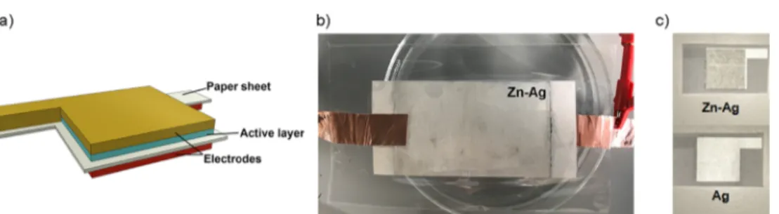
RESULTS AND DISCUSSIONThe Ag/paper/Zn-Ag paper asymmetric structure was achieved by applying the Ag ink in one side of the paper (3.75 mg/cm2) and Zn ink in the opposite side (3.92 mg/
cm2), followed by the application of Ag ink (2.70 mg/cm2), as shown inFigure 1. Ag acts as a current collector while the Zn layer as the intermediate accumulation surface (active layer).
The conductivities of Ag and Zn layers are, respectively, 0.18 and 1.15× 10⁻¹⁰(Ω·cm)−1. SEM cross-sectional imaging was used to measure the thickness of both electrodes, 22± 6 and 37± 5 μm for Ag and Ag-Zn, respectively.
To study the influence of electrolyte, the paper was soaked with different salt solutions followed by an encapsulation step. The maximum open circuit potential (OCP) of a single Ag/ paper/Zn-Ag cell for 1 and 5 M NaCl is 0.85 V while for 1, 5, and 10 M KOH, it is 0.9, 1.11, and 1.14 V respectively.Figure S1 and Table S1 compare the 10th cycle from the cyclic voltammetry (CV) plot for each solution tested at a scanning rate of 80 mV/s. Clearly, the cell with paper soaked in 5 M KOH revealed +60.7 and− 79.7 mA/cm2current densities for
anodic and cathodic peaks, respectively, which were the highest registered. For this reason, 5 M KOH was chosen as the electrolyte for galvanostatic charge and discharge (GCD) tests. Ag/paper/Zn-Ag 5 M KOH device scan rate study (SRS) and CV are presented inFigure 2.
SRS inFigure 2a, accompanied byFigure S2, demonstrated that peak potentials for both anodic and cathodic, are not independent of the scan rate, that is, electrode’s potential at which oxidation and reduction occur is not constant at all scan rates. Moreover, the Randles−Sevčik plot in Figure S2 revealed that, for each scan rate, Ipeak(anodic)≠ Ipeak(cathodic). Both
previous occurrences indicate the presence of quasi-reversible behavior.23−26 Faradaic mechanisms are confirmed by the presence of two anodic peaks and one cathodic peak. These two anodic peaks appear at +2 V (60.71 mA/cm2) and +2.3 V (52.81 mA/cm2), and the cathodic peak appears at +1.2 V
(−79.7 mA/cm2). Secondary zinc/silver oxide batteries had
been described in the literature, and their electrochemical cell reactions (in aqueous KOH) are usually as described ineq 1 Figure 1.(a) Electrode/paper/active electrode proposed structure, Ag/paper/Zn-Ag cells. (b) 9× 5.5 cm2 cell produced via bar coating. (c) Screen-printed 2× 2 cm2cell.
Figure 2.(a) Cyclic voltammogram (CV) as a function of scan rate (SRS) for the 10th cycle. (b) CV for different cycle numbers of Ag/paper/Zn-Ag soaked in 5 M KOH. SRS and CV were performed at room temperature, step size of 5 mV, and 20−120 and 80mV/s scan rates, respectively.
+ + F +
AgO Zn H O2 Zn(OH)2 Ag (1)
The discharge of this type of batteries happens in the forward reaction, while the charge process is given by the backward reaction. There are two known reactions happening at the silver electrode during the charge process
+ −→ + + Ag O 2OH 2AgO H O 2e 2 2 (2) + −→ + + 2Ag 2OH Ag O H O 2e 2 2 (3)
The anodic peaks detected in CV measurements for the Ag/ Paper/Zn-Ag device of this work can be attributed to the oxidations, that is, the loss of electrons, described ineqs 2and
3. Equation 3 describes the first anodic peak, and eq 3
describes the anodic peak at higher potential.27 At the same time, zinc electrode is reduced followingeq 4
+ → + −
Zn(OH)2 2e Zn 2OH (4)
Since these three mechanisms are reversible, discharge process will follow the reverse direction of reactions. In Figure 2b, it can be observed the reactions are stable for a scan rate of 80 mV/s. Little differences between curves from 3rd to 20th scans can be also appreciated.
XPS measurements were performed on Ag and Zn-Ag electrode surface as printed and after electrochemical studies with 1 M NaCl solution. In the latter, apart from the top surface analysis, the electrodes were also peeled with scotch tape to analyze the inner interface. The obtained general XPS
spectra are displayed inFigure 3. The complete XPS spectra peaks can be consulted inTable S2(Supporting Information).
Figure 3a (Ag electrode) shows that before the electro-chemistry studies, only C 1s, Ag 3d, O 1s, and Ag 3p orbitals were detected. On the contrary, after the electrochemistry, Na 2s, Zn 3p, Zn 3s, Cl 2p, Zn 2p, and Na 1s appeared in both top surface and the surface of peeled samples, which was expected due to the possible presence of Zn species moving through the liquid electrolyte that also soaked the electrodes. The spectra inFigure 3b reveal the presence of Ag 3d, Ag 3p, O 1s, and C 1s on the electrode’s surface before electrochemistry as XPS is only a superficial technique; peaks related to Zn are not expected. After the electrochemical studies, Zn 3d, 3p, 3s, and 2p peaks appear on the electrode’s top surface while Ag 3p peaks disappear and Ag 3d suffers a great loss in terms of intensity. This can be explained by the material loss in the Ag layer due to electrochemical irreversibility, decreasing its thickness or by the deposition of Zn compounds, which moves through the electrolyte on the Ag layer. The migration of material in zinc electrodes followed by shape change has been reported previously.27 Moreover, Cl 2p and Ni LMM peaks appeared after the electrochemistry. Thefirst is related to the electrolyte, while the latter can be associated with the LAIRD tape used as the device’s external output since it is a Ni−Cu conductive alloy. When analyzing the electrode’s inner surface attached to the scotch tape, F 1s and F KLL peaks
Figure 3.XPS general spectra for the Ag/paper/Zn-Ag cell as printed and after electrochemical studies with 1 M NaCl: (a) Ag electrode and (b) Zn-Ag electrode.
appeared, and there is no sign of Ag. Fluorine is part of Zn paste’s composition.
Cross-sectional areas of Ag/paper/Zn-Ag samples as printed and after the electrochemical studies with 5 M KOH were observed by SEM, and the images are displayed inFigure 4. In the image of the as-printed sample, the Ag layer is well identified as the brighter gray color present on top and bottom of the image, and Zn shows a darker gray color and it is formed byflake-like sheets. The black color of the paper sheet can be also observed. After the electrochemical studies (Figure 4, after electrochemistry), the Zn layer lost its flake-like structures, turning into smaller rounded flakes while the silver layer is reduced. However, the CV measurements reveal that devices are working even though these morphology changes occur.
Figure S3better illustrates the Ag and Zn-Ag electrodes top view SEM images as printed and after 20 cycles at 80 mV/s CV measurements. The EDS obtained in each region are shown in
Table S4of the Supporting Information. The obtained values agree with XPS results.
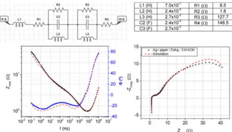
EIS measurements were performed on Ag/paper/Zn-Ag with the 5 M KOH device. The obtained Nyquist plot shape in
Figure 5 is similar to the ones obtained for Li-ion batteries.28−30As in Li-ion batteries, in the Ag/paper/Zn-Ag 5 M KOH device, the EIS response shows a straight line with a positive slope and a small curvature that intersects the abscissa axis in the high-frequency region, revealing the battery’s stray inductance due to the screen-printing architecture and ohmic losses. The charge transfer reactions at electrode surfaces are reflected in real impedance as anode and cathode activation losses by the presence of the depressed semicircles in the middle frequency region, with some inductive effect. This device has no mass transport losses. The complete equivalent electrical circuit can be observed in Figure 5, and the fitting parameters are displayed in the table therein.
Ag/paper/Zn-Ag cells soaked with 5 M KOH and encapsulated were submitted to GCD tests. Right after the encapsulation, OCP was measured. Then, a first discharge, limited to 0.3 V minimum voltage, was imposed by applying −50 μA and −1 mA. Discharge plots are presented inFigure 6a. For 50 μA constant current applied, the discharge took more than 8 h, while for−1 mA, the discharge was completed in 9 min. Cyclic GCD was performed, and +1.0 and−1.0 mA
Figure 5.Nyquist plot obtained for the Ag/paper/Zn-Ag 5 M KOH device performed between 1 MHz and 0.1 Hz at room temperature. The dashed line corresponds to thefitting to an inductor (L1) connected in series with a resistor (R1) and with two parallel connected cathode and anode elements (R2− C2 − L2 and R3 − C3 − L3) and another resistor (R4). Equivalent electrical circuit fitted from both Nyquist and Bode plots as displayed in the circuit above.
Figure 6.(a) First discharges of GCD tests on Ag/paper/Zn-Ag cells with 5 M KOH. Constant current discharges with−50 μA and −1 mA applied. (b) Cyclic GCD on the Ag/paper/Zn-Ag 5 M KOH device. First and second charging stages lasted 15 min, while the rest took 20 min. Currents +1 mA and−1 mA were applied for charging and discharging the device, respectively, at room temperature.
electrode, confirming the oxidation reaction mentioned previously and presented in CV. This voltage value matches the beginning of the first oxidation peak on the CV plot in
Figure 2b, that is, Ag oxidation to Ag2O. Discharge plateaus were expected since two voltage plateaus are described in the literature for zinc/silver oxide batteries, which are related to the two-step reduction of AgO to Ag. However, only one plateau is observed, which, in fact, is in accordance with the charge process performed. This voltage plateau, above 1.5 V on every cycle, is therefore attributed to the monovalent oxide reduction. First and second discharges lasted 14 min (average) for 15 min of charging, while third, fourth, andfifth lasted 18 min (average) for 20 min of charging. Other GCD tests were performed to confirm that the referred reaction was a key step to convert and store electrical energy in the device so that the discharge was faster when the reaction did not happen. After the end of the last discharge, OCP was measured, showing self-recuperation in terms of voltage.
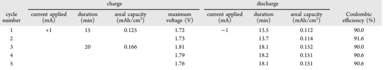
To have a first impression on the cycling stability of the battery, the areal capacity on charge and discharge steps was plotted against the cycling number (Figure 7). The difference
cycle. An average of 90.6% CE for five cycles was
determined. On an ideal scenario, this value would be 100%; since this is not the case, the device might be facing undesired irreversible side reactions during its performance.
Table 1summarizes the performed GCD studies.
To demonstrate the viability of the Ag/paper/Zn-Ag 5 M KOH device as a viable energy storage device, it was tested to power a commercial red LED (20 mW, 660 nm). A single cell and a set of three series of parallel-connected five cells were tested. The devices were totally discharged atfirst, recharged, and then connected to the LED. Images of a single cell and series/parallel connection are shown in Figure 8. The single cell was connected to an LED after charging (+1 mA for 20 min), and one frame from the video recorded when the device was connected to the LED is shown inFigure 8. A single cell was capable of powering a red LED, even though the LED brightness was low, for 4−6 h. When the LED got to its off state, the device was recharged, again with +1 mA, but this time, it lasted for 30 min. The charging process ended, and the device was, again, connected to the LED and able to power it once again with similar brightness, this time only for 20−40 min.
The same procedure was applied to the set of devices connected as mentioned before. The charge process was performed by applying +5 mA during 20 min followed by its connection to continuously power the LED; this time, the light emission was observed only for 2−3 min (approximately), but the emitted light was much brighter, as shown in Figure 8. However, the LED emission was a blinking light, which might be caused by current leaks between cells due to bad contact connections of LAIRD tape.
■
CONCLUSIONSAg/paper/Zn-Ag (2× 2 cm2) cells were screen-printed, and among other concentrations tested, the 5 M KOH electrolyte solution led to a higher current density with an average OCP of 1.11 V and quasi-reversible behavior with anodic peaks at +1.96 V (60.71 mA/cm2) and +2.30 V (52.81 mA/cm2) and a cathodic peak at +1.21 V (−79.7 mA/cm2). CV and GCD
studies demonstrated the electrochemical performance of the developed device, which is comparable to that of zinc/silver oxide secondary batteries. SEM-EDS and XPS measurements obtained after electrochemistry studies revealed that Zn is
Figure 7.Cycling stability studies considering the areal capacity and Coulombic efficiency versus cycle number.
Table 1. Summary of GCD Studies on Ag/Paper/Zn-Ag 5 M KOH Device
charge discharge cycle number current applied (mA) duration (min) areal capacity
(mAh/cm2) voltage (V)maximum current applied(mA) duration(min) areal capacity(mAh/cm2) efficiency (%)Coulombic
1 +1 15 0.125 1.72 −1 13.5 0.112 90.0
2 1.73 13.7 0.114 91.6
3 20 0.166 1.81 18.1 0.152 90.0
4 1.79 18.2 0.151 90.6
deposited on the electrode surface. The oxidation of Zn was observed through SEM-EDS analysis where the typical nanoflower and nanoneedle structures of ZnO are observed. This was also confirmed by the increase in the atomic percentage of oxygen at the electrode surface. SEM cross-sectional images confirmed that after electrochemical pro-cesses, the initialflake-like shape of Zn is no longer observed and the Ag electrode layer was consumed after faradaic mechanisms happened. EIS Nyquist plot revealed a conven-tional Li-ion batteries behavior, and GCD showed Ag/paper/ Zn-Ag 5 M KOH device as a secondary battery. A 90.6% CE was measured for a single cell. A potential increase measured without any current applied revealed a self-charge device.
A red LED was powered by a single Ag/paper/Zn-Ag 5 M KOH cell for 4−6 h after 20 min of +1 mA application. Five cells connected in parallel were prepared, and then three of these sets were connected in series to supply power in the same red LED. Although high brightness is observed, the duration was much less (2−3 min). This was attributed to ohmic losses in the electrical parallel and series connections, which will be improved in further works.
■
EXPERIMENTAL SECTIONThe studied structure consists of a stack architecture where a commercial paper sheet is both the substrate and the separator of the device. The electrodes were printed on opposite sides of the substrate in a 2 × 2 cm2 (electrodes overlapping area) squared geometry (Figure 9).
The electrodes were printed on office paper with a medium-sized pneumaticflat screen printer from ATMA (model AT-60FA). Zinc inks were applied on the surface of the paper by bar coating (performed with K Control Coater from RK Print Coat Instruments; bar, 3; velocity, 3), previously to the
printing stage. Commercial silver and carbon inks were screen-printed according to steps 1 to 3 of Figure 10. All heat treatments were performed on a UN160 lab oven from Memmert.
Devices were encapsulated following the procedure inFigure 10, from step 4 to 7. External contacts were prepared with two different conductive adhesive tapes of Cu and LAIRD. These were laser cut in a 0.5× 2.9 cm2rectangular geometry. Two different types of encapsulation were tested with polyethylene sealing films (Titer-Tops) and Fellowes 80 μm laminating pouch, and both were previously cut in 6× 6 cm2squares. To
protect the device from any kind of glue and residues, two 3× 3 cm2polyethylene terephthalate (PET) squares were placed
between the paper device and the outer encapsulationfilm, one for each side. The lamination was performed, immediately after soaking the device in the electrolyte solution, on a Fellowes Venus A3 laminating machine using room temperature and the 80μm temperature settings already installed in the equipment for the polyethylene sealing films and Fellowes laminating pouches, respectively.
Figure 8.Single cell and series/parallel cell connection devices. Red commercial LED powered by each of Ag/paper/Zn-Ag 5 M KOH device.
Figure 9.Schematic of the geometry for the paper battery.
Figure 10. Device fabrication representation. The printing and encapsulation processes are presented on steps 1−3 and 4−7, respectively. (1) A4 paper sheet heat treatment at 130°C (15 min). (2) Anode printing and subsequentfilm thermal curing at 130 °C (15 min). (3) Cathode is printed on the opposite side of the sheet and then thermally cured at 130°C (15 min). (4) Cells are individualized and cut in the proposed device geometry. (5) Two conductive tape pieces are stick to the electrodes. (6) Device is immersed in the electrolyte. (7) Encapsulated device.
immediately after the device encapsulation. All measurements were performed at room temperature.
■
ASSOCIATED CONTENT*
S Supporting InformationThe Supporting Information is available free of charge on the
ACS Publications website at DOI: 10.1021/acsome-ga.9b01545.
CV measurements with different electrolytes; SRS and XPS studies; SEM electrode’s top view images; SEM-EDS analysis (PDF)
■
AUTHOR INFORMATIONCorresponding Author
*E-mail:[email protected].
ORCID
Isabel Maria das Mercês Ferreira:0000-0002-8838-0364
Notes
The authors declare no competingfinancial interest.
■
ACKNOWLEDGMENTSThis work was partially funded by H2020-ICT-2014-1, RIA, TransFlexTeg-645241, ERC-CoG-2014, CapTherPV, 647596, and FEDER funds through the COMPETE 2020 Program and National Funds through FCT - Portuguese Foundation for Science and Technology under the project UID/CTM/50025/ 2019.
■
REFERENCES(1) Han, T. H.; Kim, H.; Kwon, S. J.; Lee, T. W. Graphene-Based Flexible Electronic Devices. Mater. Sci. Eng. R Reports 2017, 118, 1− 43.
(2) Khan, S.; Lorenzelli, L.; Dahiya, R. S. Technologies for Printing Sensors and Electronics over Large Flexible Substrates: A Review. IEEE Sens. J. 2015, 15, 3164−3185.
(3) Cheng, I. C.; Wagner, S. Overview of Flexible Electronics Technology. In Flexible Electronics : Materials and Applications, 1st ed.; Wong, W. S., Salleo, A., Eds.; Springer US, 2009; pp 1−20.
(4) Li, Z.; Liu, H.; Ouyang, C.; Hong Wee, W.; Cui, X.; Jian Lu, T.; Pingguan-Murphy, B.; Li, F.; Xu, F. Recent Advances in Pen-Based Writing Electronics and Their Emerging Applications. Adv. Funct. Mater. 2016, 26, 165−180.
(5) Siegel, A. C.; Phillips, S. T.; Dickey, M. D.; Lu, N.; Suo, Z.; Whitesides, G. M. Foldable Printed Circuit Boards on Paper Substrates. Adv. Funct. Mater. 2010, 20, 28−35.
(6) Li, D.; Lai, W.-Y.; Zhang, Y.-Z.; Huang, W. Printable Transparent Conductive Films for Flexible Electronics. Adv. Mater. 2018, 30, 1704738.
(7) Nguyen, T. H.; Fraiwan, A.; Choi, S. Paper-Based Batteries: A Review. Biosens. Bioelectron. 2014, 54, 640−649.
(8) Cheng, Q.; Song, Z.; Ma, T.; Smith, B. B.; Tang, R.; Yu, H.; Jiang, H.; Chan, C. K. Folding Paper-Based Lithium-Ion Batteries for Higher Areal Energy Densities. Nano Lett. 2013, 13, 4969−4974.
(12) Fraiwan, A.; Mukherjee, S.; Sundermier, S.; Lee, H. S.; Choi, S. A Paper-Based Microbial Fuel Cell: Instant Battery for Disposable Diagnostic Devices. Biosens. Bioelectron. 2013, 49, 410−414.
(13) Ferreira, I.; Bras, B.; Correia, N.; Barquinha, P.; Fortunato, E.; Martins, R. Self-Rechargeable Paper Thin-Film Batteries : Perform-ance and Applications. J. Disp. Technol. 2010, 6, 332−335.
(14) Ferreira, I.; Brás, B.; Martins, J. I.; Correia, N.; Barquinha, P.; Fortunato, E.; Martins, R. Solid-State Paper Batteries for Controlling Paper Transistors. Electrochim. Acta 2011, 56, 1099−1105.
(15) Rolland, J. P.; Mourey, D. A. Paper as a Novel Material Platform for Devices. MRS Bull. 2013, 38, 299−305.
(16) Lee, H.; Choi, S. An Origami Paper-Based Bacteria-Powered Battery with an Air-Cathod. 2015 Transducers - 2015 18th Int. Conf. Solid-State Sensors, Actuators Microsystems, TRANSDUCERS, 2015, 15, 1009−1012.
(17) Hilder, M.; Winther-Jensen, B.; Clark, N. B. Paper-Based, Printed Zinc-Air Battery. J. Power Sources 2009, 194, 1135−1141.
(18) Hu, L.; Choi, J. W.; Yang, Y.; Jeong, S.; La Mantia, F.; Cui, L. F.; Cui, Y. Highly Conductive Paper for Energy-Storage Devices. Proc. Natl. Acad. Sci. U. S. A. 2009, 106, 21490−21494.
(19) Oliveira, J.; Costa, C. M.; Lanceros-Méndez, S. Printed Batteries: An Overview. In Printed Batteries: Materials, Technologies and Applications, 1st ed.; Costa, C. M.; Lanceros-Méndez, S. Eds.; Wiley and Sons Ltd, 2018; pp 1−20.
(20) Huebner, G.; Krebs, M. Printed, Flexible Thin-Film-Batteries and Other Power Storage Devices. In Handbook of Flexible Organic Electronics: Materials, Manufacturing and Applications; Logothetidis, S., Ed. Elsevier Ltd, 2015; pp 429−447.
(21) Fraiwan, A.; Dai, C.; Nguyen, T. H.; Choi, S. A Paper-Based Bacteria-Powered Battery Having High Power Generation. In 9th IEEE International Conference on Nano/Micro Engineered and Molecular Systems, IEEE-NEMS; 2014; pp 394−397.
(22) Madej, E.; Espig, M.; Baumann, R. R.; Schuhmann, W.; La Mantia, F. Optimization of Primary Printed Batteries Based on Zn/ MnO2. J. Power Sources 2014, 261, 356−362.
(23) Aristov, N.; Habekost, A. Cyclic Voltammetry - A Versatile Electrochemical Method Investigating Electron Transfer Processes. World J. Chem. Educ. 2015, 3, 115−119.
(24) Compton, R. G.; Banks, C. E. Cyclic Voltammetry at Macroelectrodes. In Understanding Voltammetry, 3rd ed.; Moses, H.; Brough, Je.; Ying, K. S. Eds.; World Scientific: New Jersey, 2018; pp 113−162.
(25) Monk, P. Analysis by Dynamic Measurement, A: Systems under Diffusion Control. In Fundamentals of Electro-Analytical Chemistry, 1st ed.; Ando, D. J., Ed.; John Wiley & Sons Ltd, 2001; pp 131−192.
(26) Brownson, D. A. C.; Banks, C. E. Interpreting Electrochemistry. In The Handbook of Graphene Electrochemistry, 1st ed.; Brownson, D. A. C.; Banks, C. E.; Eds.; Springer-Verlag London, 2014; pp 23−77. (27) Karpinski, A. P. Silver Oxide Batteries. In Linden’s Handbook of Batteries; 4th ed. Linden, D.; Reddy, T. B. Eds. McGraw-Hill Book Co., 2012; pp 763−792.
(28) Dai, H.; Jiang, B.; Wei, X. Impedance Characterization and Modeling of Lithium-Ion Batteries Considering the Internal Temper-ature Gradient. Energies 2018, 11, 220.
(29) Murbach, M. D.; Schwartz, D. T. Analysis of Li-Ion Battery Electrochemical Impedance Spectroscopy Data: An Easy-to-Imple-ment Approach for Physics-Based Parameter Estimation Using an Open-Source Tool. J. Electrochem. Soc. 2018, 165, A297−A304.
(30) Zhai, N. S.; Li, M. W.; Wang, W. L.; Zhang, D. L.; Xu, D. G. The Application of the EIS in Li-Ion Batteries Measurement. J. Phys. Conf. Ser. 2006, 48, 1157−1161.
(31) Yang, F.; Wang, D.; Zhao, Y.; Tsui, K. L.; Bae, S. J. A Study of the Relationship between Coulombic Efficiency and Capacity Degradation of Commercial Lithium-Ion Batteries. Energy 2018, 145, 486−495.
(32) Autolab Application Note EC08. Basic Overview of the Working Principle of a Potentiostat/Galvanostat (PGSTAT) − Electrochemical Cell Setup. Metrohm Autolab.B.V 2011,pp. 1−3.