Electroactive Properties of Flexible Piezoelectric Composites
Walter Katsumi Sakamotoa,c*; Edmilson de Souzab, Dilip K. Das-Guptac aUniversidade Estadual Paulista, Campus de Ilha Solteira,
Departamento de Física e Química, 15385-000 Ilha Solteira - SP – Brasil
bUniversidade Estadual de Mato Grosso do Sul, Cidade Universitaria, C.P. 351,
79804-970 Dourados – MS, Brasil
cUniversity of Wales, Bangor, School of Informatics, Dean Street, Bangor, Gwynedd,
LL57 1UT, United Kingdom
Received: December 4, 2000; Revised: June 5, 2001
A flexible piezoelectric composite with 0-3 connectivity, made from Lead Zirconate Titanate (PZT) powder and vegetable-based polyurethane (PU), was doped with small amount of semicon-ductor powder. As a result a composite with 0-0-3 connectivity was obtained. The nature of absorption and steady state electrical conduction and the dielectric behaviour have been studied for this ceramic/polymer composite. The dielectric loss processes of the composite were observed to be dominated by those the polymer. Adding a semiconductor phase in the composite the electrical conductivity can be controlled and a continuous electric flux path could be created between the PZT grains. This composite may be poled at low voltage and in shorter time compared with composites without a conductive phase.
Keywords: sensors, piezoelectricity, pyroelectricity, composites, complex permittivity, discharge current
1. Introduction
Ceramic-polymer composites have received consider-able attention from many researchers during the last 30 years1,2,3,4. They were developed to be an alternative material to ferroelectric ceramics and to ferroelectric polymers. Com-bining properties of two single-phase materials (i.e., ceramic and polymer), the composite appear to posses the mechanical strength, flexibility and formability of the polymer together with high electroactive properties of the ceramic.
There are many ways in producing ceramic-polymer composites, but the most commonly studied are the 0-3 connectivity. This concept was established by Newnham and co-workers5to describe the interspatial relationships in a two-phase material. The connectivity has greatest impor-tance in a multiphase material because it controls the me-chanical, electrical and thermal fluxes between the phases. Composites with 0-3 connectivity are obtained by mix-ing the ceramic powder with polymer matrix when the particles are not in contact with each other and the polymer phase is self connected in all dimensions. That is the easiest fabrication procedure of ceramic/polymer composite.
Although ceramic/polymer composites have some ad-vantages compared with ferroelectric ceramics or ferroelec-tric polymers, the poling process deserves special attention because the effective electric field is much less than the applied field as described by Yamada6and by Furukawa7 for 0-3 composites. Such composites will exhibit piezo- and pyroelectricity if they are suitably poled. A detailed inves-tigation is still necessary to develop the composite with optimum properties for good poling conditions.
This work shows some results obtained with flexible piezoelectric composite made from lead zirconate titanate (PZT) and vegetable-based polyurethane (PU) doped with a semiconductor phase. Adding small amounts of carbon powder the electrical conductivity of composite can be controlled and a continuous electric flux path between PZT grain can be established and poling can be carried out at low voltages and in shorter time. Furthermore the permit-tivity and dielectric loss were measured in a wide range of frequency (10-5Hz to 106Hz) using time domain and bridge
techniques.
2. Experimental
2.1. A: Sample
Commercial PZT powder (American Piezo Ceramics APC) and castor oil based polyurethane (GQATP -USP/São Carlos) were used as piezo-ceramic and polymer matrix respectively. A fine-grained carbon (C) was used as semiconductor phase. The PZT powder was mixed with carbon by a vibrator (Mod. DDR-GM9456) for 30 min prior to introducing this mixture in the polyurethane matrix. The composite was placed between two-paraffin paper and pressed at room temperature8. The applied pressure was about 20 MPa and it was possible to obtain samples in the thickness range of 250 µm to 350µm. Aluminium elec-trodes were evaporated onto both sides of the sample after cutting in an appropriated size. The electrodes area were 3.5 x 10⁻⁴m2. Table 1 shows the samples with respective volume percent of carbon used in this work.
Materials Research, Vol. 4, No. 3, 201-204, 2001. © 2001
*e-mail: [email protected]
2.2. B: Measurement
The Pennebaker Mod. 8000 Piezo d33Tester (APC) was
used for the measurement of d33piezo coefficient in the
thickness direction. A high voltage supply (TREK Mod. 610C) was used for poling the sample that was conditioned in a temperature- controlled chamber. In the charging and discharging procedure the currents were monitored with an electrometer Keithley model 617.
The dielectric data were taken using a General Radio Bridge model 1621 and the time domain technique and subsequent Hamon approximation9for the low-frequency range.
3. Results and Discussion
Figure 1 shows the typical nature of field dependence of charging Ic(t) and discharging Id(t) currents at room
temperature, for fields 1 x 10⁵ V/m to 1 x 10⁶ V/m in PZT/C/PU composite with 59/1/40 vol. % composition. For E = 1 x 10⁵V/m the magnitudes of charge and discharge transients were mirror images of each other. For E = 5 x 10⁵ V/m the mirror image nature was observed at short time and for time above 300 s the charging and discharge transients departed from mirror image nature. At E = 1 x 10⁶V/m there is no mirror image and the charging transients suggest the beginning of the space charge effect.
The discharge current follows the well-known expres-sion10,
Id= A(T)t-n (1)
where A(T) is a temperature dependent factor, t is the time after removal of the externally applied electric field and n≈ 0.6 for this sample showing that space charge polarisation is not a dominant effect11. Similar result was reported by Das-Gupta and Abdullah12who found that the quasi-steady state conduction current in PZT5/VDF-TrFE 50/50 vol.% composite is of ionic nature. Although the space charge is not a dominant effect it can be present for
electric field over 106V/m. The presence of space charge in the polymer matrix can help in stabilising the polarisation and also can contribute to the piezoelectric activity in porous polymers as shown in recent paper13. The steady state conduction currents were observed at 105s at room temperature and 105V/m electric field.
All samples, shown in Table 1, were poled with 3 MV/m electric field at 100 °C for 1 h. After poling, the d33 coefficient was measured and its nature is shown in
Fig. 2. It may be observed that the highest value of d33
coefficient was observed with PZT/C/PU sample of 59/1/40 vol. % composition. Adding 1.0 vol.% of carbon the d33piezo-coefficient increases by 25% in comparison
with the composite without the semiconductor phase. The values showed are the average of three measurements in three consecutive days. The piezoelectric activity displayed by this composite is due the ceramic phase. Although the space charges are there when an electric field of 106V/m is applied (see figure 1), they just help to stabilise the polari-sation and have no contribution to the piezoelectric coeffi-cient unlike in porous and non-polar polymers. The PU used as matrix, is non-polar but has no piezoelectric activity when poled at this range of electric field.
The highest value of d33 for composite, doped with
1.0 vol.% of semiconductor phase, might be because the carbon particles could be trapped between PZT grains, creating a continuous electric flux path, thus making the
202 Sakamotoet al. Materials Research
Figure 1.Charging and discharging currents in PZT/PU/C with 59/40/1 vol. % at different fields. Room temperature.
Table 1. Composites composition: Volume percent of semiconductor phase, PZT and PU.
Samples PZT (vol. %) PU (vol. %) C (vol. %)
1 60.0 40.0 0.0
2 59.5 40.0 0.5
3 59.0 40.0 1.0
4 58.5 40.0 1.5
5 58.0 40.0 2.0
poling process more efficient. Above 1.0 vol. % of carbon content the piezo- activity is reduced, possibly because the electrical conductivity of the composite has increased so much. SA-Gong et al.14 obtained similar results using epoxy-based polymer as matrix.
Figure 3 shows the piezoelectric coefficient of PZT/C/PU (59/1/40 vol. %) as a function of poling time. It appears that a very short poling time of 5 min was enough to polarise this composite while without carbon the com-posite require almost 1 h to be poled.
Again these results suggest that a presence of carbon particles in the composite film makes easier the poling process by increasing the electrical conductivity of the polymer phase. According to Maxwell-Wagner model15the field acting on the ceramic (PZT) is controlled by the ratio of the electrical conductivity of the polymer to that of the ceramic (σp/σc).
Another parameter considered was the pressure applied to the sample during the preparation and curing of the composite. Figure 4 shows the variation of piezo-activity with the applied pressure. Although the mechanical pres-sure applied to the composite is not directly related with the piezoelectric coefficient, the result suggest that with 20 MPa the compactness of the ceramic grains together with the carbon grains allows a cohesive flux path between the adjacent PZT particles. SA-Gong and co-workers14 found that 50 Mpa was the best pressure to be used for their PZT/C/epoxy composite with 68.5/1.5/30 vol. % composi-tion. Here also the values plotted are the average value of 3 measurements. Figure 5 shows the behaviour of the permittivity and dielectric loss of PZT/PU/C composite with 59/40/1- vol. % poled with 3 MV/m for 5 min at 100 °C. The high frequency data were taken with a General Radio Bridge while the low-frequency data were obtained from the time domain discharge current. The discharge current was measured for 3 h after charging for 27 h. Using the Hamon approximation9, the loss factor ε” could be obtained by,
ε’’= I(t) 2πfC0V
(2)
where I(t) is the magnitude of the transient current at time t, C0 is the geometric capacitance of the electrode area
without the sample, V is the applied voltage for charging the sample and f is the Hamon frequency given by,
f = 0.1
t (3)
The low-frequency permittivity (ε’) was obtained using Kramer-Kronig transformation16given by,
ε’= ε∞+P
∫
∞
ε’’ ω − ω0
dω (4)
whereε∞is the permittivity at infinitely high frequency and P is the Cauchy principal value of the integral.
The experimental data were fitted with Havriliak-Negami equation17,18, with two parameters that has the form,
χ(ω) ∝ 1
[ 1+i( ω ωp
)1−α
]β
(5)
whereχ(ω) is the complex dielectric susceptibility andωp
the frequency where occurs the maximum dielectric loss,α andβare parameters and have no physical significance and 0 <α< 1; 0 <β < 1. The relationship between the permittivity and susceptibility are:
ε’(ω) = ε∞+ε0χ’(ω) (6)
ε’’(ω) = ε0χ’’(ω) (7)
withεo= 8.85 x 10⁻¹²F/m being the permittivity of free
space.
The peak in the dielectric loss around 10 Hz can be attributed to polymer phase since the dielectric spectros-copy of PZT ceramic shows no relaxation peak in this range of frequency19. This peak also was observed in low-density polyethylene (LDPE)20and was attributed to the impurities in the polymer matrix. The quasi dc (QDC) conduction, arising from ionic space charge may be observed at low
Vol. 4, No. 3, 2001 Flexible Piezoelectric Composites 203
Figure 3.Variation of piezoelectric coefficient with the poling time for PZT/PU/C composite with 59/40/1 vol. %.
frequency. This phenomenon is also called low-frequency dispersion (LFD)21.
The values of permittivity and dielectric loss at 1 kHz for PZT/C/PU with 1.0 vol.% of carbon and PZT/PU 60/40 vol.% are: ε’ = 54.0, ε’’ = 2.41 and ε’ = 38.4, ε’’ = 0.82, respectively. The influence of the carbon filler in the dielectric loss is evident.
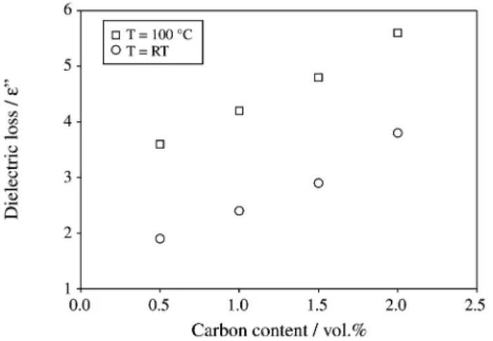
Figure 6 shows the behaviour of dielectric loss of PZT/PU/C composite with 59/40/1 vol.% composition at 1 kHz. It may be observed that the loss factor increases with the increasing of semiconductor phase in the composite, for room temperature and for poling temperature of 100 °C. It is suggested that the enhancement of tanδmay arise from an increasing interfacial polarisation,i.e., Maxwell-Wag-ner effect. Higher values of dielectric loss create difficulty to apply voltage required for poling and the piezoelectric activity decreases as shown in Fig. 2.
4. Conclusions
An addition of a small amount of semiconductor phase in flexible piezoelectric 0-3 composite allows easy poling at relatively low field and in a short time. With 1.0 vol.%
of carbon the piezoelectric longitudinal d33coefficient
be-came 25% higher than that obtained with composite with-out carbon filler, poled at same conditions. The carbon particles located between the PZT grains help to create a continuous electric flux path. By increasing the electrical conductivity of the polymer phase, the applied electric field became more effective on PZT grain.
The applied pressure during the fabrication of the com-posite appears to be an important parameter to obtain samples with surface and grain distribution quality for good piezoelectric coefficient. Morphological analyses should be done for a consistent conclusion about this question.
Although improved poling conditions of such compos-ites are obtained with carbon doping than for the non-doped composite (PZT/PU), the electrical breakdown observed at relative low field (about 6 MV/m), appears to be a disad-vantage. Further studies are in progress to investigate this matter, which might be related with sample preparation.
Acknowledgement
The authors are grateful to Dr. Gilberto O. Chierice for generous supplying of castor oil-based polyurethane. One of the authors (W.K.S.) is grateful to the Fundacao de Amparo a Pesquisa do Estado de Sao Paulo - FAPESP for the pos-doctoral fellowship.
References
1. Furukawa, T.; Fujino, K.; Fukada, E.Jpn. J. Appl. Phys., v. 15, p. 2119, 1976.
2. Dias, C.J.; Das-Gupta, D.K.IEEE Trans. Diel. Elect. Ins., v. 3 n. 5, p. 706, 1996.
3. Clegg, W.W.; Jenkins, D.F.L.; Cunningham, M. J.Sensors and Actuators A, v. 58, p. 173, 1997.
4. Sakamoto, W.K.; Shibatta-Kagesawa, S.; Kanda, D.H.F.; Das-Gupta, D.K.J. Mat. Science, v. 33, p. 3325, 1998.
5. Newnham, R.E.; Skinner, D.P.; Cross, L.E.Mat. Res. Bull., v. 13, p. 525, 1978.
6. Yamada, T.; Ueda, T.; Kitayama, T.J. Appl. Phys., v. 53, p. 4328, 1982.
7. Furukawa, T.; Ishida, K.; Fukada, E.J. Appl. Phys., v. 50, p. 4904, 1979.
8. Souza, E. Master Thesis - UNESP/Ilha Solteira, SP, August, 2000. 9. Hamon, B.V.Proc. IEE, v. 99, p. 151, 1952.
10. Das-Gupta, D.K.IEEE Trans. Dielect. Elect. Ins., v. 4, n. 2, p. 149, 1997.
11. Abdullah, M.J.; Das-Gupta, D.K.IEEE Trans. Elect. Ins., v. 25, n. 3, p. 605, 1990.
12. Das-Gupta, D.K.; Abdullah, M.J.J. Mat. Sci. Letters, v. 7, p. 167, 1988.
13. Gerhard-Multhaup, R.; Künstler, W.; Görne, T.; Pucher, A.; Wein-hold, T.; Seiß, M.; Xia, Z.; Wedel, A.; Danz, R.IEEE Trans. Dielect. Elect. Ins., v. 7, v. 4, p. 480, 2000.
14. SA-Gong, G.; Safari, A.; Jang, S.J.; Newnham, R.E.Ferroelectrics Letters, v. 5, p. 131, 1986.
15. Blythe, A.R.;Electrical Properties of Polymer, Cambridge Univer-sity Press, London 1979.
16. Das-Gupta, D.K.; Scarpa, P.C.N. Handbook of Low and High Dielectric Constant Materials and Their Applications, Nalwa, H.S., ed., v. 2, chap. 6, p. 289 1999.
17. Havriliak, S.; Negami, S.J. Polym. Sci. - Polymer Chem., v. 14, p. 99, 1966.
18. Havriliak, S.; Negami, S.Polymer, v. 8, p. 161, 1967.
19. Das-Gupta, D.K.; Abdullah, M.J. Ferroelectrics, v. 87, p. 213, 1988.
20. Das-Gupta, D.K.; Scarpa, P.C.N.IEEE Trans. Elect. Ins., v. 3, p. 366, 1996.
21. Jonscher, A.K.J. Phys. D: Appl. Phys., v. 32, R57, 1999.
FAPESP helped in meeting the publication costs of this article
204 Sakamotoet al. Materials Research
Figure 6.Variation of dielectric loss with the semiconductor phase content in the composite. Frequency = 1 kHz. ( ) T = 100 °C, (O) T = RT.