*e-mail: [email protected]
Department of Mechanical Engineering, Motilal Nehru National Institute of Technology, Allahabad - 211 004, Uttar Pradesh, India.
Sintered Eutectoid P/M Steel Behaviour During Cold Upsetting
A. Rajesh Kannana,*, K.S. Pandeyb, S. Shanmugamc, R. Narayanasamyd
a
Department of Mechanical Engineering, Thiagarajar College of Engineering,
Thiruparankundram, Madurai, 625 015 TamilNadu, India
b
Maulana Azad National Institute of Technology,
Bhopal, 462 007 Madhya Pradesh, India
c
Department of Mechanical Engineering, National Institute of Technology,
Tiruchirappalli, 620 015 TamilNadu, India
d
Department of Production Engineering, National Institute of Technology,
Tiruchirappalli, 620 015 TamilNadu, India
Received: November 20, 2006; Revised: March 3, 2008
Cold upsetting experiments were carried out on sintered Fe-0.8%C steel preforms in order to evaluate the technical relationship that exist between the applied stresses against continuous deformation and densification. Powder preforms of 86% theoretical density and 0.40 of initial aspect ratio were subjected to incremental compressive loading of 0.04 MN under three different friction conditions such as dry, graphite and zinc stearate employed during deformation until fracture appears at free surfaces. Experimental results revealed that the response of applied stresses with induced strain and attained densification exhibits a continuous enhancement but with three different stages. Irrespective of friction conditions the first and third stage shows steep rise, which offers high resistance to deformation, whereas the second stage shows virtually steady state; deformation needed gradual increase in applied stresses but with high rate of densification. Further, preform deformed under without lubricant exhibited maximum strain hardening as well as an enhanced rate of strain hardening through out the deformation in comparison with lubricants employed conditions.
Keywords: friction conditions, applied stresses, deformation and densification, strain hardening
1. Introduction
Powder metallurgy (P/M) technology provides total cost savings, unique properties, reliability, special materials, quality and increased performance. In addition, a special feature that P/M route possess is the tailor made design and thus a complex shape and tight tolerance can be techno – economically produced1. Another key advantage of the P/M process is the ability to produce net shape or near net shape high precision components with a very high material yield compared with other traditional metal working process such as stamping, cast-ing, forging and machining. However, a major goal of conventional P/M industry is to increase the density to match the properties of wrought materials, since the parts produced through conventional powder metallurgy process involves powder blending, compaction and sintering possess low density. Meaning thereby, presence of suf-ficiently large amount of pores act as a site of stress risers and stress concentrators resulting in crack initiation and propagation when it is subjected to mechanical application and hence these parts cannot be employed in structural and heavy duty applications. Thus, to enhance the density of porous materials, it is necessary to eliminate or close the pores by the application of one or more deformation process on a conventional P/M product. To produce full density or net shape product, many secondary operations were evolved2 such as repressing or forging, impregnation, heat-treating, machining, injection mold-ing etc. These products exhibited superior mechanical properties compare to conventional P/M products. It has been reported3,4 that mechanical properties of the final product were the function of the mode through which the maximum densification had been attained leaving aside the other influential factors such as material
character-istics and process parameters. Although, there are many modes for inducing high density in sintered P/M parts, the cold deformation is considered to be a simple and flexible method of producing finished high density parts.
bear-ing cross – sectional area, which in turn increases the applied stress for further deformation. This results in strain hardening behaviour, and it is due to the combined effects of continued deformation and densifica-tion in a porous material. In addidensifica-tion finer particle size is beneficial for inducing strain hardening characteristic in P/M preform as describe elsewhere9. It is reported10 that the strain hardening exponent (n) is always constant for wrought iron, whereas for sintered iron billets it is a function of the initial preform density. Therefore, strain hardening effect due to compressive deformation of porous billets must be taken into account when attempting to estimate the load requirements, design of preforms and dies used under cold upsetting operations.
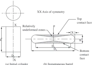
The frictional forces developed between the workpiece and the forming tools are very essential to be considered for any of the metal working processes11,12. During the cold axial upsetting, heterogene-ity in deformation is observed due to the existence of frictional constraints in between the workpiece and top & bottom dies. Just beneath the faces of the flat dies, which are in contact within the workpiece, a conical wedge shaped relatively undeformed material is formed as shown in Figure 1.
But, the remaining materials tend to flow easily towards the near-est free surfaces where the resistance to metal flow is minimum13. Therefore, in cold upsetting, barreling become predominant in ab-sence of the lubrication. However, the detrimental effects of friction can be minimized by the application of proper lubricants. Also, the benefits that can be derived by using lubricants are the reduction in barreling, improvement in surface finish and decrease in wear and tear of the tooling14. Densification process therefore, can be perceived as a combination of pore filling and vacancy destruction processes. However, the densification of the preforms by plastic deformation induces strain-hardening effect, which is strongly influenced by the stress state created in the material by the application of external loads. Thus, present investigation is aimed to investigate and to establish the technical relationship that existing between the applied stresses against induced height strain and the attained theoretical density dur-ing cold upsettdur-ing of sintered Fe-0.8% C preforms under the influence of three different lubricating constraints.
2. Experimental Details
2.1. Materials and characterization
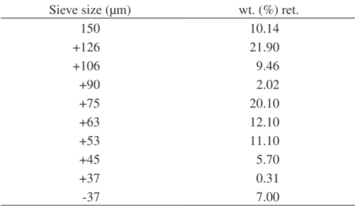
Atomized iron powder of -150 µm size was procured from M/s. The Sundaram Fasteners Limited, Hyderabad, India and graphite powder of 2 – 3 µm was supplied by M/s. The Ashbury Graphite
Mills Inc., Ashbury Warren County, New Jersey, USA. Analysis indicated that the purity of iron powder was 99.7% and the rest of it contains insoluble impurities. The characteristic of iron powder and iron – 0.8% carbon blend are shown in Table 1 and 2.
2.2. Blending, compaction and sintering
The required amount of powders corresponding to Fe-0.8%C were measured and blended in a pot mill along with porcelain balls of ratio 1:1 by weight for a period of 20 hours in order to obtain a homoge-neous mix. This powder blend was further compacted on a 1.0 MN capacity hydraulic press in the pressure range of 430 ± 10 Mpa to obtain the initial fractional theoretical density of 0.86 ± 0.01. These green compacts were sintered in an electric muffle furnace at tem-perature range of 1150 ±10 °C and maintained for 90 minutes. In order to avoid oxidation during sintering the compacts were ceramic coated. These sintered preforms were allowed to cool inside the furnace itself till they attained ambient condition.
2.3. Cold deformation
Sintered and furnace cooled preforms were machined to such a dimension so as to provide the preforms of constant initial aspect ratio of 0.40. Initial dimension of the cylindrical preform were measured using digital vernier caliper and these measured geometries were used to calculate the initial density. Preforms of Fe-0.8%C were axially deformed on a flat die set in the incremental loading step of 0.04 MN each under different lubricating constraints such as nil/no, graphite and zinc stearate lubricants respectively. Dimensional measurements such as deformed height, deformed diameters (includes bulged and contact) were carried out simultaneously at every step of deforma-tion, the density measurements were carried out using Archimedean principle15. Data thus obtained have been used to calculate various parameters so as to establish the behaviour of applied stresses with respect to continuous deformation and densification. Further, an attempt has been made to establish the technical affirmation for the enhancement of strain hardening during continuous deformation and densification of the sintered eutectoid preforms.
2.4. Parameters calculated
From the experimental data, the following parameters were calculated:
a) True height strain = ln(H0/Hf) b) True diameter strain = ln(Dc/D0) c) Fractional theoretical density = ρf/ρth
d) Engineering stress = P/A0, where A0 = π (D02)/4 e) True stress = P/Ac; where Ac = π (Dcf2)/4 f) Poisson’s ratio = (ln(D0/Dc))/(ln(Hf/H0))
Where, H0 is initial height of the preform; Hf is forged height of the preform; ρf is forged density of the preform; ρth is the theoretical density of the selected composition; Dc is forged contact diameter of the preform; D0 is initial diameter of the preform; P is applied load on the preform; A0 is the original area of cross section of the preform before it is forged. Ac is the area of cross section at contact diameter of the preform after forged.
3. Results and Discussion
3.1. Stresses and deformation
Applied stresses includes both engineering and true stresses, which can be defined as the resistance to deformation offered by the material(preform) with respect to original area of cross section(before deformation) and instantaneous area of cross section during deforma-tion respectively. The instantaneous dimensions of deforming preform X
X H0
D0
(a) Initial cylinder (b) Instantaneous barrel
XX Axis of symmetry
Relatively undeformed zones
P
Dc
Db
X Top contact face
Hf
Bottom contact face
Figure 1. Schematic representation of upset forging test specimen before
have been measured after the end of each step of incremental loading using digital vernier caliper. In order to establish the relationship on applied stresses as a function of continuous deformation a plot was constructed between engineering and true stresses against true height strain, which is shown in Figure 2.
The three different mechanisms can be described invariably for all the lubricating conditions that the first stage shows little rise in stress value, because the material starts offering resistance to deformation which means the initial application of load is just insufficient to deform the initial packing of sintered preform. However, in second stage, an extended deformation took place at uniform pace this influence the stress rise at steady state. In addition to the height strain, the diametrical spread out also takes place through out the deformation as the rise of true stress values are evident, however lateral expansion was substantial for the given induced strain in zinc stearate followed by graphite and dry friction respectively. Further, it is interesting to note that the divergences between engineering and true stresses are virtually distinct at the end of second stage (i.e., w.r.t. engineering stress curves 0.1 to 0.7 height strain value). This revealed the fact that up to second stage the height strain are substantial, thereafter the domination of diametrical strain occupies in the deforming preform. The third or final stage shows quite pronounced rate of engineering stress, which was not the fact for true stress, nevertheless it exhibits an index of strain hardening that made to resist the deformation little substantial.
3.2. Stresses and densification
In general, strength of any material can be broadly described as the ability of a material to withstand externally applied load up to its fracture. It is well established that the strength of P/M preform is governed by the maximum density that attained and the mode by which the density being attained. By virtue of the above phenom-ena, it can be claimed that the degree of material resistance against deformation is a function of attained density. Therefore, a plot has been constructed between applied stresses and percentage fractional theoretical density for Fe-0.8%C- steel preforms and is shown in Figure 3. The influence of friction conditions is highlighted on a constant aspect ratio preforms during deformation. Although, the general behaviour of curves plotted in Figure 3 is as similar to that
Table 1. Characterization of Iron powder and eutectoid steel blend.
Si. No. Property Iron powder and Powder blend
Iron Fe-0.8%C
1. Apparent Density (g/cc) 2.96 2.87
2. Flow rate, (s/100 g) by Hall Flow Meter 56.00 54.00
3. Compressibility (g/cc) at pressure of 430 ±10MPa 6.55 6.50
Table 2. Sieve size analysis of iron powder.
Sieve size (µm) wt. (%) ret.
150 10.14
+126 21.90
+106 9.46
+90 2.02
+75 20.10
+63 12.10
+53 11.10
+45 5.70
+37 0.31
-37 7.00
0 400 800 1200 1600 2000 2400
0.0 0.2 0.4 0.6 0.8 1.0 1.2
Engineeing and true stresses (Mpa)
True height strain N E 0.40
G E 0.40 Z E 0.40 N T 0.40 G T 0.40 Z T 0.40
Figure 2. Relationship between applied stresses and the true height strain of
sintered Fe-0.8%C P/M preform of 0.40 initial aspect ratio under the influ-ence of lubricants. N: Nil lubricant, G: Graphite Lubricant, Z: Zinc Stearate Lubricant, E: Engineering Stress, T: True Stress.
0 400 800 1200 1600 2000 2400
84 86 88 90 92 94 96 98 100
Fractional theoretical density (%)
Applied stresses (Mpa)
N E 0.40 G E 0.40 Z E 0.40 N T 0.40 G T 0.40 Z T 0.40
Figure 3. Relationship between applied stresses and the % fractional
theoreti-cal density for Fe-0.8%C sintered P/M preform of 0.40 initial aspect ratio under the influence of lubricants. N: Nil lubricant, G: Graphite Lubricant, Z: Zinc Stearate Lubricant, E: Engineering Stress, T: True Stress.
on an average 98-99% density) by the different kinetics of particles such as translation, rotation and transformation with in the pores, due to the induced strain during deformation. The remaining pores would attain thermodynamically stable state and it is expected to behave as a second phase particle. Any application of extensive load will deform both material as well as pores at same pace laterally outwards. Thus, the extensive application of load in upsetting mode of deformation will yield the pores as crack formation at the free surfaces of deforming preform. The diametrical increase of preform during deformation to bear the load is the cause for the difference in engineering and true stress values and this effect is highly pronounced at the final stage of deformation. Another important point to be noticed is that the stress/ load at which the crack opening is originated should be identified in order to suggest the introduction of circumferential constraint (i.e., repressive mode of deformation) to reweld the crack opening and thus to produce metallurgically sound product. In regards with influence of lubricants, both graphite and zinc stearate extended the deformation before the maximum density attained by the preform. However, the value of applied stress was relatively low at any instant of density attained by the preform, which is the index of conformity that strength imparted or strain hardening induced is minimum when lubricants (i.e., graphite and zinc stearate) employed during deformation.
3.3 Strain hardening characteristics
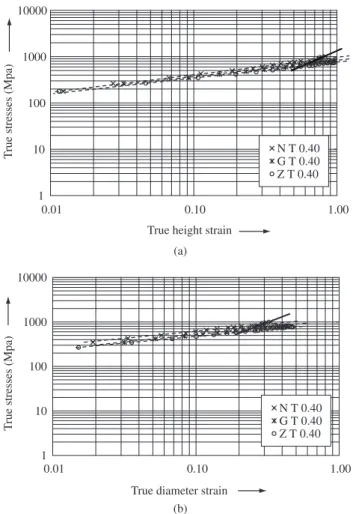
An attempt has been made to determine the strain-hardening ex-ponent graphically for Fe-0.8%C P/M preforms in order to describe its effect during cold deformation under the influence of lubricants. Thus, the flow curve was plotted in log – log scale to establish the linear relationship, by the process strain hardening (i.e., slope) can be easily determined. Figures 4a and b are the plots drawn between true stress in log scale to the true height strain and true diameter strain in log scale respectively for three different lubricating constraints.
The curve corresponding to nil lubricant constraint exhibits two different mechanisms shown in dashed line and continuous line and represented as segment 1 and segment 2 respectively. Whereas for graphite and zinc stearate lubricants, the respective curve technically follows single mechanism, which is shown by dashed line itself. The slope of the straight line in figures are equal to strain hardening expo-nents (n) in the expression σ = kεn, where σ is true stress, k is strength coefficient and ε is true strain. However, the slope of each curve has been determined by measuring the angle ‘θ’ through graphically with horizontal axis, which are presented in Table 3.
The critical observations of Figure 4a and 4b reveals that strain hardening can highly be imparted for the preform deformed under nil lubricating condition through continuous deformation up to its maximum densification (i.e., prior to crack formation in the preform). Nevertheless, graphite and zinc stearate lubricants only extend the deformation without substantial improvement in strain hardening. These figures will not reveal strain hardening exponent for each step of strain induced during deformation, however this supports the theory described for Figures 2 and 3. Further, it can be observed from Table 3 is that the slope value obtained for true height strain and true diameter strain at the first segment are almost in par with one another which exhibits the fact that work hardening takes place both in linear and in lateral direction as well. Conversely, it can be proved that densification takes place in both axial as well as in transverse direction due to the induced strain. This conforms to the findings of earlier investigation16.
The relationship established for applied stress with continuous deformation and densification revealed that the stress rise being enhanced with the enhancement of the strain and density attained by the preform. This is due to the increase of work hardening during deformation. In order to ascertain the established relationship, further
Table 3. Strain hardening co-efficient of flow curves.
Lubricants Employed
Segments Slope (θ) in Degrees
θh θd
Nil 1 6.6 5.8
2 22.6 20.9
Graphite 1 6.5 6.1
2 -
-Zinc Stearate 1 6 5
2 -
-θhandθd are the slopes or angle of flow curves determined with true height
strain and true diameter strain respectively.
Figure 4. a) Flow curve between true stresses and true height strain in log, log
scale; and b) Flow curve between true stresses and true diameter strain in log, log scale. Dashed line: Segment 1; Continuous line: Segment 2.
1 10 100 1000 10000
0.01 0.10 1.00
T
rue stresses (Mpa)
True diameter strain
N T 0.40 G T 0.40 Z T 0.40
(b) 1
10 100 1000 10000
0.01 0.10 1.00
True height strain
T
rue stresses (Mpa) N T 0.40
G T 0.40 Z T 0.40
(a)
plot have been constructed between instantaneous strain hardening exponent (ni) against percentage fractional theoretical density, true height strain and true stress respectively shown in Figures 5, 6 and 7. The theoretical descriptions for the determination of ‘ni’ has been developed from the plastic flow equation (σ = kεn) of fully dense material with little modification in order to suit for P/M materials, which are as follows.
0.0 1.0 2.0 3.0 4.0 5.0
84 86 88 90 92 94 96 98 100
N G Z
ni
Fractional theoretical density (%)
Figure 5. Relationship between instantaneous strain hardening exponent (ni)
and % fractional theoretical density.
0.0 1.0 2.0 3.0 4.0 5.0
0.00 0.20 0.40 0.60 0.80 1.00 1.20
N G Z
ni
True height strain
Figure 6. Relationship between instantaneous strain hardening exponent (ni)
and true height strain.
0.0 1.0 2.0 3.0 4.0 5.0
0 200 400 600 800 1000 1200
N G Z
ni
True stresses in MPa
Figure 7. Relationship between instantaneous strain hardening exponent (ni)
and true stresses.
(1)
(2)
Dividing the Equation 1 by Equation 2, the following expression is obtained
(3)
Taking natural logarithm on both sides of Equation (3), it fol-lows,
(4)
Equation 4 can further simplify into
(5)
Equation 5 can be utilized for determining the instantaneous strain hardening exponent from the experimental data corresponding to stress and strain.
Figures 5, 6 and 7 uniquely express that the degree of increase of strain hardening is of three stages. Initially, strain hardening exponent increases slightly followed by an extended steady state and finally it attains the peak (the similar characteristic observation was found in Figures 2 and 3). However, the last stage was highly pronounced in case of nil lubricant condition. The same was not true for graphite and zinc stearate lubricating conditions except at initial two stages. Obser-vation of Figures 5 and 6, uniquely expresses that preform deformed under dry friction is subjected to strain harden much faster as well as maximum, whereas preforms deformed under lubricating condition extended the deformation substantially and then it gets strain harden. In addition, the careful observation of these figures reveal that the values of strain hardening exponent for each induced strain and at-tained densification are observed to be higher for without employed lubricant condition in comparison to lubricant employed condition, which further ensures the truth that the rate of strain hardening was high in dry friction condition. However, Figure 7 exhibits, as an index of proof for the description stated for Figures 2 and 3 that the rise of stress values due to the hindrance of dislocation of particles will contribute directly to raise the strain hardening effect. Thus, it can be established that sintered preforms can be effectively cold deformed with ample strength induced due to work hardening effect.
4. Conclusions
It has been experimentally established and theoretically justified for the variation of engineering stress and the true stress w.r.t. the true height strain or the percentage fractional theoretical density exhibit-ing three different stages. The first stage exhibit the initial resistance of the preforms against deformation followed by the collapse of the pores and enhancement in densification, whereas the third stage cor-responded to the extensive work hardening and ultimately resulting under the extreme cases as the appearance of cracks on the free sur-faces of the deforming preforms. Thus, the ultimate stage restricts the limiting conditions of deformation and demanding for the introduction of repressing action to seal the surface appearing cracks.
preforms. Whereas, the application of lubricants has facilitated an extended deformation with the marginal increase of strain hardening up to its maximum theoretical densification attained or the surface cracks appears at the deforming preforms. Thus, sintered preforms can be successfully cold deformed with substantial strength induced due to the work hardening effect.
References
1. Ryuichiro Goto. Powder metallurgy growth in the automotive market.
Business Briefing: Global automotive manufacturing and technology.
2003: 44-45.
2. Miska Kurt H. In: Samuel Bradbury, editor. Powder metal parts. Ohio:
ASM Metals park; 1979: 1-9.
3. Pandey KS. Salient characteristics of high temperature forging of ferrous
powder preforms. Key Engineering Materials. 1989; 465: 29-31.
4. German RM. Powder Metallurgy of Iron and Steel. New York: John Wiley
& Sons Inc; 1998. p. 276-308.
5. Lawley A. In.: Gilbert Y. Chin, editor. Advances in powder technology.
New York: ASM Materials Science Seminar, ASM; 1982.
6. Kuhn HA, Downey CL. How flow and fracture affect design of preforms
for powder forging. International Journal of Powder Metallurgy and
Powder Technology. 1974; 10(1): 59-66.
7. Kuhn HA. Powder metallurgy processing. New York: Academic press;
1978. p. 99-138.
8. Hansen. N. Dispersion strengthened aluminium products manufactured
by powder blending. Powder Metallurgy. 1969; 12(23): 23-44.
9. Narayanasamy R, Pandey KS. Some aspects of work hardening in sintered
aluminium – iron composite preforms during cold axial forming, Journal
of Material Processing Technology. 1998; 84: 136-142.
10. El Wakil SD. Plasticity theory of sintered iron powder compacts.
Proceed-ings of The 15th International Conference on Machine Tool Design and
Research; Birmingham, UK, London: Macmillan; Sep 1974. p. 645.
11. Ball WG, Higher FW, Mckotch RA, Pfingstler HD. In: Edward N. Aqua,
Charles I. Whitman. editors. Advances in Powder Metallurgy and
Par-ticulate Materials. 1994. 3: 71-80.
12. Ball WG. New die – wall lubrication system. International Journal of
Powder Metallurgy 1997; 33(1): 23-30.
13. Narayanasamy R, Pandey KSA study on the barreling of sintered iron
preforms during hot upset forging. Journal of Material Processing
Technology. 2000; 100: 87-94.
14. Huppmann WJ, Brown GT. The steel powder forging process – a general
review. Powder Metallurgy 1978; (2): 105-112.
15. Moyer KH. Measuring density of P/M materials with improved precision.
International Journal of Powder Metallurgy and Powder Technology.
1979; 15: 33-42.
16. Pandey KS. Some investigations on the cold deformation behaviour of
sintered aluminium-4%copper alloy powder preforms. Journal of Powder