DO:
D 10.1590/S1516-14392011005000074
Strain Hardening Behaviour in Forming of Sintered Iron-0.35% Carbon Powder
Metallurgy Preform During Cold Upsetting
Sumesh Narayan*, Ananthanarayanan Rajeshkannan
Mechanical Engineering, School of Engineering and Physics, Faculty of Science,
Technology & Environment, The University of the South Pacific,
Laucala Campus, P.O. Box 1168, Suva, Fiji
Received: August 10, 2010; Revised: July 28, 2011
A complete experimental investigation on the instantaneous strain-hardening behaviour of powder metallurgy preforms of Fe-0.35%C was carried out. The strain hardening behaviour of the above-mentioned P/M sintered steel preforms with aspect ratio of 0.4 and 0.6, respectively, under triaxial stress state condition was determined by cold upsetting under nil/no and graphite lubricant conditions. The instantaneous strain hardening value (ni),
strength coeficient (Ki), and the stress as a function of strain and densiication were obtained and analyzed. Further, a relation is obtained from a semi-log plot of stress against relative density. This was analyzed to study the hardening behaviour due to the densiication as applied stress is a function of induced strain as well as of densiication in the powder metallurgy materials.
Keywords: strain hardening exponent, density hardening exponent, strength coefficient, densification
1. Introduction
Powder metallurgy (P/M) is a near-net shape metal forming process used to manufacture unique and innovative part to close tolerance. This technology is conducive for nearly any material that can be processed in powder form. The technology is sometimes the only manufacturing method used to produce parts with porous materials, composite materials, refractory materials and special high duty alloys. The automotive industry is the key consumer of P/M parts due to the cost-effective nature of the process1-3. On a
usual P/M production sequence (primary processes), the powders are mixed or blended and compressed into the desired shape and then heated to cause bonding of the particles into a hard, rigid mass. A known limitation of this route is the large number of small voids left in components after sintering. The P/M parts produced by the
primary processes are low in density since they contain suficiently
large amounts of pores that act as a site of stress risers and stress concentrations resulting in crack initiation and propagation when subjected to mechanical application. Hence, these parts cannot be used for heavy duty applications. A secondary deformation process such as pressing or repressing, powder extrusion, powder rolling, and
iniltration is used in order to enhance the mechanical properties of
sintered powder materials. Plastic deformation is the main means to improve the performance of sintered ferrous material and to obtain
the inal product. In general the preform produced by the conventional
process will undergo a large degree of plastic deformation with enhanced levels of densification4-6. Even though the plastic
deformation of powder preforms is similar to that of conventional fully dense material, additional complications arise because of substantial amount of void fractions. Therefore, deformation of a porous material
is a function of both the induced stress and densiication, which is
not the case in fully dense material7,8.
With the application of axial tensile stress the pores will grow
and densiication will decrease, whereas with the application of axial compressive stress the densiication enhances as the pores
will collapse and ultimately close. Ot has been reported9 that as
the density increases, the imposed stress also increases. On powder preform forging, a porous material would experience the usual strain or work hardening characteristics as well as geometrical work hardening10. However, the rate of increase in the stress value
with respect to strain is greater than what would be observed in a pore free material of the same composition under identical testing conditions. This is because the continued reduction in the porosity level during upsetting increases the load bearing cross sectional area. This in turn increases the stress required for further deformation, resulting in matrix and geometric work hardening behaviour. Thus, the total strain or work hardening behaviour of the porous preform
is due to the combined effects of induced densiication and induced
strain during cold forging11-13. Lubrication also plays an important role in the metal low particularly in cold upsetting and affects the densiication and forming limit mechanisms. A good lubrication
improves the quality of products through the reduction of defects
and improvement in the dimensional accuracy and surface inish8,14.
Narayanasamy et al.15 investigated the instantaneous strain-hardening
behavior of an aluminum-iron powder metallurgy composite with various percent of iron contents and for the various stress state conditions with two different aspect ratios. Ot is well known that both
the strain hardening exponent and the strength coeficient are basic
mechanical behaviour performance parameters of metallic materials. Therefore, the strain-hardening exponent is an important parameter
relecting a material’s hardening property and its determination is of
great importance16. Ot has been found10,17 that the initial geometry of
the powder metallurgy preform has an effect on the strain hardening exponent (ni) and strength coeficient (Ki).
The present investigation is aimed to experimentally study the strain hardening behaviour of powder metallurgy preforms of Fe-0.35%C with the influence of aspect ratio and lubricant
conditions, namely, nil/no, zinc stearate and graphite lubricant
respect to percent fractional theoretical density and true height strain. Further, the technical relationship was established that exists
between instantaneous strength coeficient (Ki) with respect to percent fractional theoretical density and true height strain. Stress-strain and
stress-densiication relationship was also established for the powder metallurgy preforms deformed under nil/no, zinc stearate and graphite
lubricant conditions for 0.4 and 0.6 initial aspect ratio. Ot is well known that for P/M materials stress is a function of induced strain
and densiication, hence, a relationship was obtained from a semi-log
plot of stress against relative density.
2. Experimental Details
2.1. Materials and characterization
Atomized iron powder of less than or equal to 150 µm size and graphite powder of 2-3 µm size were used in the present investigation.
Analysis indicated that the purity of iron was 99.7% and the rest were
insoluble impurities. The characteristic (apparent density, low rate and particle size distribution) of iron powder and Fe-0.35%C blends
are shown in Tables 1 and 2.
2.2. Blending, compaction and sintering
A powder mix corresponding to Fe-0.35%C was taken in a stainless steel pot. The powder was mixed with porcelain balls (10-15 mm diameter) with a ratio of 1:1 by weight. The pot containing the blended powder was subjected to the blending operation by
securely tightening and then ixing it to the pot mill. The mill was
operated for 20 hours to obtain a homogenous mix. Green compacts of 28 mm diameter with 12 mm of length were prepared. The powder blend was compacted on a 1.0 MN hydraulic press using a suitable die, a punch and a bottom insert in the pressure range of 430 ± 10 MPa to obtain an initial theoretical density of 0.84 ± 0.01. On order to avoid oxidation during sintering and cooling, the entire surface of the compacts was indigenously formed ceramic coated. These ceramic
coated compacts were heated in the electric mufle furnace with
temperature a of 1200 °C ± 10 °C. At this temperature the compacts were sintered for 90 minutes followed by furnace cooling.
2.3. Cold deformation
Sintered and furnace cooled preforms were machined to such a dimension so as to provide height-to-diameter ratio of 0.4 and 0.6, respectively. The initial dimensions of the cylindrical preforms were measured and recorded and used to calculate the initial density. Each
specimen was compressively deformed between a lat die-set in the
incremental loading step of 0.05 MN. This was done using 1 MN capacity hydraulic press under friction conditions, which included dry, unlubricated dies called nil/no lubricant condition and lubrication
consisting of graphite paste (i.e. graphite with acetone) and zinc stearate called graphite lubricant condition and zinc stearate lubricant
condition, respectively. The deformation process was stopped once a visible crack appeared at the free surface. Dimensional measurements such as deformed height, deformed diameters (including bulged and contact) were carried out after every step of deformation using digital vernier caliper and the density measurements were carried out using the Archimedes principle. Experimental results were used to calculate
the low stress, true height strain, percentage theoretical density and instantaneous strength coeficient (Kiand Ci), instantaneous density hardening index (mi) and instantaneous strain hardening exponent (ni).
3. Theoretical Analysis
Using the measured upsetting parameters the following mathematical expressions are used to determine other upsetting parameters (stress, strain, instantaneous strain hardening and strength
coeficient) for triaxial stress state. The expression for true axial stress
and strain for powder metallurgy materials are as follows:
z
load contact surface area
σ = (1)
ln o z f h h
ε =
(2)
and true hoop strain is
2 2 2 2 ln 3 b c o D D D θ +
ε =
(3)
where ho is the initial height of the preform; hf the forged height of the preform; Db the forged bulged diameter of the preform; Dc the forged contact diameter of the preform; Do the initial diameter of the preform.
According to Narayansamy et al.15, the hoop stress (σ θ) under
triaxial stress state condition can be determined as given below:
2
2 2
2
2 2 z
R
R R
θ
α +
σ = σ
− + α
(4) where, z d d θ ε α =
ε , dεz is the plastic strain increment in the axial direction and dεθ is the plastic strain increment in the hoop direction. The effective stress and the effective strain are determined by the following expressions in terms of cylindrical coordinates as explained elsewhere18,19 under triaxial stress state for axisymmetric upset forging
condition (σr = σθ).
0.5
2 2 2 2
2
2 ( 2 )
2 1
z z
eff
R R
θ θ θ
σ + σ − σ + σ σ
σ =
−
(5) Table 1. Characterization of iron powder.
Si. No. Property Oron Fe-0.35%C
Blend
1. Apparent Density (g/cc) 3.38 3.37
2. Flow rate, (s/50 g) by Hall Flow Meter 26.3 28.1
3. Compressibility (g/cc) at pressure
of 430 ± 10 MPa 6.46 6.26
Table 2. Sieve size analysis of iron powder.
Sieve size (µm) Wt. (%) Ret.
0.5 2
2 2 ( 2 ) 2
2
[( ) ( ) ] [1 ]
3(2 ) 3
z
eff z z R
R
θ
θ θ
ε + ε
ε = ε − ε + ε − ε + −
+
(6)
Equations 5 and 6 are utilized to determine the strain hardening parameters as explained here. An attempt was made to use plastic low
(Ludwik) equation σ = Kεn, with little modiication for P/M preforms to determine the instantaneous strength (Ki) and instantaneous strain hardening (ni), where σ is true effcetive stress; ε is true effective strain; K is strength co-eficient and n is strain hardening exponent. The theoretical description follows:
Assuming consecutive effective load on the preform were
speciied as 1, 2, 3,..., (m-1) and m. Now the plastic low equation
can be written as follows:
n
m K m
σ = ε (7)
1 n 1
m− K m−
σ = ε (8)
Subtracting Equations 7 and 8, the following expression can be obtained
1 ( n n 1)
m m− K m m−
σ − σ = ε − ε (9)
The Equation 9 can further deduce into
1 1
m m
i n n
m m
K −
−
σ − σ =
ε − ε
(10)
Now, dividing the Equation 7 by Equation 8, the following expression is obtained
1 1 1
n n
m m m
n
m− m− m−
σ ε ε
= =
σ ε ε
(11)
Taking natural logarithm on both sides of Equation 11, it follows,
1 1
ln m ln m
m m
n
− −
σ ε
=
σ ε
(12)
Equation 12 can further simplify into
1 1 ln ln m m i m m n − −
σ
σ
=
ε
ε
(13)
Equations 10 and 13 can be utilized for determining the instantaneous strength coeficient and instantaneous strain hardening
exponent from the experimental data corresponding to stress and strain.
Further, from the semi-log plot of stress against relative density the following relationship can be deduced. The linear relationship can be expressed as
logσ =mR+logC (14)
where R is the relative density, m is the density hardening index and
C is the density strength coeficient. Equation 14 can be reduced to
it general form as
(mR)
σ =
Assuming consecutive effective load on the preform were
speciied as 1, 2, 3,..., (i-1) and i. Now Equation 15 can be written as
(mRi)
i Ce
σ = (16)
1
( )
1 i
mR
i− Ce −
σ = (17)
Dividing Equation 1 by Equation 2 gives
1 ( ) ( ) 1 i i mR i mR i Ce Ce − − σ =
σ (18)
Taking natural logarithm on both sides of Equation 18, it follows,
1 1
ln i ( i i )
i
m R R− −
σ
= −
σ
(19)
Equation 19 can further simplify into
1 1 ln i i i i i m R R − −
σ
σ
=
− (20)
Using Equation 20, the instantaneous density hardening index (mi) can be determined. Further, subtracting Equation 16 from Equation 17 the following expression can be obtained:
1
1 ( mRi mRi )
i i− C e e −
σ − σ = − (21)
Equation 21 can further be rearranged as:
1
1
i i
i i
i mR mR
C
e e −
−
σ − σ =
−
(22)
From the above Equation 22, the instantaneous density strength
coeficient (Ci) can be determined.
4. Results and Discussion
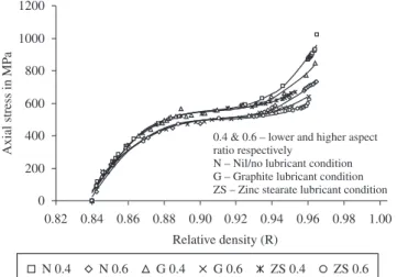
Cold working is one of the methods to promote strength in metals; in this case strain induced will be the prominent factor for a fully dense material. The same is true for P/M material too, however the additional factor that governs its behaviour is pore closure or density attained. Ot is well established8 that attaining full density along with the mode by which it is attained is a signiicant phenomenon that
governs the strength of P/M material. Thus, Figure 1 shows the relationship between axial stress and relative density for Fe-0.35%C P/M preform for two different aspect ratio cold deformed under three
different frictional conditions, namely, nil/no, graphite and zinc
stearate lubricant condition. The characteristics nature of the curves
is similar since as the densiication increases low stress also increases
continuously. Due to the continual application of the applied stress the pores present in the P/M material collapse and close enhancing
the densiication and increasing the strength of the P/M material
by cold deformation. To further deform the P/M preforms require additional load, hence, increasing the applied load as the deformation and density increases to near theoretical density. Ot can be seen that
the axial stress increases rapidly during the initial and inal stages of deformation. The initial application of load is not suficient to
Figure 1. Variation of axial stress and relative density for cold deformed Fe-0.35%C preform.
Figure 2. Variation of axial stress in log-scale and relative density for cold deformed Fe-0.35%C perform.
Figure 3. Variation of axial stress and axial strain for cold deformed Fe-0.35%C preform.
Table 3. Values of mi and Ci for Fe-0.35%C.
Aspect ratio
Mechanism of density hardening
Frictional constraints
Nil/no lubricant Graphite lubricant Zinc stearate
mi Ci mi Ci mi Ci
0.4
1 28.57 6.18 × 10⁻⁹ 28.57 6.18 × 10⁻⁹ 28.57 6.18 × 10⁻⁹
2 6.36 1.80 6.36 1.80 6.36 1.80
3 1.50 142.86 1.50 142.86 1.50 142.86
4 5.11 5.99 3.47 25.82 1.44 159.20
0.6
1 28.57 6.18 × 10⁻⁹ 28.57 6.18 × 10⁻⁹ 28.57 6.18 × 10⁻⁹
2 5.96 2.11 5.96 2.11 5.96 2.11
3 0.62 286.46 0.62 286.46 0.62 286.46
4 4.60 7.87 3.28 26.02 2.27 65.21
due to the strain hardening of the material. Further, it is observed for any value of percent fractional theoretical density, the lower aspect ratio preform deformed under nil/no lubricant condition experience higher stress values compared to higher aspect ratio preform. Further,
the effect of frictional constraints is only evident during the inal
stages of deformation and it can also be noted that graphite lubricant
provides better densiication characteristics in comparison to zinc
stearate lubricant condition.
Powder metallurgy preforms when subjected to applied load during cold upsetting deform as well as increase in density and hence, does not conform to volume constancy principle unlike in the fully dense material. Therefore, stress and strength of the P/M
materials depends on both strain and densiication. Figure 2 shows the
relationship between axial stress in log-scale and relative density for Fe-0.35%C P/M preform for two different aspect ratio cold deformed under three different frictional conditions, namely, nil/no, graphite and
zinc stearate lubricant condition. The relationship between true stress
and relative density follows a relationship which can be expressed as (mR)
Ce
σ = where C referred to as density strength coeficient and m
referred to as density hardening exponent and these two parameters
can be utilized to understand the stress densiication phenomenon
in enhancing the strength of the P/M material via cold deformation. The characteristics nature of the curves shown in Figure 2 is similar and follows four different mechanisms. Table 3 shows the values of
mi and Ci obtained from Figure 2 for two different aspect ratios and
three different frictional constraints. A signiicant high and low values
Figure 4. a, b) Microstructure view at diametric extreme of the preform deformed under nil/no and graphite employed lubricant respectively.
Figure 5. Variation of strain hardening exponent and relative density for cold deformed Fe-0.35%C preform.
Figure 6. Variation of strain hardening exponent and axial strain for cold
suficient to deform the P/M preform and during the initial stages
of deformation the P/M preform was able to resist the applied load until it exceeded the initial yield stress of the P/M material. Ot can be seen that an inverse relationship exists between the density hardening exponent (mi) and density strength coeficient (Ci) (as mi increases Ci
decreases and vise versa). Oncreasing the frictional constraints and reducing the aspect ratio increases the density hardening exponent (mi), however, the density strength coeficient (Ci) reduces.
Figure 3 shows the relationship between axial stress and axial strain for Fe-0.35%C P/M preform for two different aspect ratio cold deformed under three different frictional conditions, namely,
nil/no, graphite and zinc stearate lubricant condition. For any given
true height strain the axial stress increases with increasing frictional constraints and reducing aspect ratio. The lateral deformation is more
pronounced in the graphite and zinc stearate employed preforms.
From Figure 4 it can be seen that the pores (black color) are more elongated for graphite employed lubricant when compared to nil/ no lubricant condition. This is the reason for enhanced axial stress values for lower aspect ratio preform deformed under nil/no lubricant condition. Ot can also be noted that graphite lubricant provides better
deformation characteristics in comparison to zinc stearate lubricant
condition.
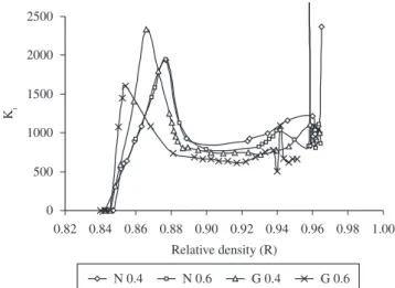
Figures 5 and 6 show the relationship between strain hardening exponent against relative density and axial strain, respectively, for Fe-0.35%C P/M preform for two different aspect ratio cold deformed under two different frictional conditions, namely, nil/no and graphite lubricant condition. The characteristics nature of the curves follow similar trend, a sudden increase in strain hardening exponent with
little densiication and deformation followed by a sudden decrease
in the strain hardening exponent values and then it follows a gradual decrease for 0.87 to 0.93 relative density and for 0.09 to 0.4 true height strain, respectively. Further, up to 0.955 relative density and 0.78 axial strain, a gradual increase in strain hardening exponent is seen. After 0.955 relative density and 0.78 true height strain a
mild to heavy luctuations in strain hardening exponent values are
Figure 7. Variation of strength coeficient and relative density for cold deformed Fe-0.35%C preform.
Figure 8. Variation of strength coeficient and axial strain for cold deformed Fe-0.35%C preform.
initially are elongated (Figure 4) due to the application of applied load. This is the reason for a decrease in strain hardening exponent and after the effective closure of pores the strain hardening exponent
increases. During the inal stages of deformation the P/M material
approaches near theoretical density with 4 to 5% porosity left, which
are dificult to close. The P/M preforms are highly strain hardened
at this point, hence, to further close the remaining pores requires
high applied stress which in turn signiicantly increases the strain hardening values. When these remaining pores collapse it signiicantly reduces the strain hardening values. This causes luctuations in the strain hardening values in the inal stages of deformation. Further,
from Figures 5 and 6, it is noticed that the strain hardening values are enhanced for nil/no lubricant condition and lower aspect ratio preform in comparison to graphite lubricant condition and higher aspect ratio
preform, respectively, and the luctuations of strain hardening values
are severe in the case of nil/no lubricant condition. Ot can be concluded that strain hardening is promoted in the P/M preform by increasing the frictional constraints and reducing the aspect ratio.
Figures 7 and 8 shows the relationship between strength
coeficient against relative density and axial strain, respectively, for
Fe-0.35%C P/M preform for two different aspect ratio cold deformed under two different frictional conditions, namely, nil/no and graphite lubricant condition.The curves plotted in Figures 7 and 8 show that
the strength coeficient increases rapidly at low values of densiication and strain rate followed by a decrease in the strength coeficient
values. Thereafter from 0.89 relative density to 0.96 relative density and 0.18 axial strain to 0.78 axial strain, respectively, the strength
coeficient slowly increases at a steady rate and after 0.96 relative density and 0.78 axial strain a luctuation in the strength coeficient values are noticed. The luctuations in the strength values are severe
for nil/no lubricant condition in comparison to graphite employed lubricant. The slope of the curve during the intermediate stage is higher for nil/no lubricant condition and lower aspect ratio preform compared to graphite employed lubricant condition and higher aspect ratio preform. Ot can be said that increasing the frictional constraints
and reducing aspect ratio enhances the strength coeficient.
5. Conclusions
The major conclusions have been drawn from the present investigations that are as follows:
• Axial stresses increased with the enhancement of deformation
and densification; followed three different mechanisms of deformation irrespective of frictional constraints and
aspect ratio. Initial and inal stage exhibits high resistance
to deformation. However, during the intermediate stage stresses rise at a steady rate due to extended deformation and
densiication;
• The strain hardening and strength coeficient in the P/M
preform were improved when the frictional constraints were increased and aspect ratio was reduced;
• Faster and effective closure of pores is found to be higher when
preforms are deformed under nil/no lubricant condition;
• Two new parameters namely density hardening exponent (mi)
and density strength coeficient (Ci) are introduced to study
hardening behaviour in P/M material by densiication.
References
1. Lindskog P. Economy in car-making - powder metallurgy, Global Automotive Manufacturing and Technology, Technology & Services. London: Business Brieing; 2003.
2. Ryuichiro G. Powder metallurgy growth in the automotive market, Global Automotive Manufacturing and Technology, Materials. London: Business Brieing; 2003.
3. Rosochowski A, Beltrando L and Navarro S. Modeling of density and dimensional changes in re-pressing/sizing of sintered components. Journal of Materials Processing Technology. 1998; 80:188-194. http://dx.doi.org/10.1016/S0924-0136(98)00184-8
4. Hua L, Qin X, Mao H and Zhao Y. Plastic deformation and yield criterion for compressible sintered powder materials. Journal of Materials Processing Technology. 2006; 180:174-178. http://dx.doi.org/10.1016/j. jmatprotec.2006.06.001
5. Liu Y, Chen LF, Tang HP, Liu CT, Liu B and Huang BY. Design of powder metallurgy titanium alloys and composites. Material Science Engineering A. 2006; 418:25-35. http://dx.doi.org/10.1016/j.msea.2005.10.057
6. Kandavel TK, Chandramouli R and Ravichandran M. Experimental study on the plastic deformation and densiication characteristics of some sintered and heat treated low alloy powder metallurgy steels. Materials and Design. 2010; 31:485-492. http://dx.doi.org/10.1016/j. matdes.2009.06.048
Appendix 1. Notation.
C Carbon εeff Effective strain
Fe Oron K Strength co-eficient
εθ True hoop strain Ki Instantaneous strength co-eficient
εz True axial strain n Strain hardening exponent
R Fractional theoretical density ni Onstantaneous strain hardening exponent
σz Axial stress C Density strength coeficient
σθ Hoop stress Ci Instantaneous density strength coeficient
σr Radial stress m Density hardening exponent
σeff Effective stress mi Onstantaneous density hardening exponent
8. Rajeshkannan A and Narayan S. Strain hardening behaviour in sintered Fe-0.8%C-1.0%Si-0.8%Cu powder metallurgy preform during cold upsetting. Journal of Engineering Manufacture. 2009; 223:1567-1574. http://dx.doi.org/10.1243/09544054JEM1587
9. Rajeshkannan A, Pandey KS, Shanmugam S and Narayanasamy R. Sintered Fe-0.8%C-1.0%Si-0.4%Cu P/M preform behaviour during cold upsetting. Journal of Iron and Steel Research, International. 2008; 15:81-8. http://dx.doi.org/10.1016/S1006-706X(08)60254-X
10. Narayanasamy R and Pandey KS. Some aspects of work hardening in sintered aluminium - iron composite preforms during cold axial forming. Journal of Materials Processing Technology. 1998; 84:136-142. http://dx.doi.org/10.1016/S0924-0136(98)00088-0
11. Kahlow KJ. Void behaviour as influenced by pressure and plastic deformation. Onstitute for Metal Forming Report, Lehigh University; 1971.
12. Taha MA, El-Mahallawy NA and El-Sabbagh AM. Some experimental data on workability of aluminium-particulate-reinforced metal matrix composites. Journal of Materials Processing Technology. 2008; 202:380-385. http://dx.doi.org/10.1016/j.jmatprotec.2007.07.047 13. Zhang XQ, Peng YH, Li MQ, Wu SC and Ruan XY. Study of workability
limits of porous materials under different upsetting conditions by compressible rigid plastic inite element method. Journal of Materials Engineering and Performance. 2000; 9:164-169. http://dx.doi. org/10.1361/105994900770346114
14. Simchi A. Effects of lubrication procedure on the consolidation, sintering and microstructural features of powder compacts. Materials and Design. 2003; 24:585-594. http://dx.doi.org/10.1016/S0261-3069(03)00155-9
15. Narayanasamy R, Ramesh T and Pandey KS. An investigation on instantaneous strain hardening behaviour in three dimensions of aluminium-iron composites during cold upsetting. Material Science Engineering A. 2005; 391:418-426. http://dx.doi.org/10.1016/j.msea.2004.09.018
16. Ebrahimi R and Pardis N. Determination of strain-hardening exponent using double compression test. Material Science Engineering A. 2008; 497:505-511.
17. Pandey KS. Some investigations on the cold deformation behaviour of sintered aluminium-4% copper alloy powder preforms. International Journal of Powder Metallurgy Science and Technology. 1991; 2:35-44.
18. Doraivelu SM, Gegel HL, Gunasekera JS, Malas JC, Morgan JT and Thomas Junior JF. New yield function for compressible P/M materials. International Journal of Mechanical Science. 1984; 26:527-535. http://dx.doi.org/10.1016/0020-7403(84)90006-7