163 __________________________
First Author- P Vinay, M.Tech (2nd year), NITK, Surathkal, pvinay92@gmail.com
Second Author- Srivatsa G R, MS (2nd year) University of Michigan, Dearborn, vatshuchcha@gmail.com
Third Author-Venkatesh Datta, Systems Engineer, Infosys Ltd., venkatesh_datta@yahoo.com
Fourth Author-Dinesh Kumar A, MSc (1st year), Chalmers University of Technology, dini1318@gmail.com
Fifth Author- Ramesha N, Systems Engineer, NTT DATA, rameshrohit5520@gmail.com
Design, Fabrication And Partial-Analysis Of A
2-Wheeler Prototype That Runs On Compressed Air
P Vinay, Srivatsa G R, Venkatesh Datta, Dinesh Kumar A, Ramesha N, Dr. H K Govindaraju
Abstract: The primary objective of the project is to create a prototype of a purely air powered motorcycle by retrofitting its internal combustion engine to run on compressed air. Firstly, the conventional spark plug was replaced with a solenoid valve. The solenoid valve was initially actuated using a reed switch and magnet duo, but then later replaced with an optical crank position sensor circuit due to reasons that include lack of control over the amount of air injected during each stroke and also for more precise control over the opening and closing of the valve. The torque, brake power, indicated power, air consumption rate of the engine under load are calculated. Separate mounts for the modified engine and the cylindrical storage unit are designed and analysed using Catia v4. Also, possible ways of future scope of the prototype are mentioned.
Index Terms: Catia, Combustion, Flywheel, Multi-vibrator, Pulse, Solenoid, Trimpot.
————————————————————
1.
INTRODUCTION
In this paper we shall talk briefly about the automotive industry, the prevailing technologies that are currently being used and future developments. We shall expand upon the importance of exploring alternative fuel sources and why we got the inspiration to pursue and explore the possibility of using compressed air to power prime movers. Almost all commercially available vehicles are powered using fossil fuels and almost all manufacturers are concentrating their R&D efforts in improving the efficiency of a decade old design! But recently, due to the looming fuel crisis, a lot of manufacturers woke up and decided that the future lies in renewable energy and hence have shifted their focus to this field. A lot of research has been and is currently being carried out in electric power, fuel cells, Kinetic energy recovery system (KERS), etc. but the same importance is not being given to compressed air power. In spite of all this, the internal combustion engine remains vital to almost all commercially available vehicles and is not yet expendable. This was the main factor which influenced our decision in taking up this project. The main motivation behind our project was to try and study different potential sources of renewable energy that can be used to power an automobile in an aim to reduce air pollution. The internal combustion engine generates power due to the rapid expansion of gases that occurs in its combustion chamber during its operation. The main idea behind this project is to emulate this process without resorting to the need of using fossil fuels. The phenomenon of downward pressure being applied on the piston is replicated using compressed air. The methodology adopted is unique as it aims at using an existing
conventional engine with a different source of power. Thus conventional moulds and manufacturing processes need not be modified to specifically suit our requirements and more importantly existing engines can be converted to run on compressed air. Our project mainly involves design and fabrication of specific parts necessary for the functioning of our vehicle that runs on compressedair [1], which prior to these modifications would be running on petrol. Hence the project is
titled ―Design and Fabrication of a 50cc two wheeler that runs on compressed air‖.
2.
WORKING PROCESS
A solenoid valve is attached to the spark plug port to take up the role of the fuel injection system. The timing is achieved using a reed [2] switch to actuate the solenoid valve as soon as the piston hits top dead centre (TDC). A magnet is attached to the outer casing of the flywheel which rotates in synchrony with the rotation of the crank. The magnet is mounted in such a way that it comes in close proximity to the reed switch, which has been rigidly anchored, only when the piston reaches TDC. As the magnet passes the reed switch, which is in normally open position, the magnetic flux cuts across the reed thereby causing the switch to close. This in turn causes the solenoid valve to open and allow high pressure air to flow into the combustion chamber thus pushing the piston downwards and forming the first power stroke. As the magnet moves further away from the reed switch, the magnetic action is no longer sufficient to close the reed and hence the flow of air into the combustion chamber is ceased. The momentum of the flywheel is sufficient to continue the rotation of the crankshaft during the upward stroke [3]. Also the emission of exhaust air occurs during this upward stroke. This process repeats continuously, hence providing useful power that can be used to drive the wheels using a suitable gearing mechanism.
3.
IMPROVEMENTS USING ELECTRONIC
TIMING CIRCUIT
The solenoid valve actuation and the pulse control is achieved using an optical crank position sensor circuit. The circuit mainly consists of vital components: optical emitter-receiver (OPB732), Astable multivibrator (LM555) [4], TIP 122 Darlington pair [5], 200kΩ Trimpot. The working is as explained below:
164 IJSTR©2015
disc has slots on the circumference. The OPB732 (Fig. 2) is mounted above the disc parallel to the crank shaft such that the light emitted by it is reflected back when the slot comes in between the emitter and receiver, opening up the barrier between them. These slots were positioned in such a way that they would reach the gap between emitter and receiver as soon as the piston leaves TDC. The receiving transistor then goes into the active region and starts to conduct current. This leads to a voltage drop. The entire setup is arranged such that the reflection of emitted light leads to the generation of a negative voltage drop which then acts as a triggering pulse to the multivibrator.
Fig. 1: Trigger Disc with slots
Fig. 2: Optical emitter-receiver (OPB732)
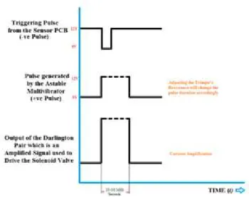
b) The circuits [6] in Fig. 4 and Fig. 5 are explained below: The negative trigger is detected by the astable multivibrator (connected in such a manner that it functions as a mono stable multivibrator). This in turn generates a positive clock pulse which is then transmitted to a Darlington pair (Fig. 3). The width of this pulse can be varied by varying the resistance of the Trimpot (this allows for freedom in deciding the injection pulse duration). The pulse generated is akin to a step input and dies after a predetermined amount of time thus regulating the maximum duration for which the solenoid remains open;
this ensures that the pulse doesn’t affect the upward motion of
the piston.
c) The pulse generated is amplified by the Darlington pair which is then used to drive the solenoid valve. The solenoid valve remains open for the duration of the electrical pulse.
Fig. 3: Graphical depiction of the response of the various components in the timing circuit to an external trigger
d) This process repeats continuously, hence providing useful power that can be used to power the wheels using a suitable gearing mechanism.
Fig. 4: Mother PCB
165
4.
CALCULATIONS AND RESULTS
4.1: Experimental calculations of torque:
An experiment was conducted in which a pipe was fastened to the centre of the crank, and a rope was tied to the
free end of the pipe. The free end of the rope was loaded with weights. The engine was then run on compressed air and the weights were lifted from the ground. The following observations were made:
Table 1: Experimental calculation of torque
Weights (kg)
Pressure range of compressed air(psi)
Lift (feet)
3 80-85 5
4 90 – 95 4
5 110 -115 Just off the
ground
(Height at which experiment was conducted = 6 ft) Experimental Torque, Texp= Force* Distance
pipe rope
exp
F
r
Wg
r
nt
T
where F= applied force (N) W= Weight (kg)
g= acceleration due to gravity (9.81 m/s2) rpipe= radius of pipe (0.01 m)
trope= thickness of rope (0.05 m)
n= number of turns (3)
Thus, Texp = 0.7357 Nm
4.2: Brake power:
Engine displacement– 50 cc Swept Volume, Vn = 50000 mm
3
Bore diameter, d = 48 mm Stroke length, l = 27.63 mm Engine RPM, n= 550 rpm
Brake power,
kW
60000
T
N
2
π
BP
expThus, BP = 42.37 W
4.3: Air consumption:
Assuming volumetric efficiency = 100%
Air flow in SCFM (Standard Cubic Feet per Minute) is given by:
1728
RPM
ci
nt
Displaceme
flow
Air
Air flow = 0.9709 scfm or Air flow = 27.495 lpm
4.4: Indicated power:
Indicated power,
kW
60000
LAN
P
IP
m Pm= Mean effective pressure Pm = 87.5 psi = 603291.262 N/mThus, IP = 276.49 W
4.5: Mechanical efficiency:
100
IP
BP
η
mech
Thus,ηmech=15.32 %
4.6: Trigger disc slot calculations:
Under load, at N = 400 rpm: 1 Rev = 1/400 = 0.0025*60 1 Rev = 2 Strokes and 1 Stroke = 75 ms
Circumference = 358 mm
Arc/second = 358/150 = 2.38 mm/ms 1ms --- 2.38 mm
Arc/second = 20*2.38
Thus, Arc = 47.6 mm
5.
PERFORMANCE CURVES
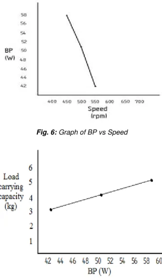
From the graph in Fig. 6, it is evident that at an optimum lower speed, a high output power is obtained and this value decreases with increase in speed. The graph in Fig. 7 shows that the load carrying capacity increases with increase in power output. From the experiment, we can infer that the engine successfully lifted 3kg and 4kg loads whereas with 5kg load it just managed to lift off the ground.
Fig. 6: Graph of BP vs Speed
Fig. 7: Graph of Load carrying capacity vs BP
6.
DESIGN ANALYSIS
166 IJSTR©2015
Fig. 8: Design of the engine mount
In case of the engine mount, a maximum translational displacement of 0.0113 mm is observed. This value is well within the allowances provided for displacement (Fig. 9).
Fig. 9:Engine mount: Displacement analysis
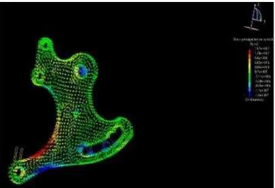
A Maximum Principal stress of 15.7MPa is observed along the edges (Fig. 10). The mount is made up of stainless steel, which has an ultimate tensile strength of 860 MPa and yield strength of 520MPa. Since the maximum stress is only 15MPa, the design is safe.
Fig. 10: Engine mount: Principal stress analysis
In case of the cylinder mount, at a uniformly distributed load of 100 kg, the mount deforms due to a displacement of 2.64 mm (Fig. 11). Hence the design is safe as long as the load acting is less than 90-95 kg.
Fig. 11: Cylinder mount: Displacement analysis
7.
CONCLUSIONS
a) Power developed and the torque provided by the engine is sufficient enough to pull a person weighing 85 kgs. This shows that this technology is a viable option when the fossil fuels would be inexistent in the near future.
b) The vehicle has nil emissions and hence is an Eco-friendly automobile.
c) There is no need to make any new engine design; existing designs can be made use of, with minor modifications.
d) The deflection of the parts designed and fabricated during the project are found to be minimal, hence the design is safe.
8.
SCOPE FOR FUTURE WORK
8.1:Kinetic Energy Recovery System (11) (KERS):
A flywheel absorbs the energy which is normally dissipated from the brakes in the form of heat when the driver needs to slow down. The energy is stored in the form of Kinetic energy, which can then be used to bring the vehicle back up to cruising speed. In this way the vehicle recovers the energy normally lost during braking (Fig. 12).
167 The main advantage of this system is that it is a simple
mechanical system and hence doesn’t involve converting
energy into different forms, thus eliminating conversion losses which are an unavoidable consequence of using any other energy recovery system.
8.2: Hybrid Compressed Air Engine:
A compressed air engine can also be used in conjunction with conventional petrol power by including an additional port next to the spark plug port. This port can be used to inject high pressure compressed air into the engine and can take over the duties of running the engine during low power requirement. The conventional petrol power can be resumed after the compressed air is exhausted thereby providing a range extension.
ACKNOWLEDGMENT
The authors would like to specially thank Mr. D Ananda Jothi, Proprietor, HI-TECH PRECISION INDUSTRIES for granting us permission to utilize his industrial facilities for over two years. We express our sincere thanks and gratitude to Mr. G S Ravishankar, M.Tech (IISc) for guiding us in designing the electronic circuits and for his timely suggestions.This work was supported in part by a grant from Karnataka State Council for Science and Technology (KSCST).
REFERENCES
[1] JP Yadav, Bharat Raj Singh, Study and Fabrication of Compressed Air Engine, S-JPSET: ISSN: 2229-7111, Vol. 2, Issue 1, 2011.
[2] http://datasheet.octopart.com/ORD213S-1-1015-MEDER-datasheet -8356894.pdf (accessed at 05.03.2013 at 14:00 IST)
[3] John Heywood, Internal Combustion Engine Fundamentals, 1st Edition, Tata McGraw-Hill, 1988.
[4] Rao K Venkata, Pulse and Digital Circuits, Pearson Education India, 2010.
[5] Boylestad, Electronic Devices and Circuit Theory, 10th Edition, Pearson Education India, 1978.
[6] Donald A. Neamen, Electronic Circuit Analysis and Design, Tata McGraw-Hill, 1996.
[7] Design Data Hand Book for Mechanical Engineers: In SI and Metric Units by K. Mahadevan, CBS Publisher, 3rd Edition.
[8] Joseph E Shigley and Charles R. Mischke, Mechanical Engineering Design, 6th Edition, McGraw Hill International, 2009.
[9] Nader G. Zamani, Jonathan M. Weaver, CATIA V5 Tutorials Mechanism Design & Animation, Release 19, SDC Publications, 2010.
[10] CATIA User’s Documentation, Version 5, Release 12,
© DassaultSystèmes, 1994-2003.