A R C H I V E S
o f
F O U N D R Y E N G I N E E R I N G
Published quarterly as the organ of the Foundry Commission of the Polish Academy of Sciences
ISSN (1897-3310)
Volume 10
Issue Special1/2010
175-180
33/1
Fabrication of in situ composite layer
on cast steel
E. Fra
ś
*, E. Olejnik, A. Janas, A. Kolbus,
Department of Cast Alloys and Composites Engineering, Faculty of Foundry Engineering,
AGH-University of Science and Technology, 23 Reymonta, 30-059 Cracow, Poland
*e-mail: [email protected]
Received 05.03.2010; accepted in revised form 23.03.2010
Abstract
The study describes the technology of fabrication of composite layers in cast steel reinforced with titanium carbides. In the process under discussion, the reinforcing TiC phase is formed in situ from the substrates deposited on mould cavity, where the said substrates under the effect of heat supplied by molten metal poured into mould (1823K) undergo a synthesis in the SHS reaction. An outcome of this process is the formation, within the casting surface, of a layer from 550 to 1200µm thick. Carbides produced in this synthesis have the size from 0,5 to 20µm and a non-typical spheroidal shape. The hardness of the produced layer examined in function of the distance from the casting surface is from 700 to 1134 HV, and is determined by volume fraction of the reinforcing TiC phase. To better document the type of microstructure obtained in the produced material, metallographic and structural examinations were carried out using the method of scanning electron microscopy (SEM), X-ray microanalysis (EDS/EDX), and phase analysis (XRD). To check the mechanical properties of the examined material, hardness was measured by the Vickers test.
Keywords: Composite layers; Composite in situ; SHS process; Solidification; Superficial layer; Cast steel; Carbides of TiC;
1. Introduction
One of the major problems faced by numerous sectors of industry is the excessive abrasion wear of parts of machines and equipment. This phenomenon is particularly evident in the extractive industry, tool-making industry, metallurgy, automotive applications and power engineering. High requirements imposed on modern advanced materials exposed during performance to the effect of loads – thermal, mechanical or chemical – force the industry people to look for new engineering solutions. Here, a very important role can play the technologies related with the fabrication of functional materials, the design of which requires a very precise determination of function that the final product is supposed to perform, as it is usually the product function that determines some specific properties the product should possess, e.g. mechanical, magnetic, acoustic, optical, electrical, chemical, or thermal. The phenomenon observed more and more frequently is that the functional materials are capable of offering the set of
properties unattainable in their conventional counterparts. Considering this fact, it is not surprising that they are nowadays in the centre of interest and undergo a very rapid development. Their fabrication is important to stimulate progress in aviation, automotive industry, power engineering, biomedical applications and electronics. In the family of functional materials, very important are the functionally gradient materials (FGMs) [1]. Their most important feature is gradual change of a specific property, viewed against the background of a selected reference system. An example can be the gradient layers produced by powder metallurgy [2], laser-treated materials [3,4], centrifugally cast aluminium pipes containing particles of an intermetallic Mg2Si phase [5], composite castings with gradient content of SiC
particles and, fabricated by the sedimentation casting technique, materials of gradient impendance used in medical science [6]. The examples mentioned above refer mainly to the gradient composite materials, the properties of which result from a variable volume content of the reinforcing phase. The said phase can be formed
either in situ, i.e. directly in molten alloy [7], or it can be introduced there by an ex situ technique [ 8].
Within the framework of this study, a technology has been described, which enables fabrication of composite layers in steel castings. In this technology, the reinforcing phase is obtained by an in situ process. The technology is based on the SHS reaction taking place in alloy melt; its products are titanium carbides distributed in the subsurface layer of casting.
2. Methods of investigation
A mixture of substrates necessary for the synthesis of titanium carbides has been prepared according to equation 1 of the SHS reaction.
Ti + C= TiC (1)
The task was executed using Aldrich 99,8% titanium powder of 325 mesh and spectrally pure graphite powder of 325 mesh. The powders were next placed in an air-tight container to prevent titanium oxidation and the whole was mixed for 24h. After the lapse of this time, a colloidal slurry of the powders and alcohol was prepared in a 1:2 ratio, and the ready slurry was applied by washing on the internal surface of a ceramic mould cavity (Fig. 1). Thus prepared mould with a layer of reagents was dried at a temperature of 573K for the time of 10min, to be placed next in the chamber of a Balzers vacuum-type furnace. A charge of the composition corresponding to the composition of cast steel was placed in the furnace crucible and melting was conducted in the atmosphere of protective gas (argon). When the melt reached the temperature of 1823K, it was poured into a mould placed in the furnace chamber.
a) b)
Fig. 1. Schematics representation of a ceramic mould (a) with a layer of reagents Ti+C and melt (b)
The ready casting was cut into pieces and specimens were taken for metallographic examinations done by the technique of scanning microscopy, X-ray microanalysis and phase analysis. To check the mechanical properties of the examined material, its Vickers hardness was measured. Figure 2 is a pictorial diagram
showing the method by which the composite layer was produced in castings.
Fig. 2. Pictorial diagram showing the method by which the composite layer was produced in castings.
3. The results
Figures 3 shows the SE images of a composite layer produced in cast steel. It is located within the casting surface, and the thickness is comprised in a range from 550µm (Fig. 3a) to 1200µm (Fig. 3b).
a)
b)
Fig. 3
. The composite layer of a cast steel /TiC type produced in the casting surface area.Figure 4 shows microstructure of the examined cast steel (casting core). It is composed of martensite, bainite and residual austenite.
Fig. 4. The microstructure of the cast steel (casting core). Magnification 1250x
Figure 5 shows the distribution of iron, titanium and carbon in the subsurface layer of casting. It indicates a high content of titanium and carbon in the casting skin. This qualitative description of the elements distribution has been completed with a phase analysis of the specimen surface.
Fig. 5
. The distribution of elements in the examined composite layer of castingFigure 6 shows the phase composition of a specimen surface. In terms of structure, the examined material is alpha iron and
titanium carbide. This result confirms the correctly conducted synthesis of the ceramic particles in molten metal.
Fig. 6
. Phase analysis of the composite layer of a cast steel /TiC typeFigure 7 shows the image of a transient zone present between the composite cast steel/TiC layer and casting core. It is characterised by a stepless change of the volume content of the TiC particles, the content of which in the matrix is decreasing towards the casting core. This feature promotes a favourable distribution of functional parameters related with the gradual change of mechanical and physico-chemical properties observed in the manufactured material.
Fig. 7
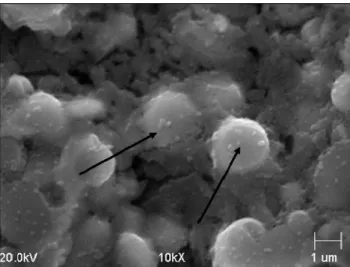
. The transient zone between the composite layer and casting coreFigure 8 shows the selected areas of a composite layer within which the clusters of carbide phases are visible (Fig. 8a). This effect is the result of a coagulation of the TiC particles in molten
alloy. The said process is distinctly visible in Figure 8b, where the neighbouring particles are joined together, forming oblong and spherical units. This phenomenon results in a spheroidisation of the TiC carbides produced by synthesis.
a)
b)
Fig. 8. The composite cast steel/TiC layer (a) with well visible regions of coagulated carbides (b)
The images in Figures 9-10 clearly shows the spheroidal shape of TiC carbides produced by SHS synthesis in the liquid. Closer look at the fracture shown in Figure 9 indicates the presence of strong forces of adhesion acting between the particle and matrix, as confirmed by the broken crystals of TiC. Their bonds with the matrix are so strong that the fracture is running through the crystal without impairing its contact with the matrix.
Fig. 9. The spheroidal shape of titanium carbides revealed on fracture
Fig. 10
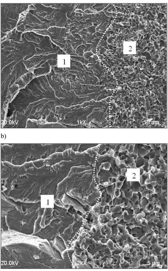
. The spheroidal shape of titanium carbides revealed on after deep etching with aqua regiaFigure 11 shows fractures of cast steel/TiC material. One can see the phase boundary present between the composite area containing TiC carbides and casting core. Region 1 marked in Figures 11a and 11b is the casting core area (carbon cast steel). It has the microstructure typical of brittle fracture. An opposite situation is observed in region 2 in Figures 11a and 11b, where the matrix shows all the characteristics typical of ductile fracture.
Table 1 shows the results of the Vickers hardness test carried out on a composite layer produced in casting. The results of the hardness measurements confirm the gradient character of the material. Compared with the hardness of the matrix, the hardness in the subsurface layer has increased by an average of 40% (double at a maximum). The discrepancy of the results compared in the table is due to a typical gradient distribution of the hardness values in the composite layer and in other parts of casting.
a)
b)
Fig. 11. The phase boundary present between the casting core (region 1) and composite area containing TiC carbides (region 2)
Table 1
Measurem
ent No.
Hardness of cast steel /TiC
layer [HV]
Matrix
hardness [HV]
1 700 565
2 771 580
3 834 610
4 865 -
5 889 -
6 1134 -
3. Discussion of results
It has been stated that the surface layer produced in cast steel was of a composite character, as confirmed by the presence of TiC carbides obtained in SHS synthesis. The thickness of this layer ranged from 550 to 1200µm (Fig. 3-4) and depended on the amount of substrates of the exothermic reaction applied on mould walls. The size of the TiC carbides produced by synthesis ranged from 0,5µm to 4µm, and in the case of clusters of the coagulated carbides, phases of even 20µm were observed (Fig. 8). Deep etching and fracture of the composite layer of the casting revealed a non-typical, spheroidal shape of the TiC particles (Fig. 9-10). Considering the conditions of alloy solidification and the low value of the heat transfer coefficient of a ceramic mould, it can be concluded that the crystals of titanium carbide were growing under the conditions of insufficient undercooling, hindering the formation of faceted crystals, typical of TiC. This effect can be the result of a local quasi thermodynamic equilibrium, which makes crystals growing in the liquid coagulate in an attempt to reach the minimum surface energy.
To check the utilisation properties of the obtained material, hardness was measured in both the composite layer and matrix. It has been stated that the hardness of the composite layer was from 700 to 1134 HV (Table 1), while matrix hardness assumed the values from 565 to 610HV. The obtained measurements indicate large differences, resulting from a variable TiC carbide content in the matrix. This is the reason why in subsurface layer, hardness exceeded the value of 1100 HV, making this layer twice as hard as a matrix. Figure 4 shows microstructure of the examined cast steel matrix (casting core). It is composed of martensite, bainite and residual austenite, which affect its high hardness comprised in the range of 565-610HV.
4. Conclusions
Within the framework of these studies, a technology was developed to manufacture the abrasion wear resistant composite layers in cast steel. The technology is based on the principle of the self-propagating high-temperature synthesis of titanium carbide, which takes place directly in the alloy melt. In the case under discussion, the process of the in situ synthesis ensures obtaining the structure of titanium carbides TiC in selected casting areas. Their presence in alloy matrix raises t Their presence in alloy matrix raises the hardness even twice he hardness even twice.
References
[1] B. Kieback, A. Neubrand, H. Riedel, Processing
Techniques for Functionally Graded Materials, Materials Science and Engineering A, 362A (2003) 81-105.
[2] A. Kawasami, R. Watanable, Concept and P/M Fabrication of Functionally Gradient Materiale, Ceramics International, 23 (1997) 73-83.
[3] B. Major, W. Mróz, T. Wierzchoń, W. Waldhauser, J. Lackner, R. Ebner, Surface and Coatings Technology, 180-181 (2004) 580-584.
[4] K.a. Khor, Y.W. Gu, Z.L. Dong, Plasma Spraying of
Functionally Graded Yttria Stabilized Zirconia/NiCoCrAlY Coating System Using Composite Powders, Journal of Thermal Spray Technology, 9 (2000) 245-249.
[5] J. Zhang, Y.Q. Wang, B.L. Zhou, X.Q. Wu, Journal
Materials Society Letter, 17 (1998) 1677-1679.
[6] G. Zimmermann, A. Schievenbusch, in W.A. Kaysser (Ed), Functionally Graded Materials 1998, Proceedings of the 5th
International Symposium on FGM 1998, Trans Tech Publications, Switzerland, 1999 533-538.
[7] E. Fraś, A. Janas, A. Kolbus, E. Olejnik, Matrix- particle Interphase boundaries of the selected in situ and ex situ Composites MMCs ,Archives of Foundry, 6 (18) 2006, 297-304 (in Polish).
[8] E. Fraś, A. Janas, A. Kolbus, E. Olejnik, Cast Ni3Al/MeC
(Me-W,Zr) Composites In Situ, Archives of Foundry, 6 (18) (2006), 317-324 (in Polish).