Numerical comparison between the thermo-structural
behavior of steel and partially encased steel and
concrete composite columns in fire
Comparação numérica entre o comportamento
termoestrutural de pilares de aço e mistos de aço e
concreto parcialmente revestidos em situação de incêndio
a Universidade de São Paulo, Departamento de Engenharia de Estruturas, Escola de Engenharia de São Carlos, São Carlos, SP, Brasil.
Received: 23 Aug 2017 • Accepted: 22 Jan 2018 • Available Online: 20 Jul 2018
Y. S. SIMÕES a
F. M. ROCHA a
J. MUNAIAR NETO a
Abstract
Resumo
The bare steel structural members have a low fire resistance. However, in steel and concrete composite members, the concrete encasement, besides the contribution to the stiffness of the whole system, reduces the amount of heat that reaches the steel profile, increasing the its fire resistance. The aim of this paper is to conduct a numerical study on the behavior of steel and steel and concrete composite columns in fire, in order to compare their performance based on the variation of parameters such as the stiffness of the surrounding structure, geometric imperfection and load ratio. It has been found that, in general, the intensity of the geometric imperfection and stiffness of the surrounding structure does not affect the fire resistance of steel and composite columns. However, the stiffness of the surrounding structure raised the maximum value of the restraining forces generate throughout the heating. Regarding the load ratio, when increased, the fire resistance and critical temperature decreased.
Keywords: steel and concrete composite columns, steel columns, numerical study, fire, fire resistence.
Os elementos construtivos de aço sem proteção possuem baixa resistência ao fogo. Apesar disso, nos elementos mistos de aço e concreto, o
revestimento de concreto, além da contribuição de rigidez para o sistema, reduz a quantidade de calor que chega ao elemento de aço
aumentan-do assim a sua resistência ao fogo. Diante disso, o artigo tem como objetivo realizar um estuaumentan-do numérico acerca aumentan-do comportamento de pilares
isolados de aço e mistos de aço e concreto em elevadas temperaturas, visando comparar o desempenho dos mesmos a partir da variação de parâmetros como rigidez da estrutura circundante, imperfeição geométrica inicial e fator de carga. Foi constatado que, em geral, a intensidade da
imperfeição geométrica e da rigidez da estrutura circundante não afeta a resistência ao fogo de pilares de aço. Entretanto, a rigidez da estrutura circundante elevou o valor máximo das forças de restrição geradas. Em relação ao nível de carga, quando aumentado, diminuiu o tempo e a temperatura críticos.
1. Introduction
Steel and concrete are the main materials used in civil
construc-tion. Regarding the fire action, steel has a poor behavior when not
protected, since it has a high thermal conductivity and it forms
pro-files which parts have reduced thicknesses. The sum of the factors
described leads to a faster section heating, also accelerating the
degradation of its mechanical properties (stiffness and tensile and
compressive strength).
The steel behavior concerning fire can be improved by applying to
it fire protection encasement or by associating it with other materi
-als that have a better performance at high temperatures. The high cost and the aesthetic interference that the protective materials
can cause in the structural element are some of the key problems
in the use of this solution.
Concrete encasement on steel profiles is a good option to be used
to ensure greater strength of the structural elements at room
tem-perature and also in a fire situation. By forming stronger structural
elements and by the lower thermal conductivity of the material,
concrete structures take longer to heat in comparison to the steel
structures. In view of the presented features, composite structures
are increasingly being used in the construction of multi-floor build
-ings. In this structural conception, concrete increases the structure
bearing capacity and acts as a steel profile encasement, protect
-ing it against fire and corrosion actions. Steel, on the other hand,
also improves concrete behavior at high temperatures, in order to
reduce the displacement effect and its cracking.
In Brazil, the subject is approached by the Brazilian Association of Technical Standards (ABNT) through the Brazilian Standard (NBR)
14323 [1] which basically follows the principles of European stan
-dards, EUROCODE 3 and 4 Part 1-2 [2, 3]. The standard script presents a simplified design method for isolated columns taking
into account only the degradation of the mechanical properties of
the materials with the temperature increase. However, according to Bubach [4], in real fire situations, in addition to the mentioned
reduction, the interaction between the structural element and the surrounding structure must be considered, which may compromise the application of the referenced method.
The columns are part of a global structure, so that they interact with the beams or slabs, which may be on top of them. Therefore,
during a fire, the column naturally tends to deform, but the rest
of the structure imposes thermal restraints on this deformation, which promotes the presence of additional stresses on the isolated
columns that can affect their stability, modifying the element fire
resistance [4].
There are two types of thermal restraints, the axial restraint, which imposes a certain effort to the longitudinal deformation of the column, causing the increase of its axial forces, and the rotational restraint,
responsible for partially obstructing the rotation at the column ends
and generating bending moments. The scientific community states that both restraints have opposite effects on the fire resistance of 4-face heated columns, so that the axial restraint acts in a way to
decrease it, and the rotational one increases it [1, 5, 7, 8, 9, 11]. Neves [5] carried out a detailed numerical study, using the ZWAN
computational code, regarding the surrounding structure influence,
the applied load eccentricity and the slenderness on the behavior of
steel columns in a fire situation. From the restraining forces behavior, the author defined the concept of steel columns fire resistance as the
moment when, after the internal forces increase, the column returns to the observed loading level prior to heating. This moment is called critical time and the temperature associated with it is called the critical
temperature. This concept will be used in the present work.
Aasen [6] presents an experimental analysis of steel columns in a fire situation, considering thermal restraints in their ends. The aim
of this work was to evaluate the influence of axial and rotational re
-straints on the fire resistance of these structural elements. Similarly,
Ali et al. [7] and Ali and O’Connor [8] developed an experimental pro -gram to study the parameters mentioned above, including load ratio
variation and structural element slenderness (only in the first study).
Neves et al. [9] created a numerical model, from the FINEFIRE
computational code, in order to determine a simplified methodol
-ogy capable of accounting for thermal restriction effect in determin
-ing the critical temperature value of steel columns that had been tested without restriction at their ends. Therefore, a parametric analysis was performed with the variation of the following
param-eters: cross-section, slenderness indexes and load ratio.
Correia and Rodrigues [10] proposed a new structure for experi
-mental tests of columns in a fire situation, so that the structural
element was inserted into a three-dimensional restraining frame capable of representing a real structural system. The study was based on the variation of the same parameters evaluated in Neves
et al. [9]. The following year, Correia et al. [11] used the experi -mental data of the developed tests and carried out a numerical
research with the purpose of proposing a simplified method to de
-termine the fire resistance of steel columns in a fire situation with
thermal deformation restrictions.
In the same research path, Bubach [4] analyzed the behavior of
steel columns with axial and rotational restraints, acting individual
-ly and simultaneous-ly, from a numerical modelling. Subsequent-ly, the numerical results were compared with those provided by the Brazilian standard ABNT NBR 14323 [1].
The presented studies reached similar conclusions, noting the
negative effect of the axial restriction and positive effect of the ro
-tational restriction in the fire resistance of the column. In addition,
it was possible to conclude that the increase in load ratio caused a sudden drop in the intensity of the generated constraining forces and the critical temperature. In relation to the slenderness, in
gen-eral, its increase resulted in the fire resistance reduction.
Most of the researches carried out worldwide refer to steel and concrete composite columns, just a few considered the partially encased columns.
Huang et al. [12] tested isolated partially encased columns
con-sidering only axial restriction (with varying levels) at the ends. The
authors concluded that their collapse occurred due to global
in-stability and that the axial restriction increased the compressive force, which reduced their fire resistance. Another phenomenon
that also helped in this decrease was the concrete displacement. The following year, these authors [13] developed another
numeri-cal modelling, this time, in order to evaluate the influence of the
applied load ratio on the composite column and the cross-section dimensions. The results indicate that, for high load ratios, sections
Correia and Rodrigues [14], using the same test structure present-ed in Correia and Rodrigues [10], testpresent-ed steel columns partially
encased with concrete, with axial and rotational constraints (differ
-ent intensities) at their ends subjected to high temperatures, also
varying the load ratio and column slenderness. The main finding,
in addition to those already described, was the increase in fire re
-sistance compared to steel columns.
Ellobody [15] performed a numerical study of partially encased fire-exposed columns changing the load ratios, axial stiffness,
cross-sectional dimensions and the aggregate type used in the concrete.
The study found that the composite columns without axial restraint showed a sudden collapse, unlike those with thermal restraint that presented in the “constraint force x time” graph, a softer drop. Han et al. [16, 17], through experimental tests and numerical anal -ysis, described the behavior of encased composite columns under
fire action. The first study [16] proposes a simplified method, based
on parametric analysis performed by numerical modelling, to
de-termine the columns fire resistance, while the second article [17] increased the knowledge regarding the post-fire behavior of these
structural elements.
The works presented above considered in its analysis the behavior
of isolated steel columns and steel and concrete composite
col-umns separately. Therefore, in order to identify the difference in
structural performance between these elements, a set of
numeri-cal analysis was developed to evaluate the benefits of concrete in a fire situation. Other analysis with the validated model were also developed, aiming at analyzing parameters such as the influence
of the axial restraint level, the applied load ratio and the intensity of the initial geometric imperfection in the fire resistance of steel and
steel and concrete composite columns.
2. Reference experimental model
The development of a consistent numerical modelling is based on
a detailed study of the experimental test used for its validation. To validate the numerical models, the results of the experiments
described in Rocha [18] and carried out in the Laboratory of
Test-ing Materials and Structures of the University of Coimbra were ad
-opted. This experimental work focused on the study of steel only
and steel and concrete composite columns embedded on walls, still, tests without walls were also performed.
The experimental program was defined in order to evaluate the following parameters: columns slenderness, wall thickness, profile position in relation to walls, influence of concrete acting in conjunc
-tion with steel profiles and load ratio. Considering the tests on iso
-lated and inserted-into-walls columns, a total of 12 prototypes were carried out at elevated temperatures. The numerical study that will be approached in this article used only the results for the isolated columns (no walls) of Rocha [18].
Highlighting the columns used in this work, the HEA 220 steel pro
-file with 2940 mm in height was used. As a boundary condition, square plates measuring 450 x 450 x 30 mm in thickness were
considered at the element ends, resulting in a column with a total height equal to 3000 mm. For the composite columns, concrete of
class C30/37 placed between the flanges was used. Besides, the
concrete was longitudinally reinforced with 20 mm diameter bars, CA50 type, as well as transversely with 8 mm diameter stirrups and 15cm spacing. The cross-sectional dimensions used are shown schematically in Figure 1a.
For carrying out the tests considering elevated temperatures, the cross-section load capacity was determined so that the column was loaded as a portion of this value. The load applied in relation to the column load capacity is called load ratio or level. This situation will represent the load on which a building column will be subjected in
case of fire. From the calculation methodologies provided by EU
-ROCODE 3 and 4 [2, 3], Table 1 shows the theoretical values used.
As regards the test procedures, the columns were initially loaded at a 30% load ratio of their strength capacity (Table 1), then they were inserted into a three-dimensional restraint system and then heated in a vertical electric furnace (Figure 1b). This furnace was a modular type, composed of three modules with individual power supply, two modules with 1 m in height and the other one with 0.5 m. Therefore, only 2.5 m from the column were heated. The furnace openings through which the column was to be tested were
thermally insulated with ceramic blankets to prevent heat loss to
the environment and to prevent the furnace from heating. Figures 2a and 2b show a schematic cross-sectional
representa-tion of each of the study field columns. It shows the posirepresenta-tions of the thermocouples located in the experimental tests, responsible for
measuring the temperature. They are presented by the terminol-ogy TX.Y, where X indicates the column section along its length be-ing studied, while Y indicates the measurement point numberbe-ing. It
is further noted that temperatures were measured in five sections,
as shown in Figure 2c. In spite of this, the results presentation and
Figure 1
a) Geometric characteristics of the cross-sections
of the studied columns; b) Test system (Rocha [18])
(a)
(b)
Table 1
Theoretical load capacity for the columns used
Profile type (kN)
HEA 220 – steel profile 1560 HEA 220 – composite column 2610
the validation of the proposed models will be done with reference to section 3 (central), since it presented the highest temperature among the others, and for that reason the greatest degradation of its mechanical properties.
3. Proposed numerical models
For the numerical modelling, the ABAQUS computational code
was used, which has the Finite Element Method as the basic for
-mulation for solving engineering problems, which in turn provides
a range of finite elements that can be used to build the models of
interest. After analysis of processing time, results and compatibility
between the different types of elements, shell elements were ad
-opted for the steel profile, solid element for the concrete and beam
element for the reinforcements.
Each of the developed numerical analysis consisted of three steps performed in sequence. The first one, called thermal analysis, is
responsible for determining the temperature range obtained in
the experimental test during the entire heating time. The second
one is the insertion of the initial geometric imperfections as a dis-placement in the middle of the column span. And in the last step, called thermo-structural analysis, the imperfect structural element is loaded and gradually receives the previously determined
ther-mal field aiming to represent the behavior of the actual column in a fire situation. In this step, the development of the axial forces and
displacements during the heating is analyzed.
Table 2 indicates the nomenclature adopted by the computational
code for the finite elements used in the thermal and thermo-struc
-tural modelling.
3.1 Boundary conditions and materials properties
ABAQUS adopts the principle of energy conservation to perform
its thermal analysis, using the thermal equilibrium equations.
Regarding the type of analysis, the transient analysis in which the thermal properties of the materials and the temperature distribu-tion vary over time is assumed in this research. The boundary conditions required to perform a thermal analysis refer to the heat transfer mechanisms.
For the convection and radiation study, the convection coefficients
(αc) for the first mechanism, as well as the material emissivity (ε)
and the Stefan-Boltzmann constant (5,67x10⁻⁸ W/m²K4) for the
second are inserted. Heat conduction is considered as part of the
numerical model of parameters related to the section material
it-self, such as density, thermal conductivity and specific heat. The
heating curves used for the model validation were those obtained
in the three furnace modules extracted from the experimental tests
presented in Rocha [18], since they were different from the stan
-dard fire curve of the International Organization for Stan-dardization (ISO) 834 [19] recommended for fire tests. The difference between
the curves obtained in the experimental tests and that correspond
-ing to ISO 834 [19] is shown in Figure 3. It is observed that the
maximum distinction between them occurs in the first 20 minutes,
with the largest variation found being equivalent to 200ºC, which
guarantees that the experimental curves are outside the tolerance
limit established by ISO 834 [19] for according to the referred stan-dard a divergence greater than 100°C between the heating and the
standard fire curves is not allowed after 10 minutes of exposure.
The determination of the values of the mentioned parameters was initially based on those provided by ABNT NBR 14323 [1], i.e.
Figure 2
Instrumentation of the experimental test: a) Steel column; b) Composite column; c) Indication of the
sections in which the temperatures were measured (Rocha [18])
(a)
(b)
(c)
Table 2
Finite element nomenclature used in thermal and
structural models
Structural element component
Finite element: thermal model
Finite element: structural model
Steel profile DS4 S4R Concrete C3D8 C3D8R Reinforcement DC1D2 T3D2
Figure 3
αc = 25W/m² ºC and ε = 0.7 for the surface formed by steel and
concrete. Nevertheless, during the comparison of the numerical
results with the experimental ones presented in Rocha [18], it was verified that a good compatibility was not obtained, hence
sensitivity tests for such parameters were necessary. Thus, the emissivity value was varied from 0.5 to 0.9 and subsequently, 0.8 was adopted as the emissivity for the steel and 0.7 for the concrete, since they gave more representative results. The
change in emissivity values is justifiable because the heating situation that is obtained in an electric furnace test is differ
-ent from that which will be verified in a real fire. In relation to the convection coefficient, the value provided by the standard
was reasonable.
Steel and concrete properties used in thermal and thermo-struc-tural modelling of the parametric analysis of this study, which were carried out after the model validation, followed the Brazilian stan-dards ABNT NBR 14323 [1] for steel and ABNT NBR 15200 [20] for
concrete, i.e. the convection and emissivity coefficients previously
mentioned (αc = 25W/m² ºC e ε = 0,7) were considered, as well as
the curve by ISO 834 [19] for heated columns.
Regarding the mechanical properties, the steel was modelled fol-lowing the von Mises yield criterion in conjunction with the voltage versus strain diagrams as a function of temperature presented
in ABNT NBR 14323 [1]. However, for the reinforcement of the
steel and concrete composite columns, the degradation of the mechanical properties with the temperature increase was not
considered, because in the experimental test the value of this
parameter was always lower or close to 400ºC, when the steel starts losing resistance. For the concrete, it was observed that by adopting the elastic properties for this material, the model was
sufficient to effectively represent the thermo-structural behavior
of the composite columns.
In the conception of the numerical models, the longitudinal and transverse reinforcements were considered through the embedded
reinforcements command, in order to allow the interaction between
concrete and reinforcements. For the steel and concrete surfaces union in the contact regions, the tie constraint function of “master-slave
surfaces” type was adopted, responsible for joining the degrees of
freedom between the nodes of the surfaces in contact, resulting in a situation of total interaction between the materials.
3.2 Numerical model representation
The proposed numerical models for steel and composite columns are shown in Figures 4a and 4b, respectively. As can be seen,
square plates were not considered, so that their final length was
equal to 2.94 m. It is also worth noting that the columns were rep-resented horizontally to facilitate visualization.
The numerical strategy adopted for the thermo-structural represen-tation of the columns consists of inserting a spring at the upper end of the element in order to simulate the three-dimensional restraint
structure of the experimental test. Neves [5] had already stated
that the structure reaction to the column heating can be compared
to the action of a spring, whose stiffness depends on the physical
and geometrical characteristics of the structure that surrounds the
tested element. Thus, the spring will receive the axial and rota
-tional stiffness of the restriction structure, and from a sensitivity test, values of 30 kN/mm for axial stiffness and 5000 kN.m/rad for rotational stiffness were defined.
Initially, reference nodes were created at the columns ends on which the degrees of freedom of the structural element ends were
coupled. In the lower part, the RP-1 node was created and at the upper part were created the RP-2 and RP-3 nodes that receive
degrees of freedom from the top of the column and represent the behavior of a spring.
The thermo-structural model development was performed in 2
phases. The first phase consisted of the column loading stage with 30% of its final load, in which the axial force in the RP-2 node was applied. Moreover, as a boundary condition, the RP-1 node was fixed as well as the displacements in the X and Y directions and the rotation around the Z axis in the RP-2 node represented in Figure
3, so that the other degrees of freedom could be unrestricted to
display themselves. In the RP-3 node, no boundary condition was
applied because during mechanical loading the upper end of the column is free to deform and the spring does not participate. The second phase represents the column heating step and is
based on the coupling between the thermal field, defined in the
previous analysis, and the deformations obtained by the column loading. Therefore, the numerical model temperatures were trans-ferred to this step, in order to simulate the structural element heat-ing. Furthermore, the spring participation at the upper end as a
Figure 4
Modelled columns: a) H220-ISO; b) H220-CONC-ISO
boundary condition for the RP-3 node was inserted so that it acts
by restricting the longitudinal deformations (Z axis) and the rota
-tions around the X and Y axes which in the previous step were free
to deform. The numerical models were processed until the moment
when the column, after presenting the axial force peak, returned to present the applied initial load, being this fire resistance criterion defined by Neves [5].
The numerical results validation process, by comparing to the
experimental results presented in Rocha [18], was divided in two
stages, which were applied to steel only and steel and concrete composite columns.
In the first step, thermal analysis was performed to compare if the
temperatures obtained numerically showed good compatibility with
those measured in the experimental tests.
The second step concerns the thermo-structural model validation,
using axial displacement and relative axial force as comparison
parameters between numerical and experimental results. The rela
-tive axial force is obtained by the relation between the axial force
at a given heating instant and the measurement before starting the heating, thereby resulting in a dimensionless magnitude. The use of force, in relative terms, facilitates the results discussion when comparing the steel and composite columns, since the load
ap-plied in each of these cases is different.
4. Results
In view of the modelling strategy, presented in the previous items, the thermal and thermo-structural model for the steel only and steel and concrete composite columns were validated through the tests presented in Rocha [18] and already described in item 2. After the validation, the models were used to perform a parametric
analysis considering the ISO 834 [19] standard fire curve and the
ABNT NBR 14323 [1] resulting emissivities, taking into account the influence of factors such as the intensity of the overall imperfection in the column, the loading level and axial restriction at the ends.
Validation and parametric analysis will be discussed throughout this section.
4.1 Numerical model validation
Starting with the thermal analysis results, the temperature
varia-tions, obtained numerically and experimentally, in the middle sec
-tion of the steel and composite columns, respectively, are present-ed in Figures 5a and 5b.
In the steel column case, only two reading points were used for
validation, one for the web profile (T3.1) and the other one for the top flange (T3.2). As the temperature in the section is practically uniform, there is only a small temperature difference between the web and the flange, since the web has higher temperatures due
to the greater slenderness and the contact area with the heat. As can be observed, the numerical temperatures are very close to the
experimental measurements.
In the composite column case, shown in Figure 4b, most of the
numerical results were well suited to the experimental ones, so that the difference between the curves was less than 10% in
most cases. However, only the temperatures obtained numeri
-cally for the T3.1 reading point, for the most part of the test,
result 100°C higher than those identified during the test. This is justified due the fact that the T3.1 temperature was obtained
inside the concrete, approximately 1 cm from the surface in con
-tact with the heat. Therefore, it cannot be said that the point at which the temperature was obtained numerically corresponds
exactly to the test reading point, possible cause for the results difference. Nevertheless, this difference does not compromise
Figure 5
Comparison between the temperatures obtained in the tests and numerically for the steel (a)
and composite (b) columns
the results, since in practical terms, the resistance loss is not high for a temperature increase of 100°C.
With the validated thermal model, we compared the thermo-struc-tural results of the modelled columns. Figures 6a and 6b show the
force and axial displacement development in the steel and steel
and concrete composite columns, respectively.
By analyzing, firstly, the relative axial forces result for the steel col -umns, it is observed that the numerical results are slightly higher
than the experimental ones, with the greatest difference found of 5%
between the curves in their rising part. In their descending part, the
difference increases to more than 10%, but this is acceptable, since
at that moment the column already has advanced local instability
which makes numerical representation difficult. In view of the fore
-going, since the force being developed in the structural element is greater in the numerical model (Figure 6a), as described previously, the displacement portion relative to compression is also higher,
which results in total axial displacement of the shortest column than that obtained experimentally, around 5% in the ascending segment
of the curve and 20%, in average, in the descending segment. Regarding the composite columns, satisfactory results were also
obtained, due to the approximation between the experimental and numerical results curves. By analyzing, primarily, the axial force, it
is noted that up to 50 minutes of fire, the numerical and experimen
-tal results are practically equal. From the 50-minute time point, the curves start to get distant, with the numerical model not represent-ing the sudden force drop at the end of the test. This behavior can be attributed to the fact that in the numerical model the mechanical
properties loss of the reinforcement by the fire action is not consid
-ered, so that the longitudinal bars can maintain their original
resis-tance during the entire heating time. In addition, the axial displace
-ments have a behavior quite similar to that observed in the forces. From Figure 5 and Figure 6, it can be concluded that the numerical model can satisfactorily represent the thermal and thermo-structur-al behavior of the steel and steel and concrete composite columns tested and with similar characteristics.
4.2 Parametric analysis
From the numerical model validated for the steel and steel and concrete composite columns, the same modelling strategy was
used to extend the analysis to other cases not addressed in the experimental program. As it is known in the scientific community,
factors such as the restraint imposed by the structure concerning
the column and the loading level significantly influence the dis -placements development and, consequently, the forces that de-velop during the heating.
It is also important to note that, although close, the heating curves
obtained in the experimental analysis and used in the validation
process do not match ISO 834 [19], recommended by ABNT NBR
14323 [1]. Besides, the coefficients used in the electric furnace test
to represent the radiation and convection phenomena also do not coincide with those recommended by ABNT NBR 14323 [1]. Thus, in this item, the parametric analysis performed to evaluate the structural behavior of the steel and composite columns,
com-posed of HEA 220 profile, is presented, considering the character
-istics foreseen in ABNT NBR 14323 [1], in which the standard fire
curve of ISO 834 [19] and emissivity factor equal to 0,7 were used, regardless of the material that constitutes the surface in contact with the heat. Among the parameters considered in the analysis,
the column loading level, the relative axial restriction level imposed
on the column and the global imperfection intensity in the middle of the span were varied.
As loading levels, values corresponding to 25%, 50% and 75% of the
column load capacity at room temperature were adopted. The axial
restraint level imposed on the column was considered relative, i.e., for the relation between the surrounding structure and the column
stiffnesses (375.1 kN/mm for the steel column and 1000 kN/mm for
the composite column) values of 5%, 10% and 30% were adopted. Considering that the steel and partially encased composite columns
have different load and stiffness capacities, the absolute value of the applied load and the surrounding structure stiffness were different
Figure 6
Comparison between the numerical and experimental results for the relative axial forces and
axial displacements in the steel column (a) and steel and concrete composite columns (b)
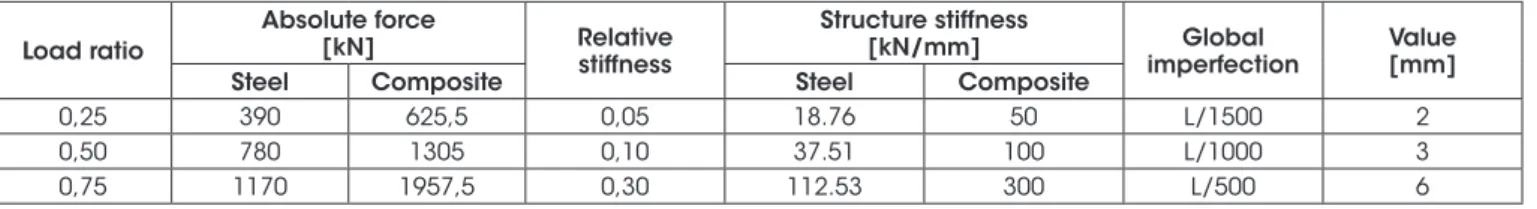
for each case, as indicated in Table 3, however loading levels and
relative stiffness fixed previously were respected. Finally, the last
parameter considered refers to the overall imperfection intensity of the column, values of L/1500, L/1000 and L/500 were chosen. In the followed items will be presented how each of the varied
pa-rameters should influence the thermo-structural behavior of the columns in a fire situation, analyzing mainly the contribution in the relative axial forces development during the heating.
4.2.1 Imperfection level influence
The first parameter chosen for the complementary analysis evalua -tion is the level of global geometric imperfec-tion adopted in the model.
Hence, the variations of the relative axial force as a function of the heat -ing time for the steel and composite columns, respectively, with 3 geo-metric imperfection levels adopted are presented in Figures 7a and 7b. Figure 7 shows the results for the models with load ratio of 75%
and relative stiffness of 30%, since for the other combinations the
behavior was similar.
Also, in Figure 7 it can be observed, that for the steel or composite columns, there is a behavior change when the geometric imperfec-tion is adopted or not in the model. In the steel column case, the
critical time (time at which the axial force returns to its initial value after the peak) decreased from 9.7 to 8.7 minutes, considering the
model without imperfection and the one with the imperfection of
L/1500, respectively. Still analyzing the steel column, increasing the imperfection from L/1500 (2 mm) to L/500 (6 mm), resulted in a decrease of only 0.2 minute at the critical time.
In the composite columns case, longer critical times were observed,
mainly due to the fact that the concrete encasement made it difficult to heat the central parts of the section. For example, the profile web,
which is protected by concrete, was heated mainly by conduction
that starts at the heated profile flange. It should also be taken into
account that the low thermal conductivity of the concrete causes it to
heat at a much lower rate than the steel profile, resulting always in
lower temperatures, especially in the innermost regions of the sec-tion. Owing to the fact that the concrete presents lower
tempera-tures, the profile reinforcement also has lower temperatures and
often does not present a decrease in its mechanical properties due
to the temperature effects. Consequently, all of these combined fac
-tors, in general, ensure longer fire-resistant time for the steel com
-posite columns partially encased with concrete.
Given that the imperfection level will not have a significant influ
-ence on the development of the relative axial forces, the other
analysis will be carried out always considering the models with global imperfection of L/1500.
4.2.2 Loading level influence
In the next step, the results are analyzed considering the influence
Table 3
Description of the parameters used in the parametric analysis
Load ratio
Absolute force
[kN] Relative
stiffness
Structure stiffness
[kN/mm] Global
imperfection
Value [mm]
Steel Composite Steel Composite
0,25 390 625,5 0,05 18.76 50 L/1500 2 0,50 780 1305 0,10 37.51 100 L/1000 3 0,75 1170 1957,5 0,30 112.53 300 L/500 6
Figure 7
Variation of the relative axial force for different values of geometric imperfection in models
with load ratio of 75% and relative stiffness of 30% in (a) steel and (b) composite columns
Figure 8
Influence of load level variation on the development of relative axial forces for steel and composite columns
(a)
(c)
(e)
(b)
(d)
of the loading level (LL) applied in the model. Figures 8a to 8f show
the evolution curves of the relative axial force for all processed models. In each one of them, a given level of relative axial stiffness is considered fixed, separately for steel and composite columns. Generally speaking, the higher the load ratio considered before the heating, the lower the relative axial force. This fact is confirmed
once it is possible for the column to increase its axial force con
-siderably until its load capacity, represented by the curve peak. Evaluating initially Figure 8a, which indicates the results for the
steel columns with 5% relative stiffness, the maximum relative axi
-al forces for the 25%, 50% and 75% load ratios were equ-al to 1.77, 1.30 and 1.14, respectively.
In addition, for the steel columns such peaks were observed at
different times, the lower the load ratio the more time was neces
-sary to reach the peak. This finding is justified, since the increase
of force occurs gradually with the increase of temperature and the
restriction of the thermal expansions. Thus, the lower the load ap
-plied to the column at the start of the heating, the more axial force
it will be able to absorb and, consequently, the more time it will required to reach its load capacity.
After the peak, the steel columns show a sharper drop than the composite ones. As for the peak values, the critical times ob -served are always larger the lower the load ratio used. Still in Figure 8a case, the critical times were 14, 10, 2 and 8 minutes for the loading factors of 25%, 50% and 75%, respectively. In section 4.2.4 will be presented a summary with all the critical times of the performed models.
Observing the behavior change of the curves with different load ratios, but with higher stiffness levels (Figure 8c and 8e), it is noted that the axial force behavior is similar to that discussed for Figure 7a. However, higher stiffness levels resulted in higher relative axial forces developed in the column, as can be seen from the difference
between the results of Figures 8a, 8c and 8e. More information
about the behavior for different stiffness levels will be commented
in the item 4.2.3.
For the composite columns shown in Figure 8b, 8d and 8f, a higher
critical temperature was identified when compared to the steel col
-umns, due to the fact that the concrete encasement decreased
the heating rate of the steel profile. Comparing Figures 8a and 8b,
it can be observed that for the case with 25% load ratio and 5%
relative stiffness, the critical time went from 14 minutes in the steel
column to 130 minutes in the composite column. In all cases it was observed that the composite column, when compared in a same
loading and stiffness level, presented critical time greater than the
steel one.
Another important feature to be observed in the composite
col-umns case is that, regardless of the load and stiffness level used, the time at which the peak force is reached was always the same. Besides, the post-peak behavior is much more ductile, with the axial force falling slowly. Finally, we look at the intensity of the max
-imum relative axial forces found in the composite column, which
are smaller than those of the steel columns, when compared to a
column with same stiffness and load ratio.
The fact that the relative axial forces for the composite columns
have lower values is related to the initial force intensities applied before the heating, which in turn are the divisors for the Relative
Axial Force calculation and are higher than in the steel columns
case. Hence, the absolute force acting on the column during heat
-ing may, in many cases, be higher in the composite column than in
the steel one, even having a lower relative axial force. In any case, the analysis by relative force is quite significant in order to compare the thermo-structural behavior between elements with different
characteristics, as well as to verify the amount of additional loading
that these elements will be subjected to during the fire.
4.2.3 Axial restraint level influence
In a similar way to what was done in item 4.2.2, in Figures 9a to 9f
are shown the variation of the relative axial force being kept a load
-ing level, separately for the steel and composite columns. Among the main considerations that may be mentioned, the most
notable is that, regardless of the stiffness level of the surrounding
structure, the column critical time will be practically the same when
considering the same loading level. The largest difference between
critical times was observed in the composite columns with load
ratio of 25% (Figure 9b), being approximately 20 minutes between
the models with higher and lower stiffness of the surrounding struc
-ture. In other cases, this difference was less than 1 minute. This finding can be observed in both steel and composite columns, as
can be seen in each of Figures 9a to 9f.
This is explained by the fact that the heating curve for all cases was the same. This way, by taking Figure 9d as an example, at 63 minutes (instant when the axial force returns to its initial value), the thermal field established in the sections, regardless of the stiffness
level considered in the spring, is the same. Therefore, the column
resistant capacity, which is directly affected by the mechanical
properties reduction by this temperature level, will be equal to the force acting on the section which, in turn, corresponds to the ap-plied load ratio.
Hence, what will be changed for each loading level will be the in
-stant that the heating generates a thermal field that reduces the
column resistant capacity to a value equal to the applied load. As the heating is the same in all cases, this instant is practically
coin-cident regardless of the stiffness considered in the spring.
With Figure 9 it is possible to note more clearly how the change in
the stiffness of the surrounding structure to the column will affect
the strength of the force generated in the column, being that the
greater the stiffness the larger the thermal expansion constraint, thus generating a bigger effort on the columns.
4.2.4 Results summary
As a way of summarizing the results presented throughout this
pa-per, for each of the models considered the time in which the peak value of the relative axial force is reached, the critical time and the
web and flange temperature at the instant of critical time are pre
-sented in Table 4. In that table, the results are pre-sented consider-ing the models with the least imperfection (L/1500), since for the
other values the results did not change significantly.
5. Conclusions
With the numerical models developed with the ABAQUS compu
Figure 9
Influence of the axial stiffness variation of the surrounding structure in the development of the relative
axial forces for the steel and composite columns
(a)
(c)
(e)
(b)
(d)
can represent well the thermal and thermo-structural behavior of
steel and steel and concrete composite columns considering the fire acting on all faces. However, the use of the values for the thermal
emissivity presented in ABNT NBR 14323 [1] did not present coher-ent results during the model validation process, being necessary to change it to represent the real test condition in an electric furnace. Regarding the behavior of the steel and composite columns
re-stricted to thermal elongation at their ends, when exposed to fire on all faces, it is possible to conclude that both exhibit a similar behavior, but with critical times of fire resistance quite different. In both cases, there is a gradual increase of the axial force to the peak instant, followed by the decrease of the force until the
moment when it returns to its initial test value. Nevertheless, the composite columns presented critical times up to 10 times
greater than the steel ones when considered the same stiffness
level and load ratio. The highest fire resistance of the compos
-ite columns is mainly due to the concrete encasement, which
reduces the web temperature of the steel profile, allowing it to
absorb the section stresses for longer. It should be noted that
the profile flanges presented higher temperatures at the test end
in the composite columns case.
Analyzing the results obtained by the parametric analysis, it can
conclude that the geometric imperfection did not significantly modi
-fy the thermo-structural behavior of the columns. However, the load ratio was the parameter that most influenced the fire resistance of
the column, so that the higher the load applied, the lower the
criti-cal time obtained. On the other hand, the maximum relative force
reached during the test was higher in cases where less load was applied, since the increase of force compared to the applied load is greater in these cases. Finally, the restraint level to deformations at
the ends does not interfere significantly in the column critical time, but in the maximum axial force reached during the test, so that the
higher the restriction level the greater the forces obtained.
6. Acknowledgments
The authors of this paper are grateful to the São Paulo Research Foundation (FAPESP), the National Council for Scientific and
Technological Development (CNPq), the Coordination for the Im
-provement of Higher Education Personnel (CAPES) and the De
-partment of Structural Engineering of São Carlos School of Engi
-neering/USP for the support directed to the accomplishment of the present work.
7. References
[1] ABNT. ASSOCIAÇÃO BRASILEIRA DE NORMAS TÉCNI
-CAS. Projeto de estruturas de aço e de estruturas mistas de aço e concreto de edifícios em situação de incêndio. - NBR
14323, Rio de Janeiro, 2013.
[2] EUROCODE. EUROPEAN COMMITTEE FOR STANDARD
-IZATION. Eurocode 3 - Design of Steel Structures. Part 1-2: General rules - Structural Fire Design. Brussels, 2005
[3] EUROCODE. EUROPEAN COMMITTEE FOR STANDARD
-IZATION. Eurocode 4 - Design of composite steel and con
-crete structures. Part 1-2: General rules- Structural Fire De
-sign. Brussels, 2005.
[4] BUBACH, C.R. Pilares de aço com restrição axial e rotacio
-nal em situação de incêndio, Espírito Santos, 2016, Disser
-tação (Mestrado em Engenharia de Estruturas) - Universi
-dade Federal do Espírito Santo, Vitória, 194 p.
[5] NEVES, I.C. The critical temperature of steel columns with
restrained thermal elongation. Fire Safety Journal, v. 24, n. 3, 1995; p. 211-227.
[6] AASEN, B. An experimental study on steel column behav
-iour at elevated temperatures. Division of Steel Structures, Norwegian Institute of Technology, University Trondheim,
Trondheim, Norway, 1985.
[7] ALI, F.A. et al. The effect of axial restraint on the fire resis -tance of steel columns. Journal of Constructional Steel Re-search, v. 46, 1998; p. 305-306.
[8] ALI, F.A. et al. The effect of axial restraint on the fire resis -tance of steel columns. Journal of Constructional Steel Re-search, v. 46, 1998; p. 305-306.
[9] NEVES, I.C.; VALENTE, J.C.; RODRIGUES, J.P.C. Thermal restraint and fire resistance of columns. Fire Safety Journal,
v. 37, n. 8, 2002; p. 753-771.
[10] CORREIA, A.J.P.M.; RODRIGUES, J.P.C. Fire resistance of
steel columns with restrained thermal elongation. Fire Safety Journal, v. 50, 2012; p. 1-11.
[11] CORREIA, A.J.P.M.; RODRIGUES, J.P.C.; GOMES, F.C.T. A simplified calculation method for fire design of steel columns
Table 4
Results summary of the parametric analysis models for steel and steel and concrete composite columns
Load ratio Relative stiffness Peak time [min] Critical time [min] Flange temperature [°C] Web temperature [°C]
Steel Composite Steel Composite Steel Composite Steel Composite
with restrained thermal elongation. Computers & Structures, v. 116, 2013; p. 20-34.
[12] HUANG, Z.F.; TAN, K.H.; PHNG, G.H. Axial restraint effects on the fire resistance of composite columns encasement
I-section steel. Journal of Constructional Steel Research, v. 63, n. 4, 2007; p. 437-447.
[13] HUANG, Z.F. et al. Fire resistance of composite columns with embedded I-section steel - Effects of section size and
load ratio. Journal of Constructional Steel Research, v. 64, n. 3, 2008; p. 312-325.
[14] CORREIA, A.J.P.M.; RODRIGUES, J.P.C. Fire resistance of
partially encased steel columns with restrained thermal elon-gation. Journal of Constructional Steel Research, v. 67, n. 4, 2011; p. 593-601.
[15] ELLOBODY, E. A consistent nonlinear approach for analys
-ing steel, cold-formed steel, stainless steel and composite
columns at ambient and fire conditions. Thin-Walled Struc
-tures, v. 68, 2013; p.1-17.
[16] HAN, L.H.; TAN, Q.H.; SONG, T.Y. Fire performance of steel
reinforced concrete columns. Journal of Structural Engineer
-ing, v. 141, n. 4, 2015; p. 04014128.
[17] HAN, L.H. et al. Performance of Steel-Reinforced Concrete
Column after Exposure to Fire: FEA Model and Experi
-ments. Journal of Structural Engineering, 2016; p. 04016055.
[18] ROCHA, F.M. Pilares de aço e misto de aço e concreto inse
-ridos em paredes em situação de incêndio, São Paulo, 2016, Tese (Doutorado em Engenharia de Estruturas) - Escola de Engenharia de São Carlos, Universidade de São Paulo, São
Carlos, 256 p.
[19] ISO. INTERNATIONAL STANDARD. Fire-resistance tests
- Elements of building construct - Part 1: General require
-ments. - ISO 834, 1999.
[20] ABNT. ASSOCIAÇÃO BRASILEIRA DE NORMAS TÉCNI
-CAS. Projeto de estruturas de concreto em situação de in