*Corresponding author, : [email protected]; +36 62 546 509;
*6724 Szeged, Mars tér 7., Hungary
*
SYNTHESIS OF SOME MECHANISMS
USING NATURAL COORDINATES
István Bíró*
University of Szeged – Faculty of Engineering Szeged, Hungary
DOI: 10.7906/indecs.12.3.5 Regular article
Received: 8 June 2014. Accepted: 15 July 2014.
ABSTRACT
The aim of this article is to demonstrate the kinematical synthesis of some mechanisms applied in agricultural machineries. The applied method based on the use of natural coordinates for this reason the method is simple and efficient.
The mechanical system is described by a set of geometric constraints. The design requirements are handled by a set of functional constraints. By the aid of objective function it can be obtained the values of design parameters of the mechanism.
Finally two characteristically examples are presented that illustrate the application of the method.
KEY WORDS
design parameters, kinematical synthesis, mechanisms, natural coordinates, optimization
CLASSIFICATION
256
INTRODUCTION
From the mid 1960s and early 1970s many programs for simulation of multibody systems were developed. These programs are not suitable directly for design because they were developed for kinematical and/or dynamical analysis of different planar and spatial mechanisms. During the investigation the engineer can study only the behavior of the mechanism. Before the investigation all geometrical and inertial characteristics of the multibody system should be defined.
Typical task for engineers is to design a new construction which fulfils certain requirements. From kinematical point of view in such cases the most important problem is to plan the main dimensions (design parameters) of the construction.
For this reason new design tools should be developed which can help the engineer during the design process.
There are some multibody simulation packages involved parametrical design modules for kinematical synthesis which are available for engineers. The efficiency of these program packages depends mainly on the experience of the engineer.
In the agricultural mechanical engineering enormous different type of mechanisms are applied. About 90 % of them can be approached as planar mechanism. The four-bar and the slider-crank mechanisms are the most frequently applied in agricultural machineries.
Kinematical synthesis of planar and spatial mechanisms and different optimization methods lead directly to a design that fulfils all expected requirements or at least is the optimum one considering some desired conditions. Generally the problems of kinematical synthesis are treated geometrically by the methods applied in this field. The tasks are the optimization of mechanisms from different point of views. The expected conditions can be complied by modifying of certain geometrical parameters such as lengths of the rigid bodies, position of no moveable kinematical joints, angles between axes of different joints, and so on.
Some program packages for optimal synthesis have been developed in recent decade. These are applied to many different types of planar and spatial mechanisms. Generally these programs are based on different types of numerical methods for optimization seeking the optimal solution with a minimum level of objective function.
In this paper to describe the mechanism natural coordinates will be used. As you will see the using of natural coordinates leads to a simple system of constraint equations. Therefore the applied method is also simple and efficient.
ABOUT THE KINEMATICAL SYNTHESIS
The kinematical synthesis of multibody systems is basically geometrical problem. About it much has been written by well-known authors [1-3] moreover many methods were developed. In the focus of the majority of this methods were the planar four-bar mechanism. Using these methods the results can be reached mainly on graphical way. Graphical methods in this field are limited to simple and planar mechanisms.
The problems of kinematical synthesis can be separated in three groups:
function generation synthesis;
path generation synthesis;
rigid body guidance synthesis.
257 In this paper the problem of path generation synthesis will be presented. This is a design of a planar four-bar mechanism. There is a specific point on the coupler which draws a trajectory that passes through a series of expected (predefined) points or at least goes as close to them as possible.
Rigid body guidance synthesis: in this case the aim is to create a four-bar mechanism in which a certain specific reference frame connected to the coupler passes through or goes as close as possible to a series of expected (predefined) positions.
THE NATURAL COORDINATES
The attribute “natural” means: coordinates which describe the mechanical system on the basis of the characteristics of the different types of kinematical joints. According to the opinion of Garcia de Jalon [4, 5] the natural coordinates lead to the simplest numerical treating of spatial mechanical systems because the geometrical definition of the mechanisms and the interpretation of the computed results are relative simple.
The creation of constraint equations is also simple because they are line or quadratic equations usually without trigonometrical expressions.
Using natural coordinates the position of a rigid body can be determined by the position of two or more points connecting to the body and the components of unit vector connecting to two or more bodies.
Since the points and unit vectors can be placed in the kinematical joints they can be divided along the kinematical chain. In this way the number of the coordinates of the mechanisms reduces and for this reason the number of the unknown variables in the equation system reduces as well. It follows of this that in such cases less mathematical operations are necessary during the design process.
Unda et al. have made a comparison between the using of natural coordinates and reference point coordinates [6]. The position of a rigid body can be determined by three coordinates of one point and three Euler-angles which are the reference point coordinates [7, 8].
Their investigation proved the above mentioned things. Applying natural coordinates
the number of coordinates of the mechanism reduces;
simpler constraint equations can be created;
and the computation is quicker.
On the basis of above mentioned the applying of the natural coordinates can be proposed.
DESIGN STEPS
The applied method is an improved version of the method presented by Jiménez et al. [9]. Although this method will be demonstrated by path generation problems of four-bar and slider-crank examples, it may be easily applicable to other planar and spatial movable structures. The following steps have to be taken into consideration in order to find the optimum solution for the investigated mechanism:
choose the topology of the structure. As a result of this step the engineer should know the number of rigid bodies with their topological description moreover the types of the kinematical joints,
determine the design parameters. They can be in general geometrical dimensions of the bodies, angles between axes of different kinematical joints, and so on,
define the design requirements,
create the geometrical and the functional constraint equations, and
258
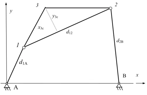
Fig 1. Sketch of the four-bar mechanism.
GEOMETRICAL AND FUNCTIONAL CONSTRAINT EQUATIONS
As an example let us consider the four-bar mechanism in Figure 1. Points A and B cannot be moved. The design parameters applying the markers in Figure 1 are the elements of the following vector: ] , , , ,
[d1A d12 d2B x3c y3c
T
b . (1)
The vector of dependent coordinates:
] , , , , ,
[x1 y1 x2 y2 x3 y3
T
q (2)
The geometrical constraint equations:
0 )
( )
(x1xA 2 y1yA 2d1A2 (3)
0 )
( )
(x1x2 2 y1y2 2d122 (4)
0 )
( )
(x2xB 2 y2yB 2d2B2 (5)
0 ) ( ) ( 12 1 2 3 12 1 2 3 1 3 d y y y d x x x x
x c c (6)
0 ) ( ) ( 12 1 2 3 12 1 2 3 1 3 d x x y d y y x y
y c c (7)
The functional constraint equations are created on the basis of specific requirements which should be complied. Point 3 on the coupler which draws a trajectory that passes through a series of predefined points or at least goes as close to them as possible. The set of design points (P1, P2, …, PN).
Every single design point corresponds to different values of the elements of vector q, for this reason vectors q1, q2, ..., qN are different. For the i-th position of point 3:
0 3ixPi
x (8)
0 3iyPi
y (9)
The constraint equations can be expressed in vector form in the following way: d2B
y
1
2
B x
259 0
b q,
Φ( ) (10)
As it can be seen in consequence of using of natural coordinates the constraint equations are really simple.
All constraint equations (geometrical and functional) for the i-th design point can be written as
0 b , q
Φi( i ) (11)
THE OBJECTIVE FUNCTION
At this section of the paper the objective function should be introduced. If the number of design points is less than 6, point 3 on the coupler of the four-bar mechanism can go exactly through the design points Pi. In other cases the design parameters have to be computed by minimizing
of the objective function. Since there is no exact solution for similar problems, for the optimal solution in the least square sense can be chosen. An objective function can be defined as
) , ( ) ( 2 1 ) , ,.., ( 1
1 q b Φ q ,b Φ q b
q i i i
T i i
N
N
(12)
The kinematical synthesis problem consists in minimizing the objective function Ψ with respect to vectors q and b.
EXAMPLE 1
A four-bar mechanism can be seen in Figure 1. Point 3 on the coupler should go through 5 predefined points. Their coordinates and coordinates of points A and B are given in Table 1. Design parameters (elements of vector b) have to be computed.
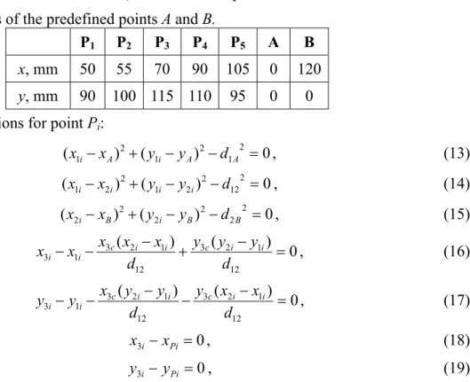
Table 1. Coordinates of the predefined points A and B.
P1 P2 P3 P4 P5 A B
x, mm 50 55 70 90 105 0 120
y, mm 90 100 115 110 95 0 0
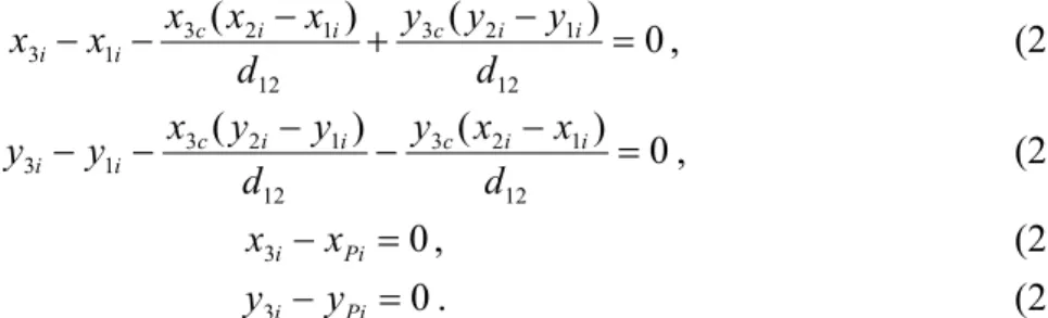
The constraint equations for point Pi:
0 )
( )
(x1ixA 2 y1iyA 2d1A2 , (13)
0 )
( )
(x1ix2i 2 y1iy2i 2d122 , (14)
0 )
( )
(x2ixB 2 y2iyB 2d2B2 , (15)
0 ) ( ) ( 12 1 2 3 12 1 2 3 1 3 d y y y d x x x x
x c i i c i i
i
i , (16)
0 ) ( ) ( 12 1 2 3 12 1 2 3 1 3 d x x y d y y x y
y c i i c i i
i
i , (17)
0 3i xPi
x , (18)
0 3i yPi
y , (19)
260
Table 2. Computed design parameters.
d1A d12 d2B x3c y3c
91,57 31,63 59,05 -13,20 48,99
EXAMPLE 2
A slider-crank mechanism can be seen in Figure 2. Point 3 on the coupler should go through 5 predefined points. Their coordinates and coordinates are given in Table 3. Design parameters (elements of vector b) have to be computed.
Fig 2. Sketch of the slider-crank mechanism.
Table 3. Coordinates of the predefined points.
P1 P2 P3 P4 P5
x, mm 81 162 192 162 86
y, mm 213 212 181 135 100
In this example xA=0 and yA design parameter. The design parameters applying the markers in
Figure 2 are the elements of the following vector:
] , , , ,
[yA d1A d12 x3c y3c
T
b (20)
The vector of dependent coordinates:
] , , , , ,
[x1 y1 x2 y2 x3 y3
T
q (21)
The constraint equations for point Pi:
0 )
( )
(x1ixA 2 y1iyA 2d1A2 , (22)
0 )
( )
(x1i x2i 2 y1iy2i 2 d122 , (23)
0 2i
y . (24)
y
1
2
x d1A
d12
x3c
y3c
A
3
261 0 ) ( ) ( 12 1 2 3 12 1 2 3 1 3 d y y y d x x x x
x c i i c i i
i
i , (25)
0 ) ( ) ( 12 1 2 3 12 1 2 3 1 3 d x x y d y y x y
y c i i c i i
i
i , (26)
0 3i xPi
x , (27)
0 3i yPi
y . (28)
for i = 1, 2, …, 5. The number of constraint equations and unknowns in this example also is 35. The obtained values of the design parameters can be seen in Table 4.
Table 4. Computed design parameters.
yA d1A d12 x3c y3c 70,64 92,08 286,30 69,21 114,04
CONCLUSIONS
A simple and general method for kinematical synthesis of planar mechanisms was demonstrated in this paper. The method is based on the use of natural coordinates for this reason the structure of the constraint equations is simple. The method is suitable for design of spatial multibody systems as well. According to my experience the most difficult part of the proposed method is the choice of the topology of the multibody system. If sometimes impossible to compute the design parameters one should choose another topology in order to find the proper solution [10].
In the agricultural mechanical engineering enormous mechanisms are applied. About 90 % of them can be treated as planar mechanism. The four-bar and the slider-crank mechanisms are the most frequently applied in agricultural machineries. The application of the proposed method has been demonstrated by solving two examples.
REFERENCES
[1] Angeles, J.: Spatial Kinematic Chains.
Springer Verlag, Berlin and Heidelberg, 1982,
[2] Erdman, A. and Sandor, G.: Analysis and Synthesis.
Prentice-Hall, 1984,
[3] Haug, E.J., ed.: Computer Aided Analysis and Optimization of Mechanical System Dynamics.
NATO ASI Series, Vol. 9, 1984,
[4] Garcia de Jalón, J. et al: Dynamic analysis of three-dimensional mechanism in natural coordinates.
ASME Design Engineering Technical Conference, Columbus, 1986,
[5] Garcia de Jalón, J. and Bayo, E.: Kinematic and Dynamic Simulation of Multibody Systems. The Real Time Challenge.
Mechanical Engineering Series, Springer-Verlag, New York, 1994,
[6] Unda, J. et al.: A comparative study on some different formulations of the dynamic equations of constrained multibody systems.
Journal of Mechanism 109(4), 466-474, 1987,
[7] Rodic, A.; Katic, D. and Mester, Gy.: Ambient Intelligent Robot-Sensor Networks for Environmental Surveillance and Remote Sensing.
Proceedings of the 7th International Symposium on Intelligent Systems and Informatics, SISY 2009, pp.39-44, Subotica, 2009,
262
[8] Mester, Gy.: Obstacle Avoidance and Velocity Control of Mobile Robots.
Proceedings of the 6th International Symposium on Intelligent Systems and Informatics – SISY 2008, pp.97-101, Subotica, 2008,
http://dx.doi.org/10.1109/SISY.2008.4664918,
[9] Jiménez, J.M. et al.: A simple and general method for kinematic synthesis of spatial mechanisms.
Mechanism and Machine Theory 32(3), 323-341, 1997,
[10] Bíró, I.: Analysis of spatial mechanisms applied in agricultural mechanical engineering. Ph.D. thesis.
Szent István University, Gödöllő, 1999.
SINTEZA MEHANIZAMA NA TEMELJU
PRIRODNIH KOORDINATA
I. Biró Sveučilište u Szegedu – Fakultet inženjerstva
Szeged, Madžarska
SAŽETAK
Cilj ovog rada je demonstracija kinematske sinteze nekih mehanizama koji se primjenjuju u poljoprivrednim strojevima. Primijenjena metoda temelji se na uporabi prirodnih koordinata i to je razlog njene jednostavnosti i učinkovitosti.
Mehanički sustavi opisani su skupom geometrijskih uvjeta. Zahtjevi dizajna oblikovani su u skup funkcionalnih uvjeta. Pomoću funkcije cilja mogu se dobiti iznosi parametara dizajna razmatranih mehanizama.
Naposljetku, dva karakteristična primjera ilustriraju primjenu ove metode.
KLJUČNE RIJEČI