Design of Framework for Logic Synthesis
Engine
Tribikram Pradhan 1, Pramod Kumar 2, Anil N S 3, Amit Bakshi 4
1
School of Information technology and Engineering, VIT University, Vellore – 632014, Tamilnadu, India 2
School of Computing Science and Engineering, VIT University, Vellore – 632014, Tamilnadu, India 3
Computer Science and Engineering, S. J. College of Engineering, Mysore, India
4
School of Electronics Engineering, VIT University, Vellore – 632014, Tamilnadu, India
1 [email protected] 3 [email protected] 2 [email protected] 4 [email protected]
Abstract- Logic synthesis is a novel architectural concept used for converting a high level description of logic circuit into optimized gate level description. The method ranges from transforming a RTL
description to producing an optimized netlist. Logic minimization plays an important role in optimization of logic synthesis. This optimization is done through the function minimization through different existing methods. The existing work on function minimization has resulted into many algorithms. In the proposed work, we form the basis for our synthesis engines vide detailed performance analysis and insight into the various minimization algorithms proposed erstwhile, and apply them on some real example circuit. We plan to propose our own algorithm as well for enhanced performance.
Keywords – Logic Minimization, Netlist, BDD
I. INTRODUCTION
A. Objective
In today’s VLSI design domain logic synthesis plays an important role as commercial production needs cost and time to be optimum. Any logic optimizer would target to reduce design time by analyzing the circuit’s requirement specifications and applying proper data structure and minimization methods, thus providing an optimal solution. But as time evolves, newer and smarter techniques have come into play. For our design of synthesis engine, currently we concentrate up to logic minimization part, leaving technology mapping and optimization. In this paper we would analyse some of the existing logic minimization methods (newer and older) which will provide the base for our future work.
B. Motivation
There are several logic synthesis engines currently available, for example MIS, MINI, ESPRESSO-MV, BDS etc. However, they use different methods for different stages of logic synthesis. And accordingly, these are highly dependent on the type and nature of functions. For some of such existing methods we have observed their behavior. For example, some uses heuristic approach for logic minimization, whereas others take exact approach. In heuristic approach neither exact prime implicants nor the cover is generated, rather it targets to find the minimal cover in least time. The exact minimization approach goes in detail to find the target.
C. Previous work and literature study
flexibility to map it into different technology libraries. The basic flow of logic synthesis process is as follows:
Phase-0
tool
works
here
Fig. 1. Logic synthesis flow and where we stand
Basically logic synthesis is a tool which is directly responsible to synthesis of both combinational and sequential RTL description. In to our system we input the behavioral description in high level language. Internally it generates a netlist which is un-optimized. Two level logic minimization occurs in logic synthesis method as we try to represent Boolean functions in terms of two-level AND, OR, NOT gates with minimal cost. There are two approaches to this problem: a) Exact logic minimization and (b) Heuristic logic minimization. Each of them uses different data structures. We implement both methods to analyse the choice of optimal data structure.
IV. DESIGN METHODOLOGY
As we have already defined our present proposed work in phase-0 concentrates on the first two phases of logic synthesis. Accordingly, it consists of the following phases:
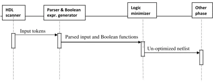
• HDL scanner
The operation of these modules can be understood from the following sequence diagram
Logic Other
HDL Parser & Boolean
minimizer phase
scanner expr. generator
Input tokens
Parsed input and Boolean functions
Un-optimized netlist
Fig 2. Sequence diagram of Phase-0 tool
The following section describes the methods followed to construct our tool.
A. Basic definitions and methodologies followed
Netlist: A netlist simply defines the circuit connection in terms of gates and other components. Ourtool will generate minimized netlist.
Boolean term:
A completely specified Boolean Function with n inputs and 1 output is defined as a mapping f:Bn B, where B = { 0, 1 }. Such a function can be specified by its onset ON (f) = {x, f(x) = 1}, offset OFF (f
) = {x, f(x) = 0}. If B = {0, 1,*} then we find an additional don’t care set called DC (f) = {x: f(x) = * } and the Boolean function is then incompletely specified.
A sum of products (SOP) denotes a completely specified Boolean function. Two level logic minimization actually finds a minimal cost SOP that covers (we say for two Boolean functions g and f one to cover some elements of f1. A SOP P is irredundant if there is no subset of P that covers f. So any minimum SOP of f is
irredundant, prime and finding such an SOP can be defined as a setcovering problem.
Let Z be a set, X a subset of Z, and Y a subset of 2Z . We say that y covers x when x∈ y. Let Cost be cost function that applies on subsets of Y. The set covering problem <X, Y > consists of finding a minimum cost subset S of Y such that any x of X is covered by some element y of S, i.e., Is the union of f’s iff f1⊆g1⊆f1*,
where f1 is the care set of f andf1* don’t care set . A product p is an implicants of f iff p ⊆f1*, if there is no other implicants that covers p then this implicants (PI) .a prime implicants is essential is the prime implicants (EPI).
V. IMPLEMENTATION DETAIL
Our proposed tool works in three phases. First, it takes an input from the user, which is the high level description of the circuit. Next it scans through it and generates the Boolean expression from it. Then it is fed to logic synthesis engine which gives detailed comparative analysis.
Thus it contains the following steps:
Step1. Compute the set of all prime implicants of f.
Step2. Consider the covering matrix with rows labeled by minterms of f and columns labelled by the prime implicants of f.
Step3. Using reduction technique finds the minimal PI set.
i) Take a minterm
ii) Consider it as a product
iii) Remove literals while preserving the implication
The method described above computes one PI at a time and thus limiting the number of PI.
The later discovered BDD method is far more powerful in this regard as it does not confine the number of Pis. The method works as follows:
Step1. Find the terminal nodes using Shannon’s co-factoring method Step2. Decompose the generated tree (OR decompose used)
Step3. Minimize the generated tree
B. Heuristic logic minimization method
In contrast to the exact logic minimization, the heuristic approach rather targets a near optimal solution in a very short time. Espresso-MV is such an algorithm.
C. Example
Input expression (given in minterms, for easy comprehension it is presented in terms of variables):
a’b’c’d’+a’b’c’d+a’b’cd’+ab’c’d’+ab’cd’+ab’cd+abcd’+abcd
The minimized SOP is : a’b’c’ + b’d’ + ac
Approach 2: Next it is minimized using BDD tree After minimization:
Here G = ac + ab’c’ and H = b’d’ F = G + H So the minimized output is F= ac + ab’c’ + b’d’
VI. OBSERVATIONS
1. Quine-McCluskey method does not always give the essential prime implicants set.
VII. PERFORMANCE ANALYSIS
It is observed that the runtime of Quine-McCluskey algorithm depends highly on the input size. As number of minterms N=2n depends on number of literal n, it grows exponentially with the increasing count of literal. Thus Quine-McCluskey is practically NP-Complete. On the other hand BDD generation is simple but the ordering of variable is a key to generate minimized functions. But finding the exact order for a particular function is Np Hard.
For a function with n input variable and 2n minterms the space needed to store and manipulate them in Quine-McCluskey method is
(n 2n + additional space for number of iteration)
Whereas, in BDD with same number of input variables the total space required is considerably less as the total number of node is 2n – 1, in worst case.
VIII. RESULTS AND DISCUSSIONS
Logic synthesis tool reduces the probability of error because human intervention is less. In this paper we have worked with several existing logic minimization algorithm which plays an important role in reducing design time. In the current scenario, it is found that BDD minimization method is more time and space efficient with respect to Quine-McCluskey. However, finding the exact order for a particular function is a key to this result.
IX. CONCLUSION AND FUTURE WORK
As our goal is to design an efficient logic synthesis engine (say logic optimizer), the current work provides a base for it. On the basis of the findings of this paper we shall continue working with this tool. In the current scenario, it is found that the BDD works well in terms of time and space. In the next phase, we shall work on the optimization of the intermediate netlist. However, we would also extend this to incorporate sequential and other complex circuit optimization.
REFERENCES
[1] Congguang Yang and Maciej Ciesielski ,”BDS A BDD based logic optimization system”
[2] Abdul A. Malik, Robert K. Brayton, A Richard Newton, Alberto Sangiovanni-Vincentelli, “A modified approach to two level logic minimization”
[3] Robert K. Brayton, Richard L Rudell, Alberto Sangiovanni-Vincentelli, Albert R. Wang,“MIS: A Multiple–Level logic optimization system”
[4] Richard L Rudell and Alberto Sangiovanni-Vincentelli, “Multiple-valued minimization forPLA optimization”
[5] Tsutomu Sasao, “Two level logic minimization”
[6] Samir Palnitkar, “Verilog HDL: A Guide to digital design and synthesis”
[7] M. Morris Mano, “Digital logic and computer design”
[8] Gary D. Hachtel, Fabio Somenzi, “Logic synthesis and verification algorithms”