O
ABSTRACT
Geometric and dimensional characteristics of
simulated curved canals prepared with proTaper
instruments
Renata de Castro MARTINS1, Maria Guiomar de Azevedo BAHIA2, Vicente Tadeu Lopes BUONO3
1-DDS, MSc, Postgraduate student, Department of Metallurgical and Materials Engineering, School of Engineering, Federal University of Minas Gerais, Belo Horizonte, MG, Brazil.
2-DDS, MSc, PhD, Full Professor, Department of Restoration Dentistry, Dental School, Federal University of Minas Gerais, Belo Horizonte, MG, Brazil. 3-BS, MSc, PhD, Full Professor, Department of Metallurgical and Materials Engineering, School of Engineering, Federal University of Minas Gerais, Belo Horizonte, MG, Brazil.
Correspondence address: Prof. Vicente T. L. Buono - Universidade Federal de Minas Gerais - Escola de Engenharia - Departamento de Engenharia Metalúrgica e de Materiais - Rua Espírito Santo, 35/206 - 30160-030 - Belo Horizonte, MG - Brasil - Phone: +55-31-3238-1859 - Fax: +55-31-3238-1815 - e-mail: [email protected]
Received: October 27, 2008 - Modification: May 21, 2009 - Accepted: August 11, 2009
bjective: This study identified which regions of ProTaper instruments work during curved root canal instrumentation. Material and methods: Twelve ProTaper instruments of each type, S1, S2, F1, and F2, were assessed morphometrically by measuring tip angle, tip length, tip diameter, length of each pitch along the cutting blades, and instrument diameter at each millimeter from the tip. Curved canals in resin blocks were explored with manual stainless steel files and prepared with ProTaper instruments until the apical end following four distinct sequences of instrumentation: S1; S1 and S2; S1, S2, and F1; S1, S2, F1, and F2. Image analysis was employed for measuring canal diameters. The diameters of the canals and diameters of the instruments were compared. Data were analyzed by one-way ANOVA and Tukey’s test. Results: No statistically significant difference was found between the canals and instrument diameters (p>0.05). The largest diameters in the end-point of the instrumented canals were obtained with F1 and F2 instruments and in the initial and middle thirds with S1 and S2 instruments. Conclusions: All instruments worked at the tip and along their cutting blades, being susceptible to fail by torsion, fatigue, or the combination of these two mechanisms.
Key words: Nickel-titanium. Endodontic instruments. Curved canals.
INTRODUCTION
Failure of NiTi rotary endodontic instruments takes place under two circumstances: torsional overload and flexural fatigue fracture14. Torsional fracture takes place when the tip or any part of the endodontic instrument is locked in a canal while its shaft continues to rotate. In this case, the elastic limit of the metal is exceeded and it undergoes plastic deformation followed by fracture4,14. The fatigue life of a NiTi rotary instrument is related to its dimensions and to
the degree in which it is flexed when placed in a curved root canal, with larger instrument diameters and greater flexures leading to a shorter expected life2,10,12.
increasingly larger tapers over the length of their cutting blades, allowing each instrument to engage, cut, and prepare a specific area of the canal. One of the benefits of a progressively tapered shaping instrument is that each instrument engages a smaller zone of dentin, reducing torsional loads, file fatigue, and potential for breakage. The finishing instruments F1, F2, and F3 have fixed tapers between D1 and D3 and decreasing tapers from D4 to D14. This design feature serves to improve flexibility and safety by reducing the potential for taper-locking13.
The purpose of the present study was to evaluate the geometric and dimensional characteristics of simulated curved root canals in resin blocks prepared with ProTaper instruments, aiming to identify which regions of these instruments work during curved root canal instrumentation. This identification was complemented by scanning electron microscopy (SEM) observation of the instruments before and after canal instrumentation. Considering that the only information regarding the dimensions of ProTaper instruments is the one given by the manufacturer, and that morphometric variations have been reported among other NiTi rotary instruments8,9, the dimensions of ProTaper instruments were also evaluated, in an attempt to correlate these measurements with the geometric and dimensional characteristics of the curved root canals prepared with them.
MATERIAL AND METHODS
Twelve ProTaper instruments of each type, S1, S2, F1, and F2, were used, totalizing 48 instruments, which were examined with a microscope (Mitutoyo TM 500, Tokyo, Japan) at
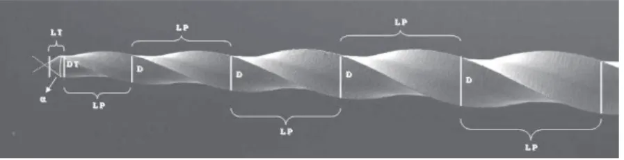
×30 magnification to evaluate: angle of tip (α), length of tip (LT), diameter of tip (DT), length of each pitch along the cutting blades (LP), and instrument diameter (D) at each millimeter from the tip (Figure 1), based on the ANSI/ADA Specification No. 1011. By instrument diameter, it is meant the largest distance between its extremities in the section perpendicular to the long axis. Tip angle is the angle between two imaginary lines tangent to the tip edges.
Twenty-one curved root canals in transparent resin blocks (Dentsply/Maillefer), with 16 mm in length, radius of curvature of 3.5 mm and an angle of 53º, measured according to the method described by Pruett, et al.12 (1997), were employed. The point of maximum flexure was at 3.5 mm from the apical end. The canals were instrumented by the same operator, being firstly explored with sizes 10 and 15 stainless steel K-files up to their full length. One explored canal served as control. During instrumentation, the canals were irrigated with water and no lubricant was employed. The other 20 canals were prepared with ProTaper instruments up to their full length following 4 distinct instrumentation sequences (5 canals for each sequence): S1; S1 and S2; S1, S2, and F1; S1, S2, F1, and F2. The instruments were operated at 300 rpm, using a slow-speed high-torque endodontic electric motor (TC Motor 3000; Nouvag, Goldach, Switzerland), with a 16:1 gear reduction hand piece (W&H 975; Dentalwerk, Bürmoos, Austria). Canal shaping followed the manufacturer’s recommendations and the end of the canal was reached only once, the instruments staying there for no longer than 1 second13. After each instrumentation sequence the instruments were inspected with the microscope at ×30 magnification to evaluate any
Figure 1- Morphometric parameters measured on the instruments according to ANSI/ADA Specification No. 101: tip angle (α), length of the tip (LT), diameter of the tip (DT); length of each pitch along the cutting blades (LP), and instrument
distortion on the cutting blades.
The canals were then photographed in a standardized manner, with a scale in millimeters, using a digital camera (Cyber-shot DSC - W1; Sony, Tokyo, Japan). The digital images were analyzed using Image-Pro Plus 6.0 image-analysis software (Media Cybernetics, Silver Spring, MD, USA). The canals had their diameters measured from the full end of the canal upwards to the initial third, in 1 mm intervals. Before and after instrumentation of the canals, the instruments were examined in a scanning electron microscope (JSM 6360; JEOL, Tokyo, Japan). The diameters of the canals and the instruments were analyzed statistically by one-way ANOVA at a significance level of 5%.
RESULTS
All ProTaper instruments examined presented a conical guide tip, with an average angle of 65.8 ± 2.25 degrees. The greatest variations in the tip angle were found in S1 (66.3 ± 2.91 degrees) and S2 (65.5 ± 2.68 degrees) instruments, while F1 (65.0 ± 1.49 degrees) and F2 (66.3 ± 1.52 degrees) instruments presented minor variations. Instruments S1 and S2 had 15 mm of active part, while F1 and F2 had 17 mm and 16 mm, respectively. The pitch length increased from the tip upwards in all instruments. The S1 and S2 instruments presented more spaced pitches along the cutting blades than the F1 and F2 instruments. S1, F2, and F3 instruments increased 45% on the first pitch length, and S2 and F1 instruments showed a smaller increase, around 35% and 23%, respectively. The increase in length from the second to the 8th pitches in S1 and S2 instruments was 8.5% and 12%, respectively. From the eighth to the last pitch, these instruments showed an increase of 21.5%. F1, F2, and F3 instruments presented an increase in length from the second to the last pitch of around 11, 12, and 10%, respectively.
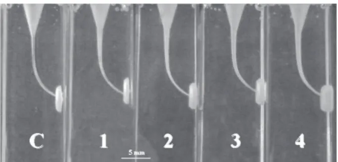
The final aspect of 5 curved root canals in resin blocks instrumented according to the four distinct sequences used in this study is shown in Figure 2. These sequences developed a funnel shaped form16, with smallest diameter at the
end-point and the widest diameter at the orifice. The use of resin blocks was chosen instead of extracted teeth because they allow direct visualization of the preparation shape in the clear resin. In addition, the use of canals with defined shapes in a standardized way favors the assessment and precision of the measurements. However, because of the difference in hardness between dentin and the resin blocks5, care should be taken in extrapolating the results to the clinical situation.
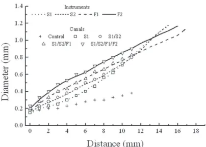
Figure 3 shows a plot of the mean diameters of the instruments measured at the tip and at each millimeter from the tip, as a function of tip distance, as well as the points representing the mean diameters of the canals measured from the end-point after each of the four sequences of instrumentation (standard deviations smaller than 5% of the mean diameter values). Figure 3 also shows that S1 instruments had a more gradual increase in diameter until D10. From D11 to D15, this increase in diameter was larger. In S2 instruments, the gradual increase in diameter goes until D10 and, from D11 to D15, the increase in diameter becomes larger. F1 and F2 instruments show the largest increase in diameter from D1 to D3. From D4 to the end of the active part, the increase in diameter in F1 and F2 becomes more gradual. These aspects can be observed in Figure 3 by the trajectory and inclination of the straight line corresponding to the ProTaper instruments. The close proximity of the lines (instrument diameters) and the data points (canal diameters) in Figure 3 indicates that the diameters obtained in the canals are closely
related to the dimensions of the last instrument used in each sequence. One-way ANOVA showed no statistically significant difference among the diameters of the canals or the instruments (p>0.05). It can also be observed that all instruments worked in the end-point, middle portion and orifice of the canals. The largest diameters next the end-point were produced with F1 and F2 instruments, while most of the shaping of the orifice and middle portion of the canals was carried out by S1 and S2 instruments.
During canal shaping, no instrument separation occurred and no distortion was noticed when the instruments were observed by optical
microscopy. However, all instruments inspected by SEM after canal shaping had microcracks, with a tendency of concentration of larger and wider cracks in the region D3 to D4, as illustrated in Figure 4 for an F1 instrument. In S1 and S2 instruments, finer microcracks, as well as signs of fretting, smoothed, or scratched surfaces were found until D7 (Figure 5).
DISCUSSION
International standards are provided to establish manufacturer’s guidelines followed to
Figure 3- Mean diameters of the instrument measured at the tip and at each millimeter from the tip, and mean diameters of the canals measured from the end-point after hand instrumentation (control), and each of the different sequences of instrumentation employed
Figure 4- Cracks (arrows) on the cutting edge at 3.5 mm from the tip of an F1 instrument after canal shaping
produce consistent and reliable dental products. ANSI/ADA Specification No.1011 does not strictly apply to ProTaper instruments because they show multiple tapers. However, it serves as a basis to measure geometric characteristics such as diameter at each millimeter from the tip, length of each pitch along the cutting blades, tip angle, tip length, and tip diameter. Since machining NiTi endodontic instruments is a complex procedure, morphometric variations among instruments of the same size have been reported8,9. In the present study, the largest variations in the tip angle were found in S1 and S2 instruments, probably because of the difficulty in machining instruments with small tip diameters. Despite of these variations, the tip angle of the instruments examined are in accordance with ANSI/ADA Specification No.1011.
The S1 and S2 instruments presented more spaced pitches along the cutting blades and this may improve flexibility. Increasing the pitch also reduces the helical angle, decreasing the torsional load and the tendency to taper-locking7. The less spaced pitches in the initial part of F1 and F2 instruments promote greater resistance in this region, allowing these instruments to safely shape the apical third of the canal, while the steeper increase in pitch length restores instrument flexibility away from the tip. The variations in instrument diameter reported here complement this design: the larger increase in diameter in S1 from D8 to D15 makes this instrument adequate to shape the coronal third of the canal, while in S2 the increase in diameter is larger from D5 to D10, since this instrument was developed to enlarge the middle third of the canal; the F1 and F2 instruments, developed to shape the apical third of the canal, show the largest increase in diameter until D3. All instruments analyzed presented tip diameter and dimensions along the cutting blades smaller than those reported by the manufacturer and the literature6,13.
The mechanical properties of polymers differ from those of dentin is a well known fact, but this study investigates the geometry and dimension of canals after shaping, irrespectively of the efforts made during shaping. The approach used would not be feasible in extracted teeth
because of lack of standardization on initial geometry and dimensions.
Comparing the canal diameters measured after each of the four instrumentation sequences employed with the control group diameters (Figure 3), it can be observed that all instruments worked close to their tips and along their cutting blades. Similar results were reported for ProFile instruments used in resin blocks15, but no such type of analysis could be found for ProTaper instruments. It can also be observed that the largest diameters next to the end-point were obtained with F1 and F2 instruments working until the full length, while most of the shaping of the orifice and middle portions was carried out by S1 and S2 instruments. However, S1 and S2 instruments also enlarge progressively the end third of the canals. In fact, Peng, et al.11 (2005) evaluated S1 instruments discarded after clinical use and found that these instruments fractured at a mean distance of 3.67 mm from their tips.
curvature of the canals associated with their largest diameter next to the tip3. In the present work, SEM analysis revealed a greater incidence of microcracks on the surface of these instruments close to the region of maximum canal curvature, that is, between 3 and 4 mm from their tip. Thus, it can be inferred that F1 and F2 instruments are subjected to torsional and flexural stresses in the apical third of the canals because of their largest diameter in this region and the curvature of the canals, being prone to fail by torsion, fatigue or by the combination of these two mechanisms.
CONCLUSIONS
The largest diameters in the end-point of the instrumented canals were obtained with F1 and F2 instruments, while most of the shaping in the initial and middle thirds was performed by S1 and S2 instruments. However, all instruments worked at the tip and along their cutting blades, being prone to fail by torsion, fatigue, or by the combination of these two mechanisms.
ACKNOWLEDGEMENTS
This work was partially supported by the Fundação de Amparo à Pesquisa do Estado de Minas Gerais (FAPEMIG), Belo Horizonte, MG, Brazil, Coordenação de Aperfeiçoamento de Pessoal de Nível Superior (CAPES), Brasília, DF, Brazil and Conselho Nacional de Desenvolvimento Científico e Tecnológico (CNPq), Brasília, DF, Brazil.
REFERENCES
1- American Dental Association. ANSI/ADA Specification No. 101.
Root canals instruments: general requirements. Chicago: The Instituition; 2001. 15p.
2- Bahia MGA, Buono VTL. Decrease in the fatigue resistance of nickel-titanium rotary instruments after clinical use in curved root canals. Oral Surg Oral Med Oral Pathol Oral Radiol Endod. 2005;100(2):249-55.
3- Berutti E, Negro AR, Lendini M, Pasqualini D. Influence of manual preflaring and torque on the failure rate of ProTaper rotary instruments. J Endod. 2004;30(4):228-30.
4- Blum JY, Machtou P, Micallef JP. Location of contact areas on rotary Profile instruments in relationship to the forces developed during mechanical preparation on extracted teeth. Int Endod J. 1999;32(2):108-14.
5- Calberson FL, Deroose CAJ, Hommez GM, De Moor RJ. Shaping ability of ProTaper nickel-titanium files in simulated resin root canals. Int Endod J. 2004;37(9):613-23.
6- Clauder T, Baumann MA. ProTaper NT system. Dent Clin North Am. 2004;48(1):87-111.
7- Diemer F, Calas P. Effect of pitch length on behavior of rotary triple helix root canal instruments. J Endod. 2004;30(10):716-8. 8- Marsicovetere ES, Burgess JO, Clement DJ, del Rio CE. Torsional testing of the Lightspeed instrument system. J Endod. 1996;22(12):681-94.
9- Martins RC, Bahia MGA, Buono VTL. Surface analysis of ProFile instruments by scanning electron microscopy and X-ray energy-dispersive spectroscopy: a preliminary study. Int Endod J. 2002;35(10):848-53.
10- Melo MCC, Bahia MGA, Buono VTL. Fatigue resistance of engine-driven rotary nickel-titanium endodontic instruments. J Endod. 2002;28:765-9.
11- Peng B, Shen Y, Cheung GSP, Xia TJ. Defects in ProTaper S1 instruments after clinical use: longitudinal examination. Int Endod J. 2005;38(8):550-7.
12- Pruett JP, Clement DJ, Carnes D Jr. Cyclic fatigue testing of nickel-titanium endodontic instruments. J Endod. 1997;23(2):77-85.
13- Ruddle CJ. The ProTaper endodontic system: geometries, features, and guidelines for use. Dent Today. 2001;20(10):60-7. 14- Sattapan B, Nervo GJ, Palamara JEA, Messer HH. Defects in rotary nickel-titanium files after clinical use. J Endod. 2000;26(3):161-5.
15- Schrader C, Peters OA. Analysis of torque and force with differently tapered rotary endodontic instruments in vitro. J Endod. 2005;31(2):120-3.