David José Pintão dos Santos Fontes Barbosa
Licenciado em Ciências da Engenharia Mecânica
Gas Tungsten Arc Welding
of
NiTi Shape Memory Alloy
Dissertação para obtenção do Grau de Mestre em
Engenharia Mecânica
Orientador: Doutora Rosa Maria Mendes Miranda,
Professora Associada com Agregação, Faculdade de
Ciências e Tecnologia da Universidade Nova de Lisboa
Co-orientador: Mestre João Pedro de Sousa Oliveira,
Faculdade de Ciências e Tecnologia da Universidade
Nova de Lisboa
Júri:
Presidente:
Prof. Doutor Jorge Joaquim Pamies Teixeira
Vogais:
Prof. Doutora Maria Luísa Coutinho Gomes de Almeida
Prof. Doutor Francisco Manuel Braz Fernandes
Prof. Doutora Rosa Maria Mendes Miranda
Gas Tungsten Arc Welding of Shape Memory Alloy NiTi
Copyright © 2014 David José Pintão dos Santos Fontes Barbosa
Faculdade Ciências e Tecnologia, Universidade Nova de Lisboa
AGRADECIMENTOS
Gostaria de expressar a minha gratidão a todos aqueles que me acompanharam ao longo deste período e aos que, direta ou indiretamente, estiveram envolvidos nesta investigação e sem os quais teria sido impossível torná-la realidade.
À minha orientadora, professora Rosa Miranda, primeiro pelo amável convite para este projeto, depois pela dedicação, disponibilidade, empenho e tempo despendido, consubstanciados no apoio que me foi dando ao longo da realização desta investigação. De salientar que foi também um prazer conviver, com a professora, nesta fase da minha vida académica, com quem aprendi muito, sendo de realçar que pertence ao grupo de docentes que mais me marcou ao longo do curso.
Ao meu co-orientador, Mestre João Oliveira que foi crucial, na fase inicial, para o arranque do trabalho orientando-me e, numa fase posterior, mostrou-se sempre disponível e interessado, mesmo à distância, ao arranjar tempo para me auxiliar no que quer que fosse necessário.
Ao professor Braz Fernandes, pelo interesse e pela disponibilizada que sempre demostrou para me auxiliar ao longo do desenvolvimento desta investigação. Ao professor Rui Silva pela ajuda prestada na realização dos ensaiso de SEM/EDS. Também gostaria de agradecer ao Pablo Vigarinho, pelo apoio que me deu aquando da realização de ensaios no CENIMAT.
Aos Srs. António Campos e Paulo Magalhães, com quem tive o prazer de conviver grande parte do período de implementação da fase experimental, pelo grande apoio e pela amizade demonstrada.
Aos professores Pamies Teixeira e Telmo Santos, pela cedência de “hardware”, sem o qual não poderia realizar a experimentação da investigação, como também pelo apoio que me foram dando ao longo da mesma. De salientar também que, a par da professora Rosa, pertencem ao grupo de docentes com quem tive o prazer e privilégio de aprender e os quais considero exemplos a seguir.
Aos meus colegas do laboratório de END, com quem privei alguns momentos, pela ajuda imprescindível na colocação do braço mecânico a funcionar, como também ao Renato Guerreiro e António Soares pela cedência das suas impressoras 3D para produzir as peças do "trigger". Referir a A. J. MALTEZ - SOCIEDADE METALÚRGICA, LDA, pela disponibilidade e alteração do aparelho para avaliação do efeito de memória de forma.
Aos meus colegas de turma - "Geração 09" - porque me acompanharam ao longo de todo o percurso académico e aos que entretanto chegaram nos anos seguintes, afilhados e caloiros e que de certa forma me marcaram e em parte me ajudaram a definir quem sou. Os importantes sabem quem são.
Aos meus grandes amigos do NAve- Associação Nova Aventura, com quem vivi grandes momentos e aventuras e que desde cedo estiveram presentes dando sempre apoio.
Às famílias Lamelas, Souto, Leiria, Paradela e Corte-Real por me terem acolhido e feito sentir como da casa e por todo o apoio que me foram dando ao longo deste período.
Às 3 gerações do grupo "Parolos", por serem simplesmente quem são. De realçar a minha madrinha, Conceição Ferreira, por estar sempre presente.
À Ana Rodrigo, pela amizade que sempre demonstrou como também por todo o apoio dado nesta fase final.
Ao Alexandre Manuel Costa, por toda a amizade demonstrada e por todos estes anos de convivência, sem dúvida um amigo para a vida. À sua família também, pela forma hospitaleira e amiga como sempre me recebeu.
Aos meus amigos de sempre, os meus irmãos Ivo Carrilho e Rudy Ribeiras e às suas famílias, que sempre estiveram e que sei que continuarão sempre presentes.
À Titi, à Irene e aos meus primos Clotilde e António pelo carinho, atenção e dedicação que demonstram e por garantirem que está sempre tudo bem.
Aos meus tios e primos, por terem estado sempre presentes e por me fazerem sentir em casa.
ACKNOWLEDGEMENTS
I`d like to express my gratitude to all those who accompanied me during the time I was doing this project and to whom, direct or indirectly, were involved on this investigation and without them I was unable to come this true.
To my assigned advisor, teacher Rosa Miranda, first of all by her kind invitation to perform this project, afterwards by her dedication, time and commitment, embodied on the support she gave to me during this investigation. It should be noted that was also my pleasure to spend time with my assigned advisor on this stage of my academic life, with whom I learned too much, being one of the teachers who I will never forget.
To my assistant advisor, Master João Oliveira who was crucial at beginning of my thesis, guiding me and afterwards, even from far away, being always available and interested to help me in what was needed.
To professor Braz Fernandes, by his concern and availability always showed to help me during my investigation. To professor Rui Silva for the help given during SEM/EDS measurements. Also to thank Paulo Vigarinho for his support with the test procedures at CENIMAT.
To Mr. António Campos and Mr. Paulo Magalhães, which whom I had the pleasure to be with during large period of the experimental phase of implementation of this project, by their support and friendship.
To my teachers Pamies Teixeira and Telmo Santos, who provide me the necessary hardware to perform my investigation, as for their support during the investigation. To be noted that, in line with teacher Rosa, they belong to the group of teachers that was my pleasure and privilege to have learned and I consider examples to follow.
To Omnidea, for lending me TIG welding machine, essential to develop this thesis.
To my classmates - “Class of 2009” – as we stood side by side during our academic journey and those who arrived during followed years, referrals and freshmen's that on a certain way marked and partially allowed me to define who I am. The key colleagues know who they are.
To my good friends of Nave – Associação Nova Aventura, with whom I lived big moments and adventures and earlier were present with their support.
To Lamelas, Souto, Leiria, Paradela and Corte-Real families, because of their strong support that given during this period and allowing me to became part of their family.
To the 3 generation of “Parolos” Group, as they are just as they are. Highlighting my Godmother, Conceição Ferreira, for allways being present.
To Ana Rodrigo, for her friendship always showed as for her support during this final stage.
To Alexandre Manuel Costa, for all his friendship and for all those years of conviviality. With no doubt a friend for life. Also to his family, by their hospitality and friendly welcome they received me at their home.
To my forever friends/brothers Ivo Carrilho and Rudy Ribeiras and their families, always present and as I know they will keep their presence.
To Titi, to Irene and to my cousins Clotilde and António for their affection, attention and for making sure that everything was always all right.
To my uncles, aunts and cousins, for always being present and for making me feel at home.
Mamani, Bhava! Kanimambo!
ABSTRACT
Shape memory alloys are characterized by the ability of recovering their initial shape after being deformed and by superelasticity. Since the discovery of these alloys, a new field of interest emerged not only for the scientific community but also to many industries. However, these alloys present poor machinability which constitute a constrain in the design of complex components for new applications. Thus, the demand for joining techniques able to join these alloys without compromising their properties became of great importance to enlarge the complexity of existing applications. Literature shows that these alloys are joined mainly using laser welding.
In the present study, similar NiTi butt joints, were produced using TIG welding. The welds were performed in 1.5 mm thick plates across the rolling direction. A special fixture and gas assist device was designed and manufactured. Also a robot arm was adapted to accommodate the welding torch to assure the repeatability of the welding parameters. Welds were successfully achieved without macroscopic defects, such as pores and distortions. Very superficial oxidation was seen on the top surface due to insufficient shielding gas flow on the weld face. The welded joints were mechanically tested and structurally characterized. Testing methods were used to evaluate macro and microstructure, as well as the phase transformation temperatures, the mechanical single and cyclic behaviour and the shape recovery ability. Differential Scanning Calorimetry (DSC), Scanning Electron Microscopy (SEM), Energy Dispersive Spectroscopy (EDS), microhardness measurements were techniques also used to evaluate the welded joints.
A depletion in Ni in the fusion zone was seen, as well as a shift in Ms temperature. For
KEY-WORDS
Shape Memory Alloys
NiTi
Welding
TIG
Shape Memory Effect
RESUMO
As ligas com memória de forma são ligas metálicas caracterizadas pela capacidade de recuperar a forma mesmo depois de serem deformadas e pela superelasticidade. Desde a sua descoberta este tipo de liga despertou o interesse da comunidade científica e de várias indústrias. Contudo, estas ligas são de difícil processamento, sendo um impedimento ao desenvolvimento e de novas aplicações requerendo formas mais complexas. Assim, tem-se investigado técnicas de ligação capazes de unir estas ligas sem comprometer as suas propriedades. Na literatura, estas ligas são unidas maioritariamente por soldadura laser.
No presente trabalho, foram produzidas juntas similares topo a topo de chapas de NiTi, utilizando o processo de soldadura TIG - Tungsten Inert Gas. As juntas foram feitas perpendicularmente à direção de laminagem e utilizaram-se chapas com 1,5 mm de espessura. Foi desenvolvido um sistema de fixação e de proteção gasosa para produzir as juntas soldadas e adaptado um braço mecânico para acomodar a tocha de soldadura por forma a garantir a repetibilidade do processo. Posteriormente, as juntas soldadas foram testadas mecanicamente através de testes de tração uniaxial, ciclagens e estudos do efeito de memória de forma; e caracterizadas estruturalmente com técnicas de análise como: a Microscopia Eletrónica de Varrimento (SEM), Energy Dispersive Spectroscopy (EDS), Microdurezas, Calorimetria Diferencial de Varrimento (DSC) e Difração de Raios-X (DRX).
Verificou-se uma diminuição da percentagem atómica de Ni na zona fundida bem como uma alteração da temperatura Ms. Para valores de deformação de 4% a deformação
PALAVRAS-CHAVE
Ligas com memória de forma
NiTi
Soldadura TIG
Efeito de Memória de Forma
CONTENTS
AGRADECIMENTOS ... v
Acknowledgements ... vii
ABSTRACT ... xi
KEY-WORDS ... xii
RESUMO ... xiii
PALAVRAS-CHAVE ... xiv
LIST OF FIGURES ... xix
LIST OF TABLES ... xxi
1
- INTRODUCTION ... 1
1.1
- Motivation ... 1
1.2
- Objectives ... 2
1.3
- Thesis structure ... 2
2
- WELDING SHAPE MEMORY ALLOYS ... 3
2.1
- Shape Memory Alloys - SMAs ... 3
2.2
- Characterization of SMAs ... 4
2.3
- Welding processes of Shape Memory Alloys ... 11
2.3.1
- Gas Tungsten Arc Welding - GTAW ... 11
2.3.2
- Laser Welding ... 14
2.4
- NiTi Similar Joints ... 15
2.5
- Applications ... 16
2.5.1
- Aerospace Applications ... 17
2.5.2
- Medical Applications ... 19
2.5.3
- Transportation Applications ... 21
2.5.4
- Other Applications ... 21
2.6
Summary ... 22
3.1
- Positioning Device ... 23
3.2
- Trigger Device ... 25
3.3
- Adapted Equipment ... 25
3.3.1
Moving Table ... 25
3.3.1.1
Testing Device For Shape Memory Effect Evaluation ... 26
4
- Experimental Procedure ... 29
4.1
- Materials... 30
4.2
- Welding Equipment ... 31
4.3
- Experimental Approach ... 32
4.3.1
- Butt joints ... 32
Samples Preparation For Testing ... 32
4.3.2
- Testing Methods ... 33
- Microstructure Observations ... 33
- Differential Scanning Calorimetry - DSC ... 34
- X-Ray Diffraction Analysis - XDR ... 34
- Microhardness Measurements ... 34
- Mechanical Tests ... 34
Uniaxial Tensile Testing ... 34
Cycling Tests ... 35
- Shape Memory Effect - SME ... 35
5
- Results and discussion ... 37
5.1
- Macroscopic observations ... 38
5.2
- Micro Observations ... 39
5.2.1
Microscope Observations ... 39
5.2.2
Scanning Electron Microscopy - SEM/EDS ... 40
5.3
- Differential Scanning Calorimetry measurements - DSC ... 41
5.4
- Microhardness Measurements ... 43
5.6
- Mechanical Tests ... 45
5.6.1
- Tensile Tests ... 45
5.6.2
- Cycling Behavior ... 46
- Cycling Tests ... 46
- Accumulated Irrecoverable Strain ... 49
5.7
- Shape Memory Effect Evaluation ... 51
6
- Conclusions and Further Work ... 53
LIST OF FIGURES
Figure 2.1 - σ-ε diagram. (0 - 5) martensitic deformation, heat recovery until austenitic
domain (SME); (5 – 10) superelastic deformation of austenite [5] . ... 4
Figure 2.2- Cristal structure of: a)B2 austenite; b) B19 Martensite (R-phase); c) B19' Martensite [7]. ... 5
Figure 2.3 - Temperature-induced phase transformation of a SMA without mechanical loading [8]. ... 6
Figure 2.4 - Schema showing the transition from twinned to detwinned martensite at constant temperature[8]. ... 6
Figure 2.5 - Schema of the Shape Memory Effect for a Shape Memory Alloy [8]. ... 7
Figure 2.6 - Temperature-induced phase transformation in the presence of applied load [8]. ... 8
Figure 2.7 - A superelastic loading path [8]. ... 8
Figure 2.8 - Stress-strain curve of conventional vs. superelastic alloys [9]. ... 9
Figure 2.9- Representation of lattice changes in stainless steel and in a superalloy [4]. 9 Figure 2.10- Ni-Ti phase diagram [10]. ... 10
Figure 2.11- Variation of transformation temperature with Ni content for binary Ni-Ti alloys [7]. ... 11
Figure 2.12- Autogenous Gas Tungsten Arc Welding (GTAW) process representation (Adapted from[12]). ... 12
Figure 2.13- Laser welding modes: a) "keyhole" and b) Conduction [14]. ... 15
Figure 2.14 - Relation between heat input and the weld bead face and root width. Adapted from [1]. ... 16
Figure 2.15 - Variable geometry chevron [8]... 17
Figure 2.16 - SMA hinges. Folded and deployed configuration [8]. ... 18
Figure 2.17 - Orthodontic applications of NiTi SMA: a) NiTi braces; b) schematic of a NiTi drill used for root canal surgery [8]. ... 19
Figure 2.18 - Cardiovascular applications: a) Simon's filter in deployed configuration; b) Self-expanding NiTi stent [8]. ... 20
Figure 3.1- a) Top view of the base - central canal and position rulers mounted; b) perspective view of base with position rulers mounted. ... 24
Figure 3.2- Welding chamber. ... 24
Figure 3.3 - Trigger device. ... 25
Figure 3.5 - Robot arm control program interface. ... 26
Figure 3.6- Device used for shape memory effect testing. ... 27
Figure 3.7 - Shape Memory Effect device after modifications. ... 27
Figure 4.1- TELWIN, TECHNOLOGY TIG 182 AC/DC-HF/LIFT. ... 31
Figure 4.2 - Specimens extracted from welded samples. ... 33
Figure 4.3 - Schema of pure bending [20]. ... 36
Figure 4.4 - Bending section [20]. ... 36
Figure 5.1 - Aspect of similar NiTi butt weld joints: a) sample #1.1; b) sample 1.2 and c) sample 1.3. ... 38
Figure 5.2 - Specimen microstructure visualization. ... 39
Figure 5.3 - Microstructure of: a) HAZ; b) Transition HAZ/FZ c) FZ. ... 39
Figure 5.4 - EDS results from Base Material... 40
Figure 5.5 - EDS results from Fusion Zone ... 40
Figure 5.6 - Vapour pressure as a function of temperature for Ni and Ti (Adapted from [6]). ... 41
Figure 5.7 - DSC measurements of the base material and molten material for determination of the transformation temperatures. ... 42
Figure 5.8 - Vickers Microhardness profiles made on specimen #1.3.2. ... 43
Figure 5.9 - Microhardness measurements in the cross section of the sample along weld top and root. ... 43
Figure 5.10 - XRD measurements of BM. ... 44
Figure 5.11 - XRD measurements of FZ. ... 44
Figure 5.12 - Tensile test performed on Base Material and specimens #1.2.3 and #1.3.4. ... 45
Figure 5.13 - Cycling test up to 4% elongation. ... 47
Figure 5.14 - Cycling test up to 6% elongation. ... 47
Figure 5.15 - Cycling test up to 8% elongation. ... 48
Figure 5.16 - Cycling test up to 12% elongation... 48
Figure 5.17- Evolution of the accumulated irrecoverable strain for specimen cycled at 4%. ... 49
Figure 5.18 - Evolution of the accumulated irrecoverable strain for specimen cycled at 6%. ... 50
Figure 5.19 - Evolution of the accumulated irrecoverable strain for specimen cycled at 12% ... 50
LIST OF TABLES
Table 2.1- Characteristics of current types for Gas Tungsten Arc Welding. ... 13
Table 4.1- Physical properties of NiTi SMA [19]. ... 30
Table 4.2- Mechanical properties of NiTi SMA [19]. ... 30
Table 4.3 - TELWIN, TECHNOLOGY TIG 182 AC/DC-HF/LIFT Technical Data [20]. ... 31
Table 4.4- Welding parameters chosen to weld the NiTi/NiTi butt joints specimens. .. 32
Table 4.5 - Specimens references and tests performed... 33
Table 4.6 - Uniaxial tensile test specimens. ... 35
Table 4.7 - Cycling test specimens ... 35
Table 5.1 - Atomic percentage of Ti and Ni on the base material and fusion zone. ... 41
Table 5.2- Transformation temperatures for base material and molten material. ... 42
Table 5.3 - Uniaxial Tensile test results. ... 46
Table 5.4 - Cycling Tests results. ... 46
1
- INTRODUCTION
Shape memory alloys (SMA) are known for the capacity to recover the initial shape after being deformed, when subjected to a specific thermal cycle, called Shape Memory Effect (SME). Since their discovery, in the 50's, applications using SMAs have increased significantly over the past decades and can be found in a wide variety of industrial sectors, from sensing and actuation applications, to more demanding industries as aerospace and biomedical. Although many materials can exhibit SME, just the ones that can recover the original shape are of commercial interest. Due to their properties, NiTi-are amongst the most used SMAs despite their poor machinability, which limits components design. Thus, joining SMA became a field of research to overcome these limitations and enlarge further applications.
1.1
- Motivation
1.2
- Objectives
The present study aimed at welding 1.5 mm thick NiTi plates in a butt joint configuration, using the TIG welding process and perform a structural and mechanical characterization of the joints.
For this, dedicated equipment was designed and manufactured to fix the plates. Welds were performed followed by a structural and mechanical characterization of the welded samples, using several techniques including Differential Scanning Calorimetry (DSC), Scanning Electron Microscopy (SEM), Energy Dispersive Spectroscopy (EDS), microhardness, uniaxial and cycling tensile tests and SME evaluation.
1.3
- Thesis structure
This thesis is structured in five chapters.
Chapter 1 includes a brief introduction contextualizing the study, motivation and objectives.
Chapter 2 provides the theoretical background of SMA behaviour for easier comprehension throughout the study as well as of the welding process.
Chapter 3 describes the equipment developed and the existing equipment altered.
Chapter 4 indicates the experimental procedure adopted, identifying the material used, the experimental methodology and the characterization techniques.
Chapter 5 presents and discusses the results of this investigation.
2
- WELDING SHAPE MEMORY ALLOYS
2.1
- Shape Memory Alloys - SMAs
As previously mentioned, SMA are metallic materials with the unique ability of recovering their initial shape even after being deformed. This type of alloys are characterized by the Shape Memory Effect, Superelastic Effect (SE), high damping capacity and magnetostriction. Such characteristic put SMAs in a particular class of advanced materials often called smart materials, together with other types of active materials, such as piezoelectric and magnetostrictive materials[2,3].
was a tribute to the first place where they were first discovered and studied, at Naval Ordnance Laboratory (NOL), in the beginning of the year 1960. Since then, SMAs have captured the interest of the scientific community and are still the most widely studied and applied [3].
With the technological advances, many difficulties related to SMA were exceeded, but research is still needed for these alloys to reach their full potential. Despite all disadvantages regarding costs, manufacturing, processing and/or joining SMA, there has been an increased use of SMA with success in many industrial sectors such as biomedical, automotive and aeronautical.
2.2
- Characterization of SMAs
SMA are materials characterized by SME and SE, unlike conventional metals and alloys. SME is characterized by the recovery of the initial shape by heating after being deformed, while SE is characterized by strain recovery when unloading [2]. Both effects are represented in Figure 2.1.
Figure 2.1 - σ-ε diagram. (0 - 5) martensitic deformation, heat recovery until austenitic domain (SME); (5 – 10) superelastic deformation of austenite [5] .
martensite has a monoclinic structure (B19'), the transformation from austenite to martensite can occur either in a one-step or by a two-step mode, depending on composition and thermal or thermomechanical treatments. On the two-step mode (represented in Figure 2.2), a third phase appear between austenite and martensite, called R-phase, that has a trigonal structure [3,7].
Figure 2.2- Cristal structure of: a)B2 austenite; b) B19 Martensite (R-phase); c) B19' Martensite [7].
There are two cristalgraphic forms of martensite: twinned martensite (Mt) and
detwinned martensit (Md). In the first opposite shears from opposite variants cancel, and
the microscopic shape of the crystal is preserved by forming a self-accommodating structure; in detwinned martensite a particular variant is dominant and as a consequence, the shape is not preserved. Variant is the denomination given to the orientation direction of each martensite crystal formed during the martensitic transformation [1,6,8].
In the austenitic phase, upon cooling and without any stress induced, the crystal structure changes to martensite. This transition is called forward or direct transformation. It occurs due to the formation of several martensitic variants, wich can be up to 24 in NiTi, which is arranged in such way, that results in twinned martensite. If afterwards the temperature rises, the opposite transformation occurs, and martensite transforms into austenite in a reverse transformation [1,6,8].
Figure 2.3 - Temperature-induced phase transformation of a SMA without mechanical loading [8].
As shown in Figure 2.3, associated with the phase transformations, there are four characteristic temperatures. During forward transformation, the austenite begins to transform to twinned martensite at the matensitic start temperature, Ms, and the
transformation will be finished at martensitic finish temperature, Mf. Upon reverse
transformation, there is austenitic start temperature, As, and austenitic finish temperature,
Af, when the transformation is fully completed.
If load is applied to the material in twinned martensite state, it is possible to obtain detwinned martensite by reorienting a certain number of variants (Figure 2.4). This detwinning process induces a macroscopic shape modification where the deformed configuration is retained when the applied load is released. A minimum amount of stress is
required to start the detwinning process, called detwinning start stress (σs). The complete
detwinning process will occur when the detwinning finish stress (σf) is reached [1,8].
SME is a such a phenomenon that, even though a sample is deformed below As, it
regains its original shape by heating up to a temperature above Af leading to a reverse
transformation. The deformation imposed to the specimen could be of any kind such as tension, compression or bending, as long as the strain is lower than some critical value, depending on the alloy properties [2].
If a sample is cooled to a temperature below Mf, as stated before, a forward
transformation occurs. However, there is no shape change since this is a self-accommodated transformation (Figure 2.3). By applying an external force, after lowering the temperature below Mf, the twin boundaries move in order to accommodate the applied
force. If the stress is high enough, one single martensite variant will be favoured and there will be a modification on the shape of the specimen. When heat is applied and the temperature is higher than Af, the reverse transformation will occur, leading to complete
shape recovery [6,8]. The process described above is referred to as Shape Memory Effect and is represented in Figure 2.5.
Figure 2.5 - Schema of the Shape Memory Effect for a Shape Memory Alloy [8].
Since forward and reverse transformations occur over a range of temperatures (Ms to
Mf , As to Af), for a given SMA composition, it is possible to build transformation regions in
the stress-temperature space. The transformation temperatures are strongly dependent on the magnitude of the applied load, with higher values of applied load leading to higher transformation temperatures, as shown in Figure 2.6. Under an applied uniaxial tensile
load with a corresponding stress (σ), the new transformation temperatures are
represented by Mσf, Mσs, Aσs and Aσf for martensitic finish, martensitic start, austenitic start
Figure 2.6 - Temperature-induced phase transformation in the presence of applied load [8].
Considering Figure 2.7, it is possible to observe that fully detwinned martensite from austenite can be attained just by applying a sufficiently high mechanical load to the material in the austenitic phase. If the temperature of the material is above Af, a complete
shape recovery is attained, just upon unloading to austenite. This material behaviour is referred as superelastic effect.
Figure 2.7 - A superelastic loading path [8].
Figure 2.8 - Stress-strain curve of conventional vs. superelastic alloys [9].
Also, in figure 2.8 is possible to identify the martensitic transformation by the change in the curve slope. Before and after the martensitic transformation the material has an elastic behaviour, first as austenite and then as martensite. The energy dissipated in every complete cycle is represented by the area between the two curves. For example, while conventional stainless steel accommodates higher stress levels by irrecoverable slip, a superelastic alloy accommodates higher deformation in a reversible process by shifting to twinned martensite [4,9]. The different deformation mechanisms are represented in Figure 2.9.
Figure 2.9- Representation of lattice changes in stainless steel and in a superalloy [4].
NiTi alloys have a very narrow chemical composition gap near equiatomic composition (50 at% Ni – 50 at% Ti), as presented in Figure 2.10. Characteristics such as: SME, SE, damping and impact absorbing are strongly dependent on the stoichiometry which varies with thermal and mechanical treatments [10].
Figure 2.10- Ni-Ti phase diagram [10].
Figure 2.11- Variation of transformation temperature with Ni content for binary Ni-Ti alloys [7].
For the optimization of SMA properties it is imperative to have detailed knowledge of the transformation characteristics of the alloy and its correlations with chemical compositions and treatment processes (thermal, mechanical or thermomechanical).
2.3
- Welding processes of Shape Memory Alloys
SMAs present poor workability when conventional machining processes are used [11]. Thus, to obtain more complex components, suitable joining techniques have to be developed. Unlike common alloys, welding SMAs presents multiple challenges, due to the fact that SMA properties are strongly dependent on the chemical composition. So, joining SMA demands minimal modification of the weld bead composition when compared to the base material, in order to avoid significant alteration to the alloy's properties. Despite the large number of exiting welding processes, laser is by far the most investigated. Since this study concerns TIG welding, this chapter just presents the two processes.
2.3.1
- Gas Tungsten Arc Welding - GTAW
Gas Tungsten Arc Welding (GTAW) also known as Tungsten Inert Gas (TIG), is a gas-shielded arc welding process that uses a non-consumable tungsten electrode to establish the electric arc with the material to be welded. This generates heat, promoting the formation of a weld pool. The weld pool is protected from air contamination by an inert gas atmosphere of Ar or He [3,12,13].
precision welding where good quality is required, mainly to weld thin components of stainless steel, aluminium, magnesium or titanium alloys, where oxidation has to be prevented [3,12,13].
Figure 2.12- Autogenous Gas Tungsten Arc Welding (GTAW) process representation (Adapted from[12]).
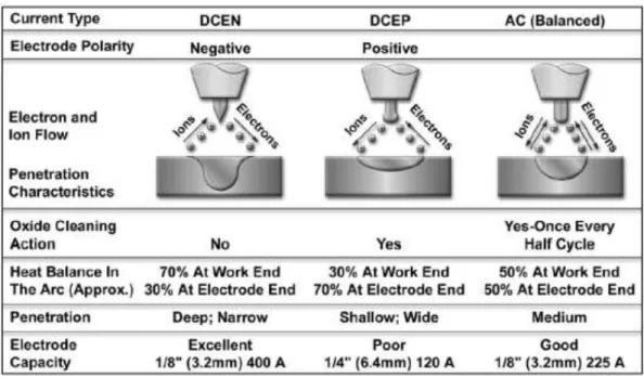
The process can be used with: direct current electrode negative (straight polarity); direct current electrode positive (reverse polarity); and alternating current. Each current type has its applications, advantages and disadvantages. The penetration pattern as well as the weld bead configuration are directly correlated with current type selection [12,13]. The characteristics of each configuration are presented and summarized in Table 2.1.
Direct Current Electrode Negative (Straight Polarity)
Direct Current Electrode Negative (DCEN) is the most common polarity used in GTAW to weld, practically, all metals, except aluminium and magnesium. In DCEN polarity, the torch is connected to the negative terminal of the power source, being the workpiece connected to the positive terminal. Thus, when the arc is established the electrons flow from the electrode to the workpiece. Since in a direct current (DC) the welding arc concentrates approximately 70% of the heat, a great amount of heat is distributed into the workpiece, leading to a deep penetration of the weld beads [12].
Direct Current Electrode Positive (Reverse Polarity)
consquence, the workpiece has less heat resulting in a shallow penetration of the weld bead. This mode is mainly used to weld aluminium and magnesium alloys because it provides a cleaning action of the base material breaking and removing surface oxides [12,13].
Alternating Current
In order to obtain the advantages of both DCEN and DCEP, namely: good cleaning action and good penetration, alternating current is used. In this case, the terms of positive and negative applied to the electrode and workpiece are not considered since the current/polarity is always alternating, the flow direction, operating in cycles. During a complete cycle there is one half cycle when the electrode is positive and another in which it is negative, as the workpiece has opposite signal of the electrode [12,13].
Table 2.1- Characteristics of current types for Gas Tungsten Arc Welding.
Pulsed Mode
The welding speed also modifies the weld bead shape. For the same current intensity and voltage, increasing the welding speed results in a decrease of the heat input, hence producing a small weld bead.
The heat input (H) is a measure of the energy transferred from the arc to the workpiece per unit length of a weld. It is an important parameters because, like preheat and interpass temperature, it influences the cooling rate, which may affect the mechanical properties and metallurgical structure of the weld and the Heated Affected Zone (HAZ). Heat input is typically calculated as the ratio of the power to welding speed velocity of the heat source as follows:
(2.1) Where,
The heat transfer efficiency , can be determine experimentally by calorimetry or taken from available data which in the case of TIG is of 0.7 %.
TIG welding allows a precise control of heat input and heat addiction providing superior qualities welds, with low distortion and free of spatter. Although heat input is small when compared with other arc welding processes, it presents an heat input about ten times higher than laser welding, causing extended heat affected zone (HAZ) in the welded sample [3,12].
2.3.2
- Laser Welding
Laser beam radiation is a coherent and monochromatic beam of electromagnetic radiation produced by stimulated emission. In fact, LASER is an acronym for Light Amplification by Stimulated Emission of Radiation.
melting of the work piece, providing the joint upon cooling. The effectiveness of the beam coupling depends on the wavelength of the beam radiation and the optical properties of the material, including the surface conditions. There are two fundamental modes of laser welding depending on the power density, focal joint position and the beam mode, represented in Figure 2.13: (a) "keyhole" or penetration welding and (b) conduction welding [1,6]. Both modes can occur simultaneously in a joint.
Figure 2.13- Laser welding modes: a) "keyhole" and b) Conduction [14].
In a "keyhole" laser welding mode, high power density is used for material joining, leading to the formation of a cylindrical cavity of metallic vapour throughout the material thickness. The cavity is sealed up by the molten walls as the process progresses. The weld is characterized by a parallel sided fusion zone and a narrow width. Conduction laser welding is obtained for low power density, where most of the beam energy is lost by reflection. The energy absorbed by the material is below a threshold value, sufficient to melt the material but not enough to vaporize it, leading to heat conduction into adjacent regions. Conduction mode is characterized by a wide and low penetrated molten pool, similar to TIG welding. [3,6,14]. Recently [15] found that this mode has advantages over keyhole since the thermal gradient is not so steeper, which can be useful in difficult to weld materials and in dissimilar joints.
2.4
- NiTi Similar Joints
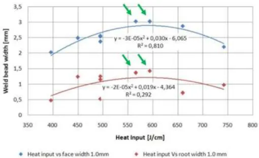
Most of reported studies dealing with welding and joining of SMAs concern laser welding, since arc welding processes commonly produce welds with extended HAZ, not desirable in most cases. Limited information can be found regarding welding SMA using arc welding techniques. Ikai [16] successfully performed microweldeds on NiTi thin wire (outer diameter of 0.75 mm) and sheet (0.2 mm thickness) using TIG welding, but significant degradation of weld mechanical properties was observed.
the face and in the root that is with low aspect ratios typical of a conduction weld. These are marked in figure 2.14 with an arrow.
Figure 2.14 - Relation between heat input and the weld bead face and root width. Adapted from [1].
2.5
- Applications
Shape Memory Alloys characteristics and functionalities present a vast interest for a wide range of industries. Since their discovery a large number of patents have been issued for every conceivable application using SMA. However, only few applications have had commercial success. The lack of knowledge and technology available to overcome technical difficulties associated to SMAs were the main reason [1,8,17].
2.5.1
- Aerospace Applications
Aerospace industry is known for demanding state of the art materials and technologies. Smart materials lead to new design concepts, allowing fully integrated and distributed actuation by means of simple mechanisms that do not add weight. SMA technology is implemented in the aerospace industry, with great success, and has been used for areas such as: fixed-wing aircraft, rotorcraft and spacecraft. Despite previous achievements the work in all these areas is still progressing [1,8].
Fixed-Wing Aircraft Applications
There have been a number of other efforts to integrate SMA elements into aerostructures.
Engine noise levels during takeoff and landing have become more highly regulated worldwide. To reduce this noise, some designers are installing chevrons onto engines to mix the flow of exhaust gases and reduce engine noise. Research is being performed into methods by which SMA beam components can be embedded inside chevrons (Figure 2.15). The SMA beams bend the chevrons into the flow during low-altitude flight or low speed flight, thereby increasing mixing and reducing noise. During high-altitude and high speed flight, these SMA beam components will cool into martensite, thereby straightening the chevrons and increasing engine performance [8].
Figure 2.15 - Variable geometry chevron [8].
Rotorcraft
The role of SMAs in rotorcraft applications has been focused on the main rotor. The research is based on actuating SMA blades. These SMA blades, when actuated, could twist and facilitate the formation of different blade configurations and thereby optimize performance of such aircraft in both the hover and forward flight regimes.
SMAs are ideally suited for such applications because of their high actuation energy density and forces required in the small available volume within a rotor blade [8].
Spacecraft Applications
SMAs have been used in space applications to address problems related to actuation and
release in zero atmosphere environmentas well as vibration damping during spacecraft launch.
One such application that uses SMAs is for the low-shock release mechanism in satellites.
Some space missions experienced failure due to shock caused by the pyrotechnic release mechanisms, in some cases, causing the mission to be aborted. The slow actuation due to gradual heating in SMAs makes them suitable for low shock release mechanisms in space
applications, in this case the SME isused [8].
SMAs are also used in actuation of various components such as solar panels. The
Lightweight Flexible Solar Array (LFSA) used thinSMA strips as hinges, which deploy the folded
solar panels upon heating in approximately 30 seconds [8]. The concept design is shown in
Figure 2.16.
Figure 2.16 - SMA hinges. Folded and deployed configuration [8].
stiffness from the initial elastic region to that in the transformation region makes it an effective tool to isolate vibrations [8].
2.5.2
- Medical Applications
NiTi alloys properties such as SME and SE characteristics combined with biocompatibility make them an attractive material medical applications. The combination of these properties has lead to the development of various applications, from stents to orthodontic wires, as well as devices for minimal invasive surgery [8].
Orthodontic Applications
The properties of SMAs have been successfully implemented in a variety of dental applications. Since the 1970's NiTi orthodontic archwires have been used for being more effective than other alternative materials (Figure 2.17 - a)). Combining NiTi with other materials allows obtaining selective components that are able to control the force applied on each teeth, resulting in a more effective solution. Another dental application for SMAs involves the use of NiTi drills used in root canal surgery, which involves careful drilling within the tooth (Figure 2.17 - b) ). The Nitinol drills can bend to rather large angles, which induce large strains, yet still withstand the high cyclic rotations [1,8].
Figure 2.17 - Orthodontic applications of NiTi SMA: a) NiTi braces; b) schematic of a NiTi drill used for root canal surgery [8].
CardiovascularApplications
A more common cardiovascular application is the “self-expanding” NiTi stent. Like other conventional stents, this device is used to support the inner circumference of tubular passages in the body such as blood vessels. Traditionally, stents are made using stainless steel, that could damage the vessel when applied. Self-expanding NiTi stents provide an attractive alternative to the traditional method. After being constrained, the NiTi stent is introduced and released in the artery. There it expands to its original larger diameter and gently pushes outward on the walls, considering that the temperature exceeds the As
temperature of the stent material. Figure 2.18 - b) shows an illustration of a NiTi stent in the constrained and deployed configuration [8].
Figure 2.18 - Cardiovascular applications: a) Simon's filter in deployed configuration; b) Self-expanding NiTi stent [8].
Surgical Instrument Applications
2.5.3
- Transportation Applications
Shape memory alloys have been used in automobiles for applications ranging from impact absorption to sensing and actuation. The superelastic behaviour hysteresis provides an effective system to dissipate vibrations and impact. and has been used for impact absorption on armour vehicles in military and commercial applications. The SME has also been implemented for remote opening and closing of louvers on automobile fog light to prevent damage from the road debris. A series circuit ensures the actuation of the SMA louvers every time the fog lamps are turned on [8,17].
SMAs can also be used for sensor and actuation purposes simultaneously. An application that exploits this behaviour is the SMA spring for the continuous variable transmission in the Mercedes A class. The spring acts as a sensor that monitors the temperature and actuates a valve at a specific temperature, which changes the direction of oil flow. A similar actuation system is incorporated in the Shinkansen bullet train gearbox where the temperature in the gear box is monitored and an SMA spring actuates a valve to adjust the oil level in the gearbox. Other applications developed for trains include the thermally actuated switch for the radiator fan in diesel engines and steam traps for the steam heating system in passenger trains. Both of these applications utilize the shape memory effect [8].
2.5.4
- Other Applications
There are many other fields and applications that incorporate and take advantage of SMAs characteristics.
The possibility to use SMA in different patterns and produce complex shape changes such as rolling, spiralling, arching and folding, can open prospects for other novel design applications using SMAs [1,8].
2.6
Summary
In this chapter it was described the characteristics and the technological interest of shape memory alloys, specially NiTi. The mechanism involved in both SME and SE have been addressed. The possibility to join this material would open up new possibilities to manufacture complex components without losing either shape memory effect or superelasticity.
Two welding processes have been described: laser and TIG. Both processes have low heat inputs, limiting the material transformation in the heat affected zone, though laser welding has a higher density then TIG.
3
- EQUIPMENT DEVELOPED
This chapter describes new pieces of equipment designed and manufactured to produce the welds and the adaptations introduced in the weld source. Also, existing equipment for shape memory effect evaluation had to be adapted for this study.
3.1
- Positioning Device
To assure the plates position for welding, a special jig was designed and manufactured based on the following functional requirements:
- To allow a tight fit of the samples for butt welding;
- To assure, a good shielding gas in the face and in the root to prevent oxidation since NiTi easily oxides at temperatures above 500 °C;
- To facilitate welding fumes to escape;
- To enable process visualization.
The positioning device consisted in two distinct parts:
underneath by a stainless steel tube welded to it, so the base bead had to be elevated. Near the exit of the gas flow protection a diverter was necessary to avoid direct contact of the gas flow with the weld still molten. The base also was elevated to allow the assess of the shielding gas feeding tube.
- A chamber to contain the shielding gas, with a trapezoidal prism shape, open on the top, to allow the weld fumes to escape (Figure 3.2). This chamber was also made in stainless steel while the lateral faces were made from transparent acrylic, to enable the process visualization.
Figure 3.1- a) Top view of the base - central canal and position rulers mounted; b) perspective view of base with position rulers mounted.
Figure 3.2- Welding chamber.
3.2
- Trigger Device
Since the welding torch had to be manually activated during the entire welding process, two major problems were detected with the TIG welding machine: speed variation of the torch and variation of the distance of the tungsten electrode to the welding plate. Both problems identified were due to pressure variations done on the activation button. As a solution, a small trigger device was developed to avoid disturbance on the torch and also to assure that the process would be consistent and repeatable. The device developed consisted on an ON/OFF switch with the purpose to activate and deactivate the torch. The device was manufactured using a 3D printing machine.
Figure 3.3 - Trigger device: a) ON; b) OFF.
The technical drawings which depict of the trigger device are presented in annex B.
3.3
- Adapted Equipment
3.3.1
Moving Table
generator) making the program suitable for any computer. The program also recognized the limit sensors installed, to avoid damaging the structure while operating.
a) b)
Figure 3.4 - X-axis Table: a) over view of table; b) set up.
Figure 3.5 - Robot arm control program interface.
3.3.1.1
Testing Device For Shape Memory Effect Evaluation
The testing device (Figure 3.6) for SME evaluation was previously developed by Vieira [1] for 1 mm thick plate samples.
diameter. Machining of the existing device was performed to accomplish with these requirements and is shown in Figure 3.7.
Figure 3.6- Device used for shape memory effect testing.
4
- EXPERIMENTAL PROCEDURE
This chapter is divided in three subthemes, each one concerning:
- Materials - properties of the material used throughout the study are described, as the samples shape and dimensions.
- Welding Equipment.
4.1
- Materials
In this study NiTi was used, with a composition of 50.8 at.% Ni, to make similar NiTi/NiTi butt joints. The plates had 1.5 ± 0.1 mm thickness from Memory-Metalle GmbH Alloy S (superelastic standard alloy) had an austenitic finish temperatureof about 0 °C, flat annealed and surface oxide free. General physical and mechanical properties of the alloy are displayed in Tables 4.1 and 4.2, respectively.
Table 4.1- Physical properties of NiTi SMA [19].
Physical properties of NiTi SMA
Melting
point Density
Coefficient of thermal
expansion Thermal conductivity Specific heat Martensite Austenite Martensite Austenite
[°C] [kg/dm3] [x10-6 K-1] [W/m. K] [J/kg. dm3]
1300 6.45 6.6 11 8.6 18 322
Table 4.2- Mechanical properties of NiTi SMA [19].
Mechanical properties of NiTi SMA
Young modulus Ultimate tensile
strength Elongation Poisson
ratio Martensite Austenite Cold
worked Hot worked Cold worked Hot worked
[GPa] [MPa] [%] -
70-83 28-41 1900 895 5-10 25-50 0.33
The NiTi plates were cut into squares of 30x30 mm sample, using a precision cut-off machine ATM GmbH model Brilliant 221, equipped with a diamond wheel type B102 from the same maker. Cutting parameters were:
- Speed: 3500 rpm;
- Feed rate: 1 mm/min;
- Lubricant: multipurpose cutting fluid.
After cutting the samples were hand finished and chemically cleaned using a solution of 10% HF + 45% HNO3 + 45% H2O to remove cutting moisture contamination and surface
4.2
- Welding Equipment
A TELWIN, TECHNOLOGY TIG 182 AC/DC-HF/LIFT (Figure 4.1), was used to produce the welds. The main characteristics of the GTAW equipment are presented in Table 4.3.
Figure 4.1- TELWIN, TECHNOLOGY TIG 182 AC/DC-HF/LIFT.
Table 4.3 - TELWIN, TECHNOLOGY TIG 182 AC/DC-HF/LIFT Technical Data [20].
Code 815332 Current range 5 - 160A Max. current (40°C)(EN60974-1) 160A 20%
Current at 60% (EN60974-1) 85V Max. no load voltage 94V
Absorbed current 18 - 29 A Absorbed power 2.5 - 4.3 kW
Efficiency 75% Power factor 0.7 cosφ MMA electrode diameter 1.6 - 3.2 mm
Protection class IP23
4.3
- Experimental Approach
4.3.1
- Butt joints
Preliminary tests were made on 2.0 mm thick stainless steel plates, to determine processing parameters, including shielding gas flow rate. Commercial stainless Steel (AISI 316) was used since it is a less expensive material than NiTi and has similar thermal conductivity coefficient.
Using direct current (DC) and straight polarity and Argon (98%) as shield gas, several tests were performed to have good welds with full penetration, good surface aspect and free of oxides.
A pure tungsten non consumable electrode was used with 2 mm diameter.
Welding parameters were varied keeping the welding speed constant at 20 cm/min. The gas flow was kept at 15 l/min in the torch , which was the maximum admissible flow that did not interfere with the molten pool and the best flow rate in the root was 12 l/min with a similar objective. So the best parameters are discriminated in Table 4.4.
Table 4.4- Welding parameters chosen to weld the NiTi/NiTi butt joints specimens.
Welding Speed
Electric
Current Heat Input
Gas flow
Torch Root
[cm/min] [A] [kJ/cm] [l/min]
20 45 (DCEN) 1.512* 15 8
* According to expression (2.1)
According to Vieira [1], the best mechanical properties were attained with welds performed across the rolling direction, and so were the welds made for this study.
Samples Preparation For Testing
Figure 4.2 - Specimens extracted from welded samples.
Table 3.6 presents specimen reference and characterization tests performed.
Table 4.5 - Specimens references and tests performed.
Sample reference Specimen reference Test
#1.1
#1.1.1 8% cycling
#1.1.2 12% cycling
#1.1.3 DSC and DRX
#1.2
#1.2.1 SME
#1.2.2 12% cycling
#1.2.3 Tensile Test
#1.3
#1.3.1 6% cycling
#1.3.2 Microscope, SEM/EDS and microhardness
#1.3.3 7% cycling
#1.3.4 Tensile Test
4.3.2
- Testing Methods
- Microstructure Observations
- Differential Scanning Calorimetry - DSC
Differential Scanning Calorimetry (DSC) is a thermal analysis technique that measures the material’s heat capacity (cp) variations with temperature. A sample of known mass is
heated or cooled and the changes in its heat capacity are tracked as changes in the heat flow [21].
A DSC 204 F1 Phoenix model from Netzsch was used to perform high and low temperature structural tests and characterize the Base Material (BM), as well as, the weld and the Fusion Zone (FZ), in terms of zero-stress structural transformation temperatures. Liquid nitrogen was used on low temperature tests. Both BM and FZ specimens, were cooled down to -150 °C and heated up to 150 °C. The cooling and heating rate was 10 °Cmin-1.
- X-Ray Diffraction Analysis - XDR
XDR technique was used to analyze separately the phases presented in BM and FZ. With this test, it was supose determine the phases present in the FZ and to compare these with the ones in the BM.
XRD analysis were performed using a Rigaku DMAX IIIc, 40 kV/30mA, with conventional θ/2θ scanning at room temperature and a PANalytical's X'Pert PRO MRD with a geometry of Bragg-Brentano and a Cu K-alpha (wavelength 1.540598 Å) X-rays source.
- Microhardness Measurements
Microhardness measurements were performed along the cross-section of the welded specimen, using a Mitutoyo HM-112 microhardness tester by applying a test load of 500mN. Two Vickers microhardness profiles were made on the specimen, one near the weld root and the other near the top. The indentations done were spaced more than three diagonals from each other and from the boarders.
- Mechanical Tests
Uniaxial Tensile Testing
determine the Ultimate Tensile Strength (UTS) and elongation to fracture of the welded sample. The tests were performed at room temperature. A test previously performed on the BM was used as reference for comparison purpose. The chosen specimens are presented in Table 3.7.
Table 4.6 - Uniaxial tensile test specimens.
Specimen Reference
Gauge Length
[mm]
Base Material 16.30
#1.3.4 32.25
#1.2.3 30.00
Cycling Tests
Using the equipment previously described, cycling tests were performed on 5 different welded samples. These tests allowed the study of the weld's superelasticity behaviour and the analysis of the accumulated irrecoverable strain developed with the increase of the number of completed cycles. The welded samples were subjected to 10 sets of 60 complete cycles, in a total of 600 if the sample did not break. The chosen samples are present in Table 3.8.
Table 4.7 - Cycling test specimens
Specimen Reference
Max. Elongation Gauge Length
[%] [mm]
# 1.3.1 6 31.50
# 1.3.3 7 29.50
# 1.1.1 8 29.50
# 1.2.2 12 35.00
# 1.1.2 12 32.00
- Shape Memory Effect - SME
The fundamentals of the test lies on the pure elastic bending theory, synthesized and briefly presented in Figure 3.13 and 3.14, in which the strain varies linearly over the thickness, as presented in equation (4.1).
Figure 4.3 - Schema of pure bending [20]. Figure 4.4 - Bending section [20].
(4.1)
Where,
According to the previous equation 3.1, strain varies linearly over thickness and the highest strain occurs on the inner and outer surfaces. As stated before, the device was modified and had the capability of inducing 3 distinct levels of strain, according to the diameter selected and sample thickness. Considering 1.5 mm thick samples (y = 1.5 mm) and the diameter in the middle (ρ = 22.5 mm) the strain level induced was 6.7%.
Liquid nitrogen was used to assure that the test was conducted below the parent phase temperature and the bending was conducted using the special mechanism to bend the
5
- RESULTS AND DISCUSSION
The tests were performed to determine how the welding process would alter the properties of the welded specimen when compared to the BM. The results are presented by the following sequence:
- Preliminary observations of the weld bead;
- Structural observations of each zone of the welded samples (HAZ, FZ and BM);
- DSC analysis to determine the transformation temperature ranges;
- XRD measurements that allow structural characterization of the welded specimens;
- Microhardness measurements done on the transverse sections of the welded specimens.
- Mechanical Tests:
- Tensile tests to determine the elongation to fracture of the welded sample and the ultimate tensile strength (UTS);
- Cyclic load/unload of the welded samples and presentation of the evolution of the accumulated irrecoverable strain with the number of cycles;
5.1
- Macroscopic observations
Similar joints samples are presented in Figure 5.1, where the top and root of the bead from welded samples can be seen.
a)
b)
c)
Figure 5.1 - Aspect of similar NiTi butt weld joints: a) sample #1.1; b) sample #1.2 and c) sample #1.3.
5.2
- Micro Observations
5.2.1
Microscope Observations
Figure 5.2 depict the microstructure of a weld evidencing the epitaxial crystal growth from the base material into the weld bead. An increase in grain size in the HAZ is evident as shown in Figure 5.3, as well as details of the micro structure of the fusion zone
Figure 5.2 - Specimen microstructure visualization.
(a)
b.1) c.1)
b.2) c.2)
Figure 5.3 - Microstructure of: a) HAZ; b) Transition HAZ/FZ c) FZ.
phases as shown in Figures 5.3 b) and c). In the central area of the weld metal a fine equiaxial structure of primary NiTi interdentritic spaces are rich in Ti2Ni (Figure 5.3 c.2)),
due to the volatilization of Ni in these region. In the interface HAZ/FZ, where the cooling rate was higher than in the centre of the fusion zone, the Ni content remained the same leading to an eutectic transformation, forming NiTi +TiNi3 (Figure 5.3 b.2)).
5.2.2
Scanning Electron Microscopy - SEM/EDS
SEM observations were performed on a welded specimen to analyse the chemical composition of the FZ. Since the non consumable electrode was made of tungsten (W), SEM observations also aimed to evaluate the presence of W inclusions in the molten material. These observations were assisted by EDS and the results are depicted in Figures 5.4 and 5.5, for the base material and fusion zone respectively.
Figure 5.4 - EDS results from Base Material
Figure 5.5 - EDS results from Fusion Zone
areas. The depletion of Ni observed may be due to the volatilization of this elements under an arc welding process of high temperature. This depletion was expected, since Ni has a higher evaporation rate than Ti [23], as shown in Figure 5.6.
Table 5.1 - Atomic percentage of Ti and Ni on the base material and fusion zone.
at.%
BM FZ Variation
Ti 49.09 50.35 +1.26
Ni 50.91 49.65 -1.26
Figure 5.6 - Vapour pressure as a function of temperature for Ni and Ti (Adapted from [6]).
5.3
- Differential Scanning Calorimetry measurements - DSC
Figure 5.7 presents the DSC curves for both the base material and fusion zone and allows to identify the transformation temperatures during cooling and heating condition.
the BM and B2 structure seems to transform to B19' upon cooling and heating, that is the R-phase is not detected, giving place to a long transformation curve, as shown in Figure 5.9. One possible way to confirm the existence of R-Phase was by performing a XRD analysis with temperature variation in the range of transformation temperatures considered. The long transformation curve, upon heating and cooling, suggests that there is a gradient of transformation temperatures because of the chemical composition gradient along the FZ, due to the temperature variation, from the HAZ/FZ interface to the centre of the weld bead, created by the welding process.
Figure 5.7 - DSC measurements of the base material and molten material for determination of the transformation temperatures.
Table 5.2- Transformation temperatures for base material and molten material.
Rs Rf Ms Mf As Af
[°C] [°C] [°C]
Base Material 20 -25 -45 -100 -10 25
Fusion Zone - - 5 -80 -55 18
5.4
- Microhardness Measurements
The indentations profiles made near the top and the weld root, on the cross section of the specimen are presented in Figure 5.9.
Figure 5.8 - Vickers Microhardness profiles made on specimen #1.3.2.
Figure 5.9 - Microhardness measurements in the cross section of the sample along weld top and root.
5.5
- X-ray Diffraction Analysis
XDR analysis results from base material and fusion zone, are presented in Figures 5.10 and 5.11, respectively.
Figure 5.10 - XRD measurements of BM.
The difference in the spectrums are due to the fact that different equipments were used in this study. The only peak identified corresponds to B2 phase. So the evaluation of the presence of Ni-Ti precipitates in the FZ, regarding microscope observations, was inconclusive. The non identification of the peak may be due to the fact that their content is below the detection limit of the available equipment. Eventually, the peaks corresponding to precipitates are overlapped with back signal noise.
5.6
- Mechanical Tests
5.6.1
- Tensile Tests
Tensile testing up to rupture was performed to evaluate the mechanical properties of the welded sample. With the results, it was possible to conclude that the welding parameters chosen were acceptable and to compare with the results of the BM.
The plots of the tests are presented in Figure 5.12. The Ultimate Tensile Strength (UTS), ductility parameters and superelastic plateau are presented in Table 5.3, for comparison.
![Figure 2.1 - σ-ε diagram. (0 - 5) martensitic deformation, heat recovery until austenitic domain (SME); (5 – 10) superelastic deformation of austenite [5]](https://thumb-eu.123doks.com/thumbv2/123dok_br/16554290.737287/26.892.309.613.571.876/figure-martensitic-deformation-recovery-austenitic-superelastic-deformation-austenite.webp)
![Figure 2.3 - Temperature-induced phase transformation of a SMA without mechanical loading [8]](https://thumb-eu.123doks.com/thumbv2/123dok_br/16554290.737287/28.892.278.635.105.372/figure-temperature-induced-phase-transformation-sma-mechanical-loading.webp)
![Figure 2.5 - Schema of the Shape Memory Effect for a Shape Memory Alloy [8].](https://thumb-eu.123doks.com/thumbv2/123dok_br/16554290.737287/29.892.269.647.543.822/figure-schema-shape-memory-effect-shape-memory-alloy.webp)
![Figure 2.6 - Temperature-induced phase transformation in the presence of applied load [8]](https://thumb-eu.123doks.com/thumbv2/123dok_br/16554290.737287/30.892.272.646.108.382/figure-temperature-induced-phase-transformation-presence-applied-load.webp)
![Figure 2.9- Representation of lattice changes in stainless steel and in a superalloy [4]](https://thumb-eu.123doks.com/thumbv2/123dok_br/16554290.737287/31.892.310.612.671.947/figure-representation-lattice-changes-stainless-steel-superalloy.webp)
![Figure 2.10- Ni-Ti phase diagram [10].](https://thumb-eu.123doks.com/thumbv2/123dok_br/16554290.737287/32.892.187.749.247.677/figure-ni-ti-phase-diagram.webp)
![Figure 2.11- Variation of transformation temperature with Ni content for binary Ni-Ti alloys [7]](https://thumb-eu.123doks.com/thumbv2/123dok_br/16554290.737287/33.892.311.614.108.400/figure-variation-transformation-temperature-ni-content-binary-alloys.webp)