Beatriz Prego Lopes Crispim
Licenciada em Ciências de Engenharia Mecânica
Gas Tungsten Arc Welding of
Cu-Al-Mn Shape Memory Alloys
Dissertação para obtenção do Grau de Mestre em Engenharia Mecânica
Orientador: Professor Doutor João Pedro de Sousa
Oliveira, Professor Auxiliar, Faculdade de Ciências e
Tecnologia da Universidade Nova de Lisboa
Co-orientador: Professora Doutora Rosa Maria Mendes
Miranda, Professora Associada com Agregação,
Faculdade de Ciências e Tecnologia da Universidade
Nova de Lisboa
Júri:
Presidente: Prof. Doutor Telmo Jorge Gomes dos Santos Arguente: Prof. Doutor Francisco Manuel Braz Fernandes
Gas Tungsten Arc Welding of Cu-Al-Mn Shape Memory Alloys
Copyright © 2018 Beatriz Prego Lopes Crispim
Faculdade de Ciências e Tecnologia e Universidade Nova de Lisboa
i
Acknowledgments
This work would not have been possible without the help and collaboration of my supervisor Professor João Oliveira. I would like to express my sincere gratitude for this opportunity, for his total availability, dedication and support during this study.
To my assistant advisor, Professor Rosa Miranda, for the knowledge shared and interest in helping and advising.
Thank you to Professor Braz Fernandes for the XDR analysis and to Doctor Daniela Gomes for the SEM/EDS analysis, performed in the CENIMAT facilities.
To Mr. António Campos and Mr. Paulo Magalhães, for all the fundamental help and support during the experimental phase of this work.
A sincere thank you to my colleagues, in particular to Tiago Gonçalves, Ana Sousa and Gonçalo Serrano, who accompanied me during these past 5 years, for their companionship, support and optimism even in difficult times. A special thanks to my colleagues David Negrão, Tiago Rodrigues and Valdemar Duarte for the essential help.
To my friends, specially to João and Mariana, for their friendship, encouragement, and for all the laughs and unforgettable times.
iii
Resumo
Recentemente, aplicações onde se utilizam ligas com memória de forma têm atraído interesse, devido às propriedades únicas desta classe de materiais. A sua aplicação estende-se a uma ampla variedade de sectores, tal como a indústria automóvel, aerospacial, biomédica e de construção civil.
Entre as classes existentes de materiais com memória de forma, o NiTi é o mais estudado. No entanto, as ligas à base de cobre estão a emergir como potenciais substitutos para o NiTi, devido aos seus custos mais baixos e potencial para aplicação em dispositivos de amortecimento.
A necessidade de desenvolver técnicas avançadas de união de materiais é de grande interesse, uma vez que irá permitir o aumento de potenciais aplicações de qualquer liga de engenharia. Assim, existe a necessidade de promover a união de ligas com memória de forma sem comprometer as suas propriedades.
O presente estudo, incide sobre a produção de juntas similares de uma liga com memória de forma
de Cu-Al-Mn através de soldadura TIG (Tungsten Inert Gas).
As juntas foram avaliadas, de forma a compreender o impacto da soldadura nas propriedades microestruturais e mecânicas das mesmas.
Verificou-se que a liga superelástica de Cu-Al-Mn apresenta boa soldabilidade e não foram detectadas alterações significativas nas propriedades das juntas em comparação com o material base. Este é o primeiro estudo reportado na literatura, que estuda o efeito de um processo de soldadura baseado no arco elétrico para a ligação destes materiais.
v
Abstract
Recently, applications using shape memory alloys (SMAs) have been attracting interest, due to their unique properties. Their application extends to a wide variety of fields, such as automotive, aerospace, biomedical and civil engineering industries.
Among the existing classes of shape memory alloys, NiTi is the most studied one. However, Cu-based SMAs are emerging as potential substitutes of NiTi, due to their lower cost and potential for application in damping devices.
The development of joining technologies is of major interest, because it allows the growth of potential applications of any engineering alloy. Thus, the necessity of studying the joining of SMAs without compromising their properties.
This study focused on the production of similar Cu-Al-Mn joints by gas tungsten arc welding. The microstructure and tensile properties were evaluated to understand the effects of welding on the microstructural and mechanical properties of the welded joints.
The superelastic Cu-Al-Mn presented good weldability and no significant changes of the overall tensile properties of the welded specimens were observed, when compared to the base material. This is the first reported study regarding the effects of welding on Cu-based shape memory alloys, using an arc-based source.
Keyworks: Shape memory alloys, Cu-Al-Mn shape memory alloys, gas tungsten arc welding,
vii
Contents
1Introduction ... 1
1.1 Motivation ... 1
1.2 Objectives ... 1
1.3 Document structure ... 1
2Literature Review ... 3
2.1 Shape Memory Alloys ... 3
2.1.1 Phase Transformation in Shape Memory Alloys... 4
2.1.2 Shape Memory Effect ... 5
2.1.3 Superelasticy ... 5
2.1.4 Cu-based Shape Memory Alloys ... 7
2.1.5 Applications ... 8
2.2 Joining of Shape Memory Alloys ... 10
2.2.1 Gas Tungsten Arc Welding ... 10
2.2.2 Gas Tungsten Arc Welding of Shape Memory Alloys ... 13
2.2.3 Welding of Cu-based Shape Memory Alloys ... 14
2.3 Conclusions ... 15
3Experimental Procedure ... 17
3.1 Material Characterization ... 17
3.2 Equipment ... 18
3.2.1 Welding Equipment ... 18
3.2.2 Trigger System ... 18
3.2.3 Motion System ... 19
3.3 Experimental Approach... 20
3.4 Characterization Techniques ... 21
3.4.1 Differential Scanning Calorimetry ... 21
3.4.2 Optical Microscopy ... 21
3.4.3 Scanning Electron Microscopy coupled with Energy Dispersive Spectroscopy ... 22
viii
3.4.5 X-Ray Diffraction ... 22
3.4.6 Hardness Tests... 22
3.4.7 Mechanical Tests ... 22
4Results and Discussion ... 25
4.1 Microstructural Characterization by Differential Scanning Calorimetry ... 25
4.2 Microstructural Characterization by Optical Microscopy and Electron Backscatter Diffraction ... 26
4.3 Microstructural Characterization by Scanning Electron Microscopy/Energy Dispersive Spectroscopy ... 32
4.4 Microstructural Characterization by X-Ray Diffraction ... 34
4.5 Microstructural Characterization using micro-Hardness Measurements ... 35
4.6 Characterization of the Mechanical Properties ... 37
4.6.1 Tensile Tests ... 37
4.6.2 Cycling Tests ... 41
5Conclusions and Future work ... 45
References ... 47
ix
List of Figures
Figure 1 - Temperature-induced phase transformation of an SMA without mechanical loading [1].
... 4
Figure 2 - Stress-strain-temperature plot exhibiting superelasticity and shape memory effect [9]. ... 5
Figure 3 - Typical superelastic behaviour of a shape memory alloy [1]. ... 6
Figure 4 – Cu-Al-Mn phase diagram. Vertical section of the Cu-Al-10at.%Mn system including martensitic transformation starting temperature [20]. ... 8
Figure 5 – (a) Schematic view of the steel frame specimen. (b) Detail of the top pin joints in the tension braces [12] ... 9
Figure 6 - Gas tungsten arc welding: (a) overall process; (b) welding area. Adapted from [34].. ... 11
Figure 7 - Characteristics of the three different polarities in GTAW [30]. ... 12
Figure 8 - Trigger system. Relay and ON/OFF switch circuit schematics. ... 19
Figure 9 - Motion system. Stepper motor circuit schematics. ... 19
Figure 10 - Welding equipment. Welding machine and trigger system (a), (c); motion system and welding torch (b); trigger and motion system (d)... 20
Figure 11 - Differential scanning calorimetry of the base material... 25
Figure 12 - Welded rod. ... 26
Figure 13 - Optical micrographs of the fusion zone of the welded Cu-Al-Mn alloy. (a) Sample #6; (b) Sample #7. ... 26
Figure 14 - Longitudinal section of the welded specimen. ... 27
Figure 15 - (a) Macrograph of the welded Cu-Al-Mn similar joint. (b) Detailed macrograph of the fusion zone, with letters from “a” to “e” identifying a specific region. ... 28
Figure 16 - (a) Unit stereographic triangle [18]. (b) EBSD Inverse Pole Figure orientation map. (c) Region “a” in detail... 29
Figure 17 - Optical micrographs of the fusion zone in seven distinct regions, identified in Figure 15 (b). The letters from A to D inside de images, identify the SEM/EDS regions analysed within the FZ. ... 30
Figure 18 - a) EBSD Phase ID. b) Region “a” in detail. ... 31
Figure 19 – SEM/EDS analysis of (A), (B), (C) and (D) regions. ... 32
Figure 20 - Compositional profile across the fusion zone in the α and β-phase regions. ... 33
Figure 21 - X-ray diffraction pattern of the weld metal from the Cu-Al-Mn joint. ... 34
Figure 22 – (a) Optical macrograph of the welded specimen schematically showing the hardness measurements. (b) Corresponding average hardness values for the region analysed. ... 35
x
xi
List of Tables
Table 1 - Mechanical properties of superelastic Cu-17Al-11Mn. ... 17
Table 2 - Shielding gas composition. ... 17
Table 3 - TELWIN Technology TIG 182 AC/DC-HF/LIFT Technical data [41]. ... 18
Table 4 - Welding parameters. ... 21
Table 5 - Average EDS measurements in the fusion zone. ... 33
xiii
Abbreviations and symbols
A Austenite
Af Austenite transformation finishing temperature
A𝑠 Austenite transformation starting temperature
AC Alternating Current
BM Base Material
d Grain size
D Wire diameter
DC Direct Current
DCEN Direct Current Electrode Negative
DCEP Direct Current Electrode Positive
DSC Differential Scanning Calorimetry
EBSD Electron Backscatter Diffraction
EDS Energy Dispersive Spectroscopy
FZ Fusion Zone
GTAW Gas Tungsten Arc Welding
HAZ Heat Affected Zone
HI Heat Input
I Welding current
M Martensite
Mf Martensite transformation finishing temperature
Ms Martensite transformation starting temperature
s Welding speed
SE Superelasticity
SEM Scanning Electron Microscopy
SMA Shape Memory Alloy
SME Shape Memory Effect
SMM Shape Memory Material
t Sheet thickness
TIG Tungsten Inert Gas
U Arc Voltage
UTS Ultimate Tensile Strength
xiv
σAf
Stress level at which the stress induced transformation from austenite to martensite finishes
σAs
Minimum stress level to start inducing the transformation from martensite to austenite
σMf
Stress level at which the reverse stress induced transformation from martensite to austenite finishes
σMs
1
1
Introduction
1.1 Motivation
Over the past decades, applications using shape memory alloys (SMAs) have been attracting interest, due to the unique characteristics of this class of materials. Their application extends to a wide variety of fields, such as automotive, aerospace, naval and biomedical sectors.
The assessment of the weldability of SMAs is of major interest, because it allows the possibility of obtaining complex structures or the combination of these materials to other engineering ones. Among the existing classes of shape memory alloys, NiTi is the most studied one. However, Cu-based SMAs have been emerging as candidates to replace NiTi, owing to their lower production costs and high damping capacity.
Previous works revealed that laser welding of a Cu-Al-Mn shape memory alloy did not result in any significant deterioration of the overall tensile properties of the welded specimens, with the Cu-based SMA presenting excellent weldability. Furthermore, other studies have also reported that gas tungsten arc welding (GTAW) has the potential to promote joining of this class of alloys and can be employed specially in applications where larger thicknesses are required, since it can generate deeper welds. Additionally, GTAW is significantly less expensive than laser welding. Thus, this study concerns gas tungsten arc welding of a Cu-Al-Mn shape memory alloy, since no previous attempts of using arc-based sources to weld any Cu-based SMAs have been reported.
1.2 Objectives
The present study aims to investigate the feasibility of producing similar Cu-Al-Mn joints using gas tungsten arc welding process. For this, a dedicated welding equipment was designed, namely an orbital welding prototype.
The main scope of this study comprised the production of full penetrating, defect-free welds in Cu-Al-Mn rods, for which different process parameters were tested. Also, structural and mechanical characterization techniques were used to evaluate the welded specimens.
1.3 Document structure
2
- Chapter 1: details the motivation and objectives for this study.
- Chapter 2: contextualizes the study, by presenting the literature review of the existing knowledge regarding Cu-based SMAs.
- Chapter 3: describes the materials, equipment and characterization techniques used throughout this work, along with the experimental procedure adopted. The welding equipment characteristics are included.
- Chapter 4: presents and discusses the results of this study, organized according to the
characterization techniques performed.
3
2
Literature Review
2.1 Shape Memory Alloys
Shape memory alloys (SMAs) are a unique class of shape memory materials (SMMs), that present two peculiar and attractive properties: shape memory effect (SME) and superelasticity (SE). The shape memory effect is a distinct property of certain alloys that exhibit a reversible martensitic transformation, detailed later in this chapter, which was possibly the most studied metallurgical phenomenon during the early 1900s, and first established as an irreversible process. The concept of reversible transformation of martensite was presented in 1949 by Kurdjumov and Khandros, and was based on experimental observations of the thermally reversible martensitic structure in Cu-Zn and Cu-Al alloys, being later demonstrated in other alloys [1,2]
The finding of the SME can be traced back to 1932, being first discovered in an Au-47.5Cd (at.%) alloy by Chang and Read [3]. However, the breakthrough for engineering applications was only triggered in 1963, when significant recoverable strain was observed in NiTi alloys, by Buehler et al. [4].
During the 1970s, several biomedical applications using NiTi emerged, but it was not until the 1990s that relevant NiTi applications had commercial impact.
Nowadays, the demand for shape memory alloys has increased and they can be found in a wide variety of industrial fields, and are commercially desired specially for sensing and actuation applications, and as energy absorbing and damping materials [1,5].
4
2.1.1 Phase Transformation in Shape Memory Alloys
As previously mentioned, both the shape memory effect and superelasticity presented by these alloys, are due to a reversible martensitic transformation.
SMAs have typically two phases, each with a different crystal structure and consequently different properties: a low temperature one, known as martensite (M), and a high temperature one, known as austenite (A) [8]. In these alloys, each martensitic crystal has a given different orientation, called variant. The assembly of martensitic variants can exist in two forms: twinned martensite, which is formed by a combination of self-accommodated martensitic variants to keep the overall shape when martensite is thermally induced, and detwinned martensite in which a specific variant is dominant in the system, usually as a result of an applied external load [1,8]. The schematic of the crystal structure of twinned martensite and austenite for a shape memory alloy and the transformation between them is represented in Figure 1.
Figure 1 - Temperature-induced phase transformation of an SMA without mechanical loading [1].
Thermo-responsive shape memory alloys present four characteristic temperatures associated with the phase transformation, namely austenite start temperature (As), austenite finish temperature
(Af), martensite start temperature (Ms) and martensite finish temperature (Mf).
5 such transformations occur only by effect of temperature, the macroscopic shape change is negligible [8].
2.1.2 Shape Memory Effect
If a deformation is imposed to the material in the martensitic phase, it is possible to detwin the martensite by reorienting a certain number of variants. The detwinning process results in a macroscopic shape change, where the deformed configuration will be retained by the material, even after the load is released, provided that it remains in the temperature range where martensite is the stable phase. It is possible to recover the original shape when the material is heated above the Af temperature. When the As temperature is surpassed, the shape memory effect starts to
occur. In other words, the material starts to recover the previously imposed deformation, leading to the complete recovery of its original shape when the Af temperature is reached. Further cooling back to the martensite domain, will occur with no significant macroscopic shape change of the material [1,8]. Figure 2 schematically represents both superelasticity and shape memory effect in a stress-strain-temperature diagram.
Figure 2 - Stress-strain-temperature plot exhibiting superelasticity and shape memory effect [9].
2.1.3 Superelasticy
6
The superelastic behaviour of SMAs is associated with a stress-induced transformation. Superelasticity occurs by the application of stress when the material is in the temperature range of thermally stable austenite, and then progresses under an applied load to a state at which detwinned martensite is stable, finally returning to the austenitic phase when returned to zero stress state, provided that the imposed deformation does not exceed the stress to induce slip. To better illustrate this behaviour, the path depicted in Figure 3 is taken into consideration (A → B → C → D → E → F → A).
Figure 3 - Typical superelastic behaviour of a shape memory alloy [1].
Firstly, when a mechanical load is applied there is elastic deformation of austenite (A→ B). At B, for a given stress, σMs, the martensitic transformation starts to occur. The transformation
continues (B → C), to the stress level (σMf) where the loading path intersects the Mf
transformation surface. When σMf stress is reached, the material is fully martensitic. From C to
D there is the elastic loading of detwinned martensite. From D to E the martensite elastically unloads. At point E, for a σAs stress level the martensite to austenite transformation starts to occur
and proceeds until it is finished (at point F). Complete removal of the imposed stress allows for the elastic unloading of austenite (along the path F→A) [1,10].
7
2.1.4 Cu-based Shape Memory Alloys
Among the different available Cu-based shape memory alloys, a Cu-Al-Mn alloy is going to be studied in the present work. Hence the fact that this section is focused on this particular class of alloys.
Although a large number of shape memory alloys has been discovered, most are Cu-based. In particular, the Cu-17Al-11.4Mn (at.%) alloy exhibits the highest performing superelastic properties among Cu-based SMAs and has mechanical properties that are similar to those of NiTi, but has better thermal and electrical properties, and can exceed the recoverable strain achieved by NiTi [11,12]. These advantages have recently motivated numerous investigations into these alloys. The Cu–Al binary system is the most important of the Cu-based SMAs because of its superior properties, namely excellent ductility [13,14].
The metastable β-phase orders during cooling, and for a certain range of compositions ((Cu0.75Al0.25)1−xMnx, being 0 ≤ x ≤ 0.09 and Cu3Al1−xMn2x, with 0≤ x ≤ 0.22), at lower
temperatures experiences a first-order, diffusionless, structural transition into a closer packed phase [10,15]. This is the basis of the martensitic transformation in Cu-based alloys.
However, problems may emerge for Cu-based alloys with high Al content with the β2or the β1
ordered structure. Cu-based SMAs such as Cu–Al–Ni and Cu–Zn–Al with a polycrystalline structure are too brittle to be sufficiently cold worked and have very low fatigue strength. Furthermore, the low ductility of Cu-based shape memory alloys, is usually attributed to large grain size, high degree of elastic anisotropy and grain boundary segregation of impurities. This can be considered a setback in terms of practical applications, although several attempts to improve the ductility of these alloys by grain refining have been made [10,16].
The effect of the Al content on the shape memory effect and superelastic properties was studied by Kainuma et al. [17] in 1995. The authors first reported, that Cu–Al–Mn alloys with low Al composition (<17 at. %), demonstrated an exceptional ductility, as well as stable superelastic properties and excellent cold-workability. From that point onwards, special attention was dedicated to these materials.
8
of the superelastic plateau thus, the ability to recover imposed deformation by superelasticity decreases [18–20].
The phase diagram for a Cu-Al-Mn alloy is represented in Figure 4. It can be observed that the transition temperatures of order-disorder transitions β (A2) → β2(B2) and β2 (B2) → β1(L21) severely decrease with the Al content. Increasing either the Mn or the Al content of the alloy decreases the transformation temperatures, with a greater sensitivity to modifications in the Mn content. The α-phase, which can also appear in these shape memory alloys, has a face centered cubic structure. In these complex Cu–Al–Mn systems, three different low phase temperature (martensite) structures can occur, depending on the composition of the Cu-Al-Mn alloy:
α′
1(3R structure) forms with low Al content, β′1(18R structure) forms in an intermediate
range and the γ′
1(2H structure) phase is predominant in higher Al content ranges [10,16].
Figure 4 – Cu-Al-Mn phase diagram. Vertical section of the Cu-Al-10at.%Mn system including martensitic transformation starting temperature [20].
2.1.5 Applications
9 applications in multiple fields, for instance in the biomedical, aerospace and automotive industries, and especially in civil engineering in structural vibration control applications [1,11,12,16,21–25]. Although NiTi is currently the most used SMA, Cu-based shape memory alloys are arising as potential alternatives, and they are being considered as a replacement of NiTi in vibrational and damping applications, like seismic devices [12,23,24].
Since conventional steel tension braces often present degraded stiffness and strength under cycling loading, Araki et al. [12] studied the possibility of using Cu-Al-Mn superelastic alloys as energy dissipating and recentering elements, in tension braces in steel frame structures as partial replacement of steel bars, depicted in Figure 5. Both static and dynamic tests showed the effectiveness of the Cu–Al–Mn superelastic alloys brace system in controlling the behaviour of the steel frame, presenting a more stable response under cyclic loading when compared to steel. The results also showed their negligible rate dependency to high-frequency excitations, demonstrating that the use of Cu–Al–Mn alloys in seismic applications has great potential [14,23].
In the medical field, the application of Cu-Al-Mn based SMAs as guidewires was introduced, making them unique guidewires, because of their functionally graded properties. These graded properties attained by microstructural control cannot be achieved in guidewires made of NiTi and stainless steels. Cu–Al–Mn-based SMAs can be produced not just as sheets and wires, but also as tubes and thin foils, making their application less limited [16]. Also in the field of biomedical applications, the superelastic Cu-17Al-11Mn SMA is a primary candidate and is currently used for ingrown nail correction as it does not present risks to the human health [14].
Figure 5 – (a) Schematic view of the steel frame specimen. (b) Detail of the top pin joints in the tension braces [12]
10
2.2 Joining of Shape Memory Alloys
A wider application of shape memory alloys in multiple industrial sectors is inhibited by the difficulties in their processing. SMAs have poor workability when it comes to conventional machining processes [26], and their increasing importance makes the development of suitable joining techniques in order to obtain complex shaped components crucial.
Welding of shape memory alloys presents challenges when compared to welding performed on other alloys because, opposite to most materials, SMAs properties are heavily dependent on the chemical composition, microstructure and transformation temperatures, so it must be ensured that, after joining, the superelastic and shape memory effect properties are maintained [27].
The number of studies reported in the literature, regarding welding techniques of SMAs, have shown substantial growth in the last few decades. Since this study concerns gas tungsten arc welding of a Cu-Al-Mn shape memory alloy, this chapter presents this process and studies regarding welding of Cu-based SMAs. Concerning specifically to gas tungsten arc welding, no previous attempts of welding any Cu-based shape memory alloys using this process have been reported.
2.2.1 Gas Tungsten Arc Welding
The existence of welding can be traced back to ancient times, but it was not until the 20th century, when important scientific and technological discoveries occurred, that a wide variety of welding processes commence their commercial use. Amongst these discoveries, it is the electric arc in 1801.
The possibility of using inert gases as a shielding atmosphere for the welding arc and weld pool was first investigated in the 1920s by H. M. Hobart [28] and P. K. Devers [29]. However, it was only in the beginning of World War II that there was the necessity for further developments, when better shielding was required for joining reactive metals, such as aluminum and magnesium [30].
The process was perfected by R. Meredith and patented in 1942, being originally named Heliarc
welding [31]. This led to the first commercial development of gas tungsten arc welding
equipment.
11 Gas tungsten arc welding can also be employed with or without the addition of filler metal, usually in the form of wire. Autogenous GTAW (without filler metal) is applied in thin sections with square edges, up to 2 mm, whereas for thicker sections, V and X type edge preparations and the addition of filler metal is required [33].
The GTAW process is illustrated in Figure 6 and the four basic components of all gas tungsten arc welding setups are a torch, the electrode, a welding power source and shielding gas.
Figure 6 - Gas tungsten arc welding: (a) overall process; (b) welding area. Adapted from [34].
The main parameters of this process are: the welding current, welding speed, arc length and shielding gas. Weld bead configuration, welding speed and weld quality are directly influenced by the current type. Gas tungsten arc welding can be used with direct current (DC) or alternating current (AC), being the choice largely dependent on the material to be welded. Using direct current, the tungsten electrode can be connected to either the negative or the positive terminal of the power source. Direct current electrode negative (DCEN) is the most common configuration in GTAW. With that polarity, when the arc is established, electrons flow from the electrode to the workpiece. In DCEN most heat is concentrated on the workpiece, leading to deeper weld penetration and allowing for higher welding speed [30,33]. In direct current electrode positive (DCEP), the tungsten electrode is connected to the positive terminal and the direction of electrons and positive ions flow are reversed. In this case, most of the heat is concentrated on the electrode, which produces degradation of the tip, consequently the workpiece has less heat resulting in a shallow penetration of the weld bead. DCEP may be of interest in welding aluminum alloys
(a)
12
because of the cathodic cleaning action created at the surface of the workpiece, that is, the breaking and removal of the refractory aluminum oxide layer [30,33]. However, alternating current suffers periodic reversal in polarity from electrode positive to electrode negative, allowing the combination of both the advantages of DCEN and DCEP per cycle, that is deep penetration and workpiece cleaning action. Thus, it avoids the disadvantages of both, making it more suitable to weld aluminum and magnesium alloys.
The characteristics of each configuration are presented and summarized in Figure 7.
Figure 7 - Characteristics of the three different polarities in GTAW [30].
The welding speed affects weld bead configuration, mainly the width, but also penetration of a gas tungsten arc weld. For the same current and voltage, increasing welding speed leads to a reduction of the heat input [33].
The heat input (HI) is a measure of the energy transferred from the arc to the workpiece per unit length of a weld, and is calculated as the ratio between the welding power and the welding speed, as follows:
𝐻𝐼 =𝑈. 𝐼𝑠 × 𝜂 [𝐽/𝑚𝑚]
Where, U is the arc voltage [V], I is the welding current [A] and s is the welding speed [mm/s]. The efficiency in the GTAW process is approximately 0.75.
13 beads of superior quality at high speeds, with low distortion and spatter-free; it is easy to obtain a stable arc even for small current intensities; welds can be done in any position; it allows the joining of materials with a wide variety of thicknesses [8,30,33,35,36].
Although GTAW presents several benefits, the heat source is not as focused as in laser welding. Therefore, when both techniques are directly compared it is observed that in GTAW welds the heat affected zone (HAZ) and fusion zone (FZ) have a higher extension, which may lead to a loss in the shape memory and superelastic characteristics.
2.2.2 Gas Tungsten Arc Welding of Shape Memory Alloys
Despite the extensive range of welding techniques employed in shape memory alloys, laser welding is, by far, the most widely used joining process, due to its particular characteristics such as low heat input, high energy density, reduced extension of the heat affected zone and fusion zone [8].
Limited information regarding the use of arc welding techniques can be found, since arc welding processes regularly produce welds with extended heat affected zones, which are not desired in most cases.
Gas tungsten arc welding was the first welding process tested in similar NiTi joints in 1961 [4], where, although no mechanical analysis was performed, the production of defect- and porosity-free joints was accomplished. However, due to insufficient protection of the molten pool during the weld, interstitial phases were observed. In 1996, Ikai et al. [37], resumed this process and successfully welded NiTi wires with different transformation temperatures, though significant degradation of the mechanical properties of the joints was observed. More recently, Oliveira et al. [36] performed a study where the welding of 1.5 mm NiTi plates in butt joint configuration using GTAW was successfully accomplished. The transformation temperatures of the fusion zone showed a slight decrease in comparison to the base material, due to Ti oxidation. The uniaxial tensile tests results exhibited an elongation to rupture of 20% and a superelastic plateau of 30 MPa, below that of the base material. The superelastic behaviour of the welds was confirmed by cycling tests performed at 4, 8 and 12% of strain for 600 cycles. The shape-memory effect was also preserved after welding, and even after 600 cycles. This work shows that although laser welding is often stated as the most suitable process for joining NiTi, GTAW also has the capability of promoting such joining, especially for industrial applications where thicknesses above 1 mm are required.
14
shallow welds in thin walled tubes, in opposition to GTAW where the weld was performed in a single pass, resulting in a HAZ five times larger when compared to the laser one.
2.2.3 Welding of Cu-based Shape Memory Alloys
Reported studies concerning welding of shape memory alloys are mainly dedicated to NiTi, although recent research has focused on the weldability of Cu-based SMAs.
Oliveira et al. [14] presented the first study on the effects of laser welding on the mechanical properties of superelastic Cu-Al-Mn wires. No significant detrimental effect to the overall tensile properties of the welded specimens was observed when compared to the base material, with fracture always taking place far away from the welds. After mechanical cycling, the welded wire demonstrated higher irrecoverable strain compared to the base material, due to the fine-grained structure of the fusion zone, whereas the base material kept its bamboo-like microstructure. Thus, concluding that the Cu-Al-Mn alloy has excellent weldability, which may lead to an increase in its use.
Post-weld processing is often performed to improve the mechanical properties of welded joints. The effect of post-weld laser heat treatment was investigated in the improvement of the mechanical properties and damping capacity of a laser welded superelastic Cu-17Al-11.4Mn (at.%) alloy [19]. It was concluded that the tensile strength of the post-weld laser processed alloy increased almost to the double of the as-welded material and base material, while the capability to absorb energy increased up to 1.7 times.
Oliveira et al. [38] also published a work regarding another Cu-Al-based SMA. In this case, laser welding was performed on the single crystal-like Cu-11.5Al-0.5Be (wt.%) shape memory alloy. Defect-free joints were obtained, with the same crystallographic texture as the base material. Similarly, the superelastic behaviour of the welded joints was preserved, revealing the potential to employ this SMA in applications requiring high damping capacities, because of their large energy absorption capacities. There is also a study concerning the effect of laser welding on the microstructure and mechanical properties of Cu-Zn open cell foams, where the laser weldability of the open cell foams was successfully confirmed, presenting reasonable mechanical properties and crack free welded beads [39].
15 properties after welding, despite the unfavourable microstructure of the fusion zone which led to an irrecoverable strain of 2% (for a maximum applied strain of 5%).
2.3 Conclusions
Shape memory alloys are now increasingly being used in many applications because of their unique properties. Amongst these alloys, Cu-based SMAs have the broadest application prospect besides that of NiTi alloys, due to their lower production cost and by exhibiting good functional properties. These alloys are currently being studied for potential applications as damping systems in seismic devices.
Joining techniques are often required to obtain complex geometries to increase the variety of potential applications. Therefore, determining the weldability of a material will allow the production of these complex shapes.
Multiple fields would benefit from dissimilar joining of SMAs to current alloys used in those areas. Thus, preliminary studies to investigate the weldability of the Cu–based alloys in similar joints are necessary.
The main scope of this work is focused in the production and testing of Cu-Al-Mn similar joints. The mechanical properties are assessed, so that future components can be successfully designed.
17
3
Experimental Procedure
This section presents the materials and equipment used throughout this study, as well as the adjustments introduced in the weld source. The experimental approach adopted to perform similar Cu-Al-Mn joints and the characterization techniques used to assess the quality of the welds are described.
3.1 Material Characterization
The Cu-17Al-11.4Mn (at.%) alloy was prepared by induction melting under an Argon atmosphere, in order to form an ingot. To obtain the Ø6 mm rods, the ingot was hot forged and cold drawn. To attain the superelastic properties, the rods were subjected to a solution treatment at 900˚C, subsequently quenched in water, and were then aged at 200⁰C, to stabilize the martensitic transformation temperatures as described in [20].
Prior to welding, the surface oxide layer was removed with SiC paper and the rods were cleaned with ethanol, so that any impurities that could interfere with the weld would be eliminated. Table 1 summarizes the mechanical properties of the material used.
Commercial pure Argon was used as shielding gas to avoid oxidation of the material. Table 2 depicts the chemical composition of this gas.
Table 1 - Mechanical properties of superelastic Cu-17Al-11Mn.
Material
Young’s modulus [GPa]
Onset for stress induced transformation [MPa] Recovery strain [%] Work-hardening rate [GPa] Tensile elongation [%]
Cu-17Al-11Mn ≈
20
[24] ≈100 to 250 [20]
Up to 12%
[24] ≈
3.4 to 4.2 [20]
Up to 18 [24]
Table 2 - Shielding gas composition.
Alphagaz 2
Ar H2O O2 CnHm CO CO2 H2
18
3.2 Equipment
In this sub-section the description of the development of an orbital welding system that allowed the production of welds in the Ø6 mm rods is presented.
3.2.1 Welding Equipment
A welding machine from TELWIN, model Technology TIG 182 AC/DC-HF/LIFT (Figure 10),
was used. The main characteristics of the equipment are listed in Table 3.
Table 3 - TELWIN Technology TIG 182 AC/DC-HF/LIFT Technical data [41].
Single Phase Mains Voltage 230 V
Mains Frequency 50 / 60 Hz
Current Range 5 – 160 A
Max Current (at 40°C) 160 A – 20%
Max. No Load Voltage 94 V
Max Absorbed Current 29 A
Max Absorbed Power 4.3 kW
Mains Fuse 16 A
Efficiency 75 %
Power Factor (𝑐𝑜𝑠𝜑) 0.7
3.2.2 Trigger System
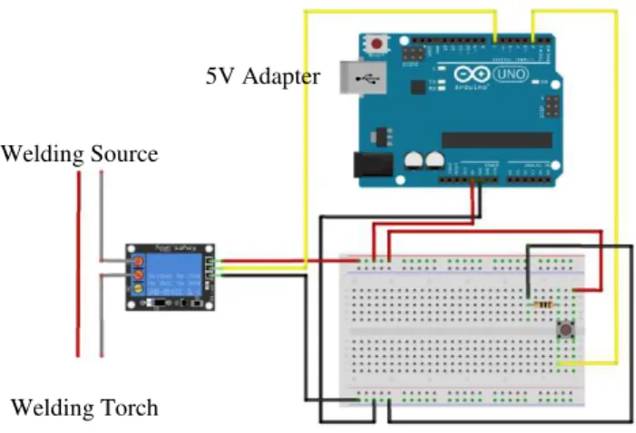
To guarantee repeatability of the conditions and parameters, such as the distance of the tungsten electrode to the welding rod, modifications were performed to allow the torch to be remotely activated, avoiding disturbances. Thus, the welding torch was fixed to a 30x30 mm Bosch
Rexroth’s profile with a 3D printed support and was triggered by adding a relay, connected to an ON/OFF switch, activated through a digital port in the Arduino, depicted in Figure 10 and
19 Figure 8 - Trigger system. Relay and ON/OFF switch circuit schematics.
3.2.3 Motion System
To guarantee rotational motion and process automation, a stepper motor was used. This type of motor is commonly employed in applications requiring precise positioning at low speeds, since they move in precise repeatable steps, allowing good control of the rotational speed. The selected model was the NEMA 17 Bipolar Motor, that has a 1.8° step angle (200 steps/revolution)
and was controlled by a DRV8880 Stepper Motor Driver Carrier. For the stepper motor to work
a power supply is also necessary, in this work, a 9V / 3A adapter was used. The motion system is depicted in Figure 10 and schematically shown in Figure 9.
Figure 9 - Motion system. Stepper motor circuit schematics.
Welding Source
Welding Torch
5V Adapter
9V/ 3mA Adapter
20
3.3 Experimental Approach
The similar Cu-Al-Mn joints were attained by varying the following welding parameters: welding speed, welding duration and welding current. Since this is the first study on arc welding of these materials, bead-on-plate welds were produced. This reduces the variability of joint-fit up, allowing the focus to be only on the welding parameters. The Argon flow rate was kept constant at 10 l/min which ensured an oxidation-free weld by visual inspection. A thoriated tungsten electrode with Ø2mm was used. Compared to pure tungsten electrodes, these possess better electron emissivity, current-carrying capacity and resistance to contamination, which results in a more stable arc [30].
Tests were performed to determine the optimum welding parameters to obtain full penetrating and defect-free welds, using direct current and straight polarity, which is the most common polarity in GTAW. In gas tungsten arc welding with DCEN, more power is located at the work end of the arc and less at the electrode tip, thus resulting in relatively narrower and deeper welds when compared with DCEP, which is normally used for welding thin sheets of strong oxide-forming materials, where deep penetration is not required [34].
(a) (b)
(c) (d)
21 Table 4 - Welding parameters.
Sample Speed [rpm]
Welding duration [s] Welding speed [mm/s] Welding current [A]
Gas flow rate [l/min]
Heat input [J/mm]
#1 15 8 9.4 35 10 31.8
#2 10 11 6.3 40 10 55.4
#3 15 9 9.4 40 10 36.9
#4 12 9 7.5 40 10 46.0
#5 10 11 6.3 40 10 55.4
#6 12 10 7.5 40 10 46.2
#7 12 11 7.5 40 10 46.2
#8 12 11 7.5 42 10 48.8
#9 12 12.5 7.5 40 10 46.2
#10 12 11.5 7.5 40 10 43.5
#11 12 12 7.5 38 10 46.2
After, the welded specimens were characterized as described in the following sub-section.
3.4 Characterization Techniques
3.4.1 Differential Scanning Calorimetry
Differential scanning calorimetry (DSC) was used to characterize the structural transformation temperatures of the Cu-Al-Mn base material. Because DSC analysis requires specimens of reduced dimensions, a precision cutting machine was used to obtain a small part of the base
material. A DSC 204 F1 Phoenix from Netzsch was used, available at the CENIMAT facilities.
The temperature range was set between -150 and + 150 ᵒC, for a heating/cooling rate of 10 K/min.
3.4.2 Optical Microscopy
Microstructural analysis was performed on the welds longitudinal section. The welded samples were cut using a precision cutting machine and mounted in epoxy resin, mechanically polished up to 2500 fine SiC paper and etched in a FeCl3 (10 g) + HCl (25 ml) + H2O (100 ml) solution.
Optical observations were then conducted at CENIMAT, using a Leica DMI5000 M optical
22
3.4.3 Scanning Electron Microscopy coupled with Energy Dispersive Spectroscopy
Scanning electron microscopy (SEM) was used for fine microstructural characterization of the fusion zone of the joints, as well as for observation of the fracture surfaces of the specimens after uniaxial tensile tests. Furthermore, energy dispersive spectroscopy (EDS) was used to assess the homogeneity of the chemical composition in both the fusion zone and heat affected zone of the
welds. These measurements were performed using a Zeiss Auriga scanning electron microscope,
available at CENIMAT, operating at an acceleration voltage of 17 kV. The samples for microstructural characterization were coated with carbon to improve conductivity.
3.4.4 Electron Backscatter Diffraction
The crystallographic orientation and phases in the fusion zone, heat affected zone and base material of the welded joints were determined by Electron Back-Scattered Diffraction (EBSD) technique. EBSD was performed using a field emission SEM at Tohoku University.
3.4.5 X-Ray Diffraction
X-ray diffraction (XRD) analysis was performed on a welded specimen to identify and characterize the phases present at room temperature. A Brucker diffractometer (rotating anode –
XM18H, Cu-Kα radiation (1.5418 Å), 30 kV/100 mA) with conventional θ/2θ scanning, available
at CENIMAT was used. The XRD technique was selected to analyse the fusion zone of the joints, since the weld thermal cycle may alter the existing phases.
3.4.6 Hardness Tests
Vickers hardness measurements were performed along the longitudinal section of the welded specimen, to access the effects of the welding process across the welded joints. A Mitutoyo
HM-112 microhardness tester was used, and a test load of 200 g was applied for 10 seconds. A total
of seventeen hardness measurement lines were performed, with indentations distancing 200 μm horizontally and 100 μm vertically, thus evaluating fusion zone, heat affected zone and base material. From these measurements a bidimensional (x, y) hardness map was constructed to evaluate the microhardness changes across the fusion zone up to the base material.
3.4.7 Mechanical Tests
The mechanical properties of the welded specimens, as well as those of the base material for reference use, were determined by uniaxial tensile tests and cycling tests. The tensile tests were
23 equipped with a load cell type SFL-50kN AG. To eliminate potential gripping problems, the
cylindrical specimens were machined, being the gauge length of the tested samples, for both base and welded material, 30 mm, as depicted in the technical drawing in Appendix A.
25
4
Results and Discussion
The experimental results of this study are presented and discussed throughout this chapter, organized by the characterization techniques used.
4.1 Microstructural Characterization by Differential Scanning
Calorimetry
The martensitic transformation starting temperature (Ms) and reverse transformation finishing
temperature (Af) of the base material were determined by differential scanning calorimetry.
Figure 11 depicts the DSC curve of the base material sample. Upon heating, only one endothermic peak is observed corresponding to the transformation of martensite into austenite. An identical behaviour is observed upon cooling. The existence of just one exothermic peak upon cooling indicates the transformation from austenite to martensite. At room temperature the base material is fully austenitic. As expected, it can also be observed that the high and low temperature peaks are symmetrical and well-defined [5,42].
26
4.2 Microstructural Characterization by Optical Microscopy and
Electron Backscatter Diffraction
The first welds produced had the purpose of evaluating process parameters, such as welding speed, welding duration and welding current, with the finality of achieving parameters that allowed the obtainment of full penetration and defect-free welds.
Microstructural observations were carried out on the welded rods (Figure 12) longitudinal section, as depicted in Figure 14.
Figure 12 - Welded rod.
Figure 13 presents micrographs of samples #6 and #7 (which welding parameters are described in section 3.3), where only partial penetration was attained, due mainly to insufficient welding duration. From these results, the effects of the welding parameters are visible, and it can be noted that
maintaining, for instance, the welding speed and current constant, varying only welding duration will lead to different weld geometries.
Welding duration and welding speed are two complementary parameters, since reduced welding speeds together with low welding time will result in welds without full penetration, since the weld will not cover the entire perimeter of the rod. Excessive welding speeds will also only result in partial penetration welds. Lower welding speeds will increase the heat input, and combined with higher welding durations can cause the material to melt completely without forming a joint, which occurred in sample #8.
Figure 13 - Optical micrographs of the fusion zone of the welded Cu-Al-Mn alloy. (a) Sample #6; (b) Sample #7. 100 mm
(a) (b)
27 For a specific set of parameters (sample #11), full penetration of the Cu-Al-Mn specimen was obtained. Figure 14 depicts the welded specimen cross-sectional view, in which the welding zones
are identified.Macrographs from the welded specimen are presented in Figure 15. Figure 15 (b)
has letters from “a” to “e” identifying a specific region, since each of these regions has a corresponding optical microscopy image, depicted in Figure 17. No welding defects such as pores or cracks were observed within the fusion zone. Microstructural analysis by optical microscopy showed the single crystal base material and revealed that the fusion zone presents a coarse grain structure, with grain size ranging from 70 μm to 1,4 mm. In the fusion zone, a columnar epitaxial grain structure is observed, which results from grain growth starting on pre-existing solid grains of the initial base material on the fusion boundary, where the thermal gradient is more severe [34] and progresses perpendicular to isothermal lines, parallel to the heat flow direction, growing towards the weld centreline where the heat flow decreases. For this specimen, the welded zone does not show symmetry. This maybe because the rods presented a slight warp from their production, which can lead to arc instability. Despite this, full penetration and defect-free joints were obtained with the optimized welding parameters.
Figure 14 - Longitudinal section of the welded specimen.
HAZ
HAZ FZ BM
BM
28
The different colours observed within the fusion zone (Figure 15 (b)) are related to differences in grain orientation [20].
Figure 16 (b) and (c) shows the inverse pole figure orientation map obtained by electron back-scattered diffraction. The colours of each grain in the mapped microstructure indicate the crystallographic orientation displayed with the same colour as those in the reference of the stereographic triangle indicated in Figure 16 (a). EBSD observations allowed the confirmation of
Figure 15 - (a) Macrograph of the welded Cu-Al-Mn similar joint. (b) Detailed macrograph of the fusion zone, with letters from “a” to “e” identifying a specific region.
Fusion Zone
a
b
c d e
Fusion boundary
1 mm
500 μm
(a)
29 the previous results (based only on colorimetric changes observed in optical microscopy). That is, the welded zone and the initial base material crystal have different grain orientations, where it can be observed that the grains present different colours and, consequently, different orientations. The columnar grains do not seem to have a preferential orientation, thus the welding process contributes to the development of near-random crystallographic texture within the fusion zone. Since the superelastic strain of single crystal SMAs strongly depends on the loading direction, texture control is important for enhancing their superelastic properties [16]. Previous studies have shown that the development of texture improves damping capacity, since textured specimens present damping properties two times higher than that of the random textured Cu-Al-Mn specimens [18].
(a)
(b)
Precipitation phenomena was observed in the fusion zone and heat affected zone (Figure 17 (b)). A large quantity of precipitates nucleated at the grain boundaries of the prior β-phase, or parent phase, showing needle shaped-like structures in the grain boundaries and within each grain (Figure 17). In some regions, this acicular morphology presents various sizes and shapes, while
Figure 16 - (a) Unit stereographic triangle [20]. (b) EBSD Inverse Pole Figure orientation map. (c) Region “a” in detail.
30
in other regions is much longer and more ordered, for example in Figure 17 (d), presenting a Widmanstätten-like structure inside the grains. Widmanstätten structures have previously been observed in Cu-based shape memory alloys [43–47]. Widmanstätten needles form in the β-phase
of metal alloys that have been cooled across the β/(α+β) phase boundary. The presence of this
transformation is based on the width of the β-phase region reducing as the temperature reaches room temperature, due to the low cooling rates induced by high arc energy processes, such as GTAW [45].
Figure 17 - Optical micrographs of the fusion zone in seven distinct regions, identified in Figure 15 (b). The letters from A to D inside de images, identify the SEM/EDS regions analysed within the FZ.
D
A
B C
(a)
(b)
(c)
(d)
31 These results were confirmed by EBSD analysis, as shown in Figure 18, where the green regions indicate the presence of α-phase and the red regions indicate the presence of β-phase showing a α (face-centered cubic, fcc) + β (body-centered cubic, bcc) two-phase microstructure.
For the Cu-Al-Mn alloy, the presence of α-phase is disadvantageous, since this phase does not only prevent martensitic transformation and shape memory effect, but also embrittles the structure [48].
(a)
Figure 18 - a) EBSD Phase ID. b) Region “a” in detail.
100 μm
a
32
Figure 19 – SEM/EDS analysis of (A), (B), (C) and (D) regions.
4.3
Microstructural
Characterization
by
Scanning
Electron
Microscopy/Energy Dispersive Spectroscopy
The compositional variation of all discernible phases after the welding process was determined by SEM-EDS analysis. A total of 18 spots within the fusion zone were analysed, as shown in Figure 19. The aim of this analysis was to determine if the formation of the α-phase was accompanied by a chemical composition change resulting from welding.
(A)
(B)
(C)
(D)
2 μm
2 μm 1 μm
1 2 6 3 4 5
2 μm 7
8 9
10 11
10 μm 10 μm
16 17
33 Although α and β-phase are close in composition, compositional changes between the two regions were clearly observed. In comparison to the base material, the remaining β matrix, has a higher Al and Mn content, due to the precipitation of the α-phase, which is richer in Cu [47]. It is possible to observe this trend along the fusion zone from the graph depicted in Figure 20. The average chemical composition results of the two phases are presented in Table 5.
Table 5 - Average EDS measurements in the fusion zone.
Region Cu [%] Al [%] Mn [%]
α-phase 71.46 ± 0.78 17.68 ± 0.75 10.86 ± 0.33
β-phase 67.87 ± 0.67 20.60 ± 0.57 11.53 ± 0.16
34
4.4 Microstructural Characterization by X-Ray Diffraction
X-ray diffraction analysis was used to determine the different phases formed in the welded specimen. The XRD pattern of the welded Cu-Al-Mn alloy is illustrated in Figure 21. By comparing results obtained with those published in the literature [42], the peaks in the patterns were identified. The main peak observed is the (200)β diffraction peak, along with less intense β- peaks and also α-phase peaks.
The X-ray diffraction results confirm the EBSD results: the weld metal exhibits a biphasic structure composed by β and α-phases.
35
4.5
Microstructural
Characterization
using
micro-Hardness
Measurements
Hardness measurements were performed on seventeen lines throughout the base material and the fusion zone as schematically represented in Figure 22 (a) (only three hardness measurement lines are represented). A representative trend of the average hardness values of the regions analysed is shown in the graph, depicted in Figure 22 (b). A large scatter of hardness values was observed where significant hardness changes were found between the FZ and the HAZ. The inability to detect hardness variations between the base material and heat affected zone may be due to the effect of annealing heat treatments performed on the base material prior to welding. Observations from previous works, regarding laser welding of Cu-Al-based alloys, have shown the same inability [14,19,38]. Solely near the fusion zone boundary, a considerable variation of values is detected. The symmetric trend of the hardness measurements both on the right and on the left of the welded zone confirms the repeatability of the results. The base material average hardness was 223.9 ± 5.9 HV, while the fusion zone was 207.1 ± 10.9 HV. These values are within the hardness
range expected for this alloy [49].
Figure 22 – (a) Optical macrograph of the welded specimen schematically showing the hardness measurements. (b) Corresponding average hardness values for the region analysed.
(a)
36
Figure 23 presents the microhardness map of the similar Cu-Al-Mn joint. A good agreement with the macrograph presented in Figure 22 (a) is evident, showing that in the fusion zone the hardness values are slightly lower than in the heat affected zone.
37
4.6 Characterization of the Mechanical Properties
4.6.1 Tensile Tests
Uniaxial tensile tests were performed on both the base material and three welded specimens, (identified as weld 1, weld 2 and weld 3) to evaluate their mechanical properties. Figure 24 depicts the stress-strain curves obtained by tensile testing at room temperature. The ultimate tensile strength and elongation to fracture results are presented in Table 6.
It can be observed that the tensile curves of the welds are identical to that of the base material, with the average stress for inducing the martensitic transformation being similar for both base material and welded specimens: approximately 250 MPa. This maybe a reflexion of the reduced welded area in comparison to the total gauge length. The ultimate tensile strength of the base material (424.3 MPa) is lower than that of the welds 1 (445 MPa) and 3 (843.6 MPa), and slightly higher than weld 2 (360.2 MPa). The most striking observation is the significantly higher tensile strength presented by weld 3 when compared to the other tested specimens, which may be due to the dependence of crystal orientations and loading direction. In fact, within the gauge length of the tensile specimens the number of grains which are strained may vary. Since these alloys have very large grain size, any minor variation of the number of available grains within the gauge length can significantly alter their mechanical properties.
38
Figure 24 - Tensile behaviour of the Cu-Al-Mn base material and welded specimens.
Table 6 - Strength and ductility parameters from tensile test results.
Sample [MPa] UTS Elongation to fracture [%]
Base Material 424,3 25,8
Weld 1 445 31,3
Weld 2 360,2 37,9
Weld 3 843,6 33,1
Typically, when welding shape memory alloys, for instance NiTi, which is the most studied SMA, a decrease of the mechanical properties is noticeable due to grain growth [51–54]. That is not the case for Cu-Al-Mn shape memory alloys that do not appear to exhibit significant changes on the overall tensile properties of the welded joints, when compared to those of the base material [14,38], this is due to high temperature heat treatments used to induce the generally large grain size in the material. Thus, the temperature reached in the heat affected zone will have an almost negligible effect on the microstructure. As a result, no significant differences in the tensile behaviour of the welded material occur.
On the base material sample, significant necking was observed in the central region of the specimen where fracture occurred, as depicted in Figure 26. Remarkably, fracture of the welded specimens during tensile testing also occurred in the base material, distant from the fusion zone
Weld 1
39 (Figure 27). This is related with the fact that the relatively finer grain microstructure in the fusion zone can delay crack propagation, with the grains that present smaller sizes accommodating the load, leading this region to become less susceptible to intergranular cracking. On the other hand, in the single crystal base material, any crack that forms will propagate without any sort of blockage, such as grain boundaries. This explains the higher deformation until fracture of the welds [14,38].
Figure 25 illustrates different stages of the uniaxial tensile tests for the weld 2 specimen, until rupture, where significant necking can be observed. The different colours within the gauge length of the specimen give an indication of the number of grains that were being stressed in the base material (4 grains).
40
After the uniaxial tensile tests, SEM analysis of the fracture surfaces of the base material and weld specimens was performed. These observations allow the understanding of the fracture morphology. Figures 26 (b) and 27 (b) show the fracture surface of the analysed samples, revealing a ductile-like fracture, as evidenced by the significant presence of dimples. No influence of the welding process was observed on the fracture surface, since fracture occurred in the non-affected base material.
Figure 26 - (a) Base material after uniaxial tensile test. (b) Fracture surface of the base material.
Figure 27 - (a) Welded specimen after uniaxial tensile test. (b) Fracture surface of the welded specimen.
10 μm
10 μm (a)
(b)
(a)
(b)
12 mm
41
4.6.2 Cycling Tests
High damping materials are attracting attention for engineering applications because of the increasing need for vibration and noise control reduction in various fields. For such applications, it is required that the selected materials are capable of absorbing substantial amounts of energy, when subjected to load variations, such as seismic devices [12,23]. Therefore, the understanding of the load/unload cycling behaviour of the welded joints and its repeatability is fundamental to evaluate the viability of their use in such applications. For shape memory alloys, energy dissipation is usually performed in the superelastic regime. Ideally, any imposed external deformation can be fully restored, upon unloading.
Due to their lower production costs when compared to NiTi alloys, Cu-based shape memory alloys are being considered as substitutes for NiTi in energy-absorption devices [12,23–25]. In the present study a welded joint and the base material, for reference, were subjected to a cycling routine to evaluate their superelastic properties, where the rod was loaded with a maximum imposed strain of 8%, then unloaded to a zero-stress condition. This procedure was repeated until 100 mechanical load/unload cycles were performed. Figure 28 (a) and (b) shows the cyclic stress-strain curves for both base material and welded specimen, respectively. The overlap of the two curves is depicted in Figure 28 (c). The start of the martensitic transformation occurs approximately at the same values of the previous tensile tests. Furthermore, the superelastic curve typical of SMAs is clear after the welding process.
42
Figure 28 - Cycling behaviour of: (a) the base material; (b) the welded specimen. (c) Overlap of base material and welded specimen cycling behaviours.
(b)
43 From the load/unload behaviour of the joints it is possible to determine the evolution of the accumulated irrecoverable strain and absorbed energy per cycle of the Cu-Al-Mn weld, as depicted in Figure 29.
There are no significant differences between the cycling behaviour of the welded and base material specimens. The irrecoverable strain after the first cycle for the base material was around 1.3%. For the welded specimens a slightly higher value for the irrecoverable strain after the first cycle was observed, around 1.5%. The presence of multiple factors can affect the superelastic response of the Cu-Al-Mn alloy. These can include grain size and grain orientation. The slightly larger irrecoverable strain in the welded specimen can be attributed to: the finer grained fusion zone, which has smaller d/D ratio than the base material, which reduces the superelastic recovery upon unloading [20]. In Cu-based shape memory alloys, the recoverable strain depends on the grain size (d) relative to the size of the specimen, for sheet thickness (t) or wire diameter (D), and increases with increasing the relative grain size, defined by the relation d/t or d/D. The superelastic strain increases with increasing d/D, owing to the fact that the free surface grain boundary area also increases, which is equal to the relaxation of the grain constraint [20]. Another reason that can justify the higher irrecoverable strain is related to the presence of α-phase which does not contribute to the superelastic behaviour and to the grain orientation in the fusion zone, which is clearly distinct from the optimized texture of the base material [38].
From Figure 29, it can also be observed that the first cycle has the higher absorbed energy, which is caused by the higher irrecoverable strain. After this, the hysteric loop which gives a measure of the absorbed energy per cycle, started to stabilize both in the base material and in the welded sample. The use of the superelastic effect in applications, typically requires that the cycling behaviour along a given load/unload path is stabilized after a given number of cycles.
44
Base material Welded specimen
Irrecoverable strain Absorbed energy
![Figure 1 - Temperature-induced phase transformation of an SMA without mechanical loading [1]](https://thumb-eu.123doks.com/thumbv2/123dok_br/16565708.737792/24.892.278.618.464.720/figure-temperature-induced-phase-transformation-sma-mechanical-loading.webp)
![Figure 2 - Stress-strain-temperature plot exhibiting superelasticity and shape memory effect [9].](https://thumb-eu.123doks.com/thumbv2/123dok_br/16565708.737792/25.892.136.766.576.868/figure-stress-strain-temperature-exhibiting-superelasticity-memory-effect.webp)
![Figure 3 - Typical superelastic behaviour of a shape memory alloy [1].](https://thumb-eu.123doks.com/thumbv2/123dok_br/16565708.737792/26.892.140.681.270.658/figure-typical-superelastic-behaviour-shape-memory-alloy.webp)
![Figure 4 – Cu-Al-Mn phase diagram. Vertical section of the Cu-Al-10at.%Mn system including martensitic transformation starting temperature [20]](https://thumb-eu.123doks.com/thumbv2/123dok_br/16565708.737792/28.892.230.717.473.928/figure-diagram-vertical-including-martensitic-transformation-starting-temperature.webp)
![Figure 6 - Gas tungsten arc welding: (a) overall process; (b) welding area. Adapted from [34]](https://thumb-eu.123doks.com/thumbv2/123dok_br/16565708.737792/31.892.239.608.313.705/figure-gas-tungsten-welding-overall-process-welding-adapted.webp)
![Figure 7 - Characteristics of the three different polarities in GTAW [30].](https://thumb-eu.123doks.com/thumbv2/123dok_br/16565708.737792/32.892.139.760.339.655/figure-characteristics-different-polarities-gtaw.webp)

![Table 3 - TELWIN Technology TIG 182 AC/DC-HF/LIFT Technical data [41].](https://thumb-eu.123doks.com/thumbv2/123dok_br/16565708.737792/38.892.192.698.397.708/table-telwin-technology-tig-ac-lift-technical-data.webp)