Henrique Junior Aiveca Sánchez
Licenciado em Ciências de Engenharia do Ambiente
Aquaponics and its potential
aquaculture wastewater treatment and
human urine treatment
Dissertação para obtenção do Grau de Mestre em Engenharia do Ambiente, perfil Engenharia Sanitária
Orientador: Prof. Doutor Pedro Manuel da Hora Santos
Coelho (Prof. Auxiliar DCEA FCT-UNL)
Júri:
Presidente: Prof. Doutora Leonora Miranda Monteiro do Amaral
Arguente: Prof. Doutor António José Guerreiro de Brito
Vogal: Prof. Doutor Pedro Manuel da Hora Santos Coelho
Aquaponics and its potential aquaculture wastewater treatment and human urine treatment Henrique Sánchez
I Aquaponics and its potential aquaculture wastewater treatment and human urine treatment
© Henrique Junior Aiveca Sánchez Faculdade de Ciências e Tecnologia
Universidade Nova de Lisboa
III Agradecimentos
À Louise Lundberg, um agradecimento pela sua paixão por novos desafios, pela ajuda incansável no planeamento e construção dos sistemas aquapónicos e pela disponibilização do espaço e dos materiais que tornaram este projecto possível.
Ao Professor Doutor Pedro Coelho, um agradecimento pela orientação da presente dissertação de Mestrado, pelo esclarecimento das dúvidas que surgiram e por todos os conhecimentos que me transmitiu ao longo do percurso académico.
Ao Rob Torcellini, Aleece Landis e à Sylvia Bernstein, um agradecimento pelos recursos fornecidos on-line, pelos exemplos inspiradores de sistemas aquapónicos que construíram e pela ajuda nalgumas questões técnicas que surgiram na construção dos sistemas aquapónicos.
A todos os meus velhos e novos amigos(as) e colegas, pelo apoio e incentivo que demonstraram, pelos conselhos e pela prontidão em ajudar quando surgiram dificuldades.
Aos meus colegas do BEST Almada por tudo o que me ensinaram, por tudo o que passámos juntos e por todas as boas memórias.
À minha irmã, tios e avós pelo encorajamento em longa-distância e o apoio incondicional que sempre manifestaram.
Aos meus pais pela ajuda incondicional, pelos conselhos que me transmitiram, pela experiência que partilharam comigo e pelas lembranças de Portugal que me foram enviando ao longo destes meses.
Por fim, à Evelina pelo carinho, paciência e confiança nos momentos bons e menos bons, pela companhia e aventuras que tivemos e pela sua ajuda a rever o meu inglês na dissertação.
V Abstract
The main objective of this thesis is to study the developing fields of aquaponics and its potential for aquaculture wastewater treatment and human urine treatment.
Aquaponics is a food production system which combines fish farming (aquaculture) with soilless crop farming (hydroponics). In this thesis the concept of aquaponics and the underlying processes are explained. Research on aquaculture wastewater and human urine wastewater is reviewed and its potential application with aquaponic systems is studied. An overview of the different types of aquaponic systems and current research on the field is also presented.
A case study was conducted in a farm in Askeröd, Sweden, which involved building two aquaponic systems (System 1 and System 2) and a human urine-based aquaponic system (System 3), with different degrees of component complexity and sizes. The design, building and monitoring of System 1, System 2 and System 3 was documented and described in detail. Four day experiments were conducted which tested the evolution in concentration of Total Ammonia
Nitrogen (NH4+/NH3), Nitrite (NO2-), Nitrate (NO3-), Phosphate (PO43-), and Dissolved Oxygen
(O2) after an initial nutrient input. The goal was to assess the concentrations of these parameters
after four days and compare them with relevant literature examples in the aquaculture industry and in source-separated urine research.
Neither of the two aquaponic systems (System 1 and System 2) displayed all of the parameter concentrations in the last day of testing below reference values found in literature. The best performing of the aquaponic systems was the more complex system (System 2) combining the hydroponic Nutrient Film Technique with a Deep Water Culture component, with a Total Ammonia Nitrogen concentration of 0,20 mg/L, a Nitrite concentration of 0,05 mg/L, a Nitrate concentration of 1,00-5,00 mg/L, a Phosphate concentration of <0,02 mg/L and a Dissolved Oxygen concentration of 8,00 mg/L. The human urine-based aquaponic system (System 3) underperformed in achieving the reference concentration values in literature for most parameters. The removal percentage between the higher recorded values after the input addition and the final day of testing was calculated for two literature examples of separated urine treatment and System 3. The system had a removal percentage of 75% for Total Ammonia Nitrogen, 98% for Nitrite, 25% for Nitrate and 50% for Phosphate. These percentages still underperformed literature examples in most of the tested parameters.
The results gathered allowed to conclude that while aquaculture wastewater treatment and human urine treatment is possible with aquaponics systems, overall these did not perform as well as some examples found in recirculating aquaculture systems and source-separated urine treatment literature. However, better measuring techniques, longer testing periods and more research is recommended in this field in order to draw an improved representative conclusion.
VII Resumo
O objectivo principal da presente dissertação é a avaliação do potencial da aquaponia no tratamento da água residual proveniente de aquacultura e no tratamento da urina humana.
A aquaponia é um sistema de produção de alimentos que combina a cultura de peixe (aquacultura) com a agricultura sem solo (hidroponia). Na presente dissertação, o conceito de aquaponia e os processos subjacentes são explicados. Uma pesquisa sobre a água residual proveniente de aquacultura e a urina humana é avaliada, sendo a sua potencial aplicação em sistemas aquapónicos estudada. Uma visão geral dos diferentes tipos de sistemas aquapónicos e a pesquisa actual neste campo é também apresentada.
Um caso específico foi realizado numa quinta em Askeröd, na Suécia, que incluíu a construcção de dois sistemas aquapónicos (Sistema 1 e Sistema 2) e um sistema aquapónico suportado na urina humana (Sistema 3), com graus de complexidade dos componentes e dimensões diferentes. O dimensionamento, a construcção e a monitorização de todos os sistemas foi documentada e descrita em detalhe. Diversos testes de qualidade da água foram realizados durante um período de quatro dias em todos os sistemas, na qual a evolução da concentração de
Azoto Amoniacal Total (NH4+/NH3), Nitritos (NO2-), Nitratos (NO3-), Fosfatos (PO43-), e
Oxigénio Dissolvido (O2) foi testada depois da adição de uma quantidade específica de
nutrientes. O objectivo foi avaliar as concentrações desses parâmetros após quatro dias e comparar essas concentrações com exemplos relevantes encontrados na literatura inerente à indústria da aquacultura e aos processos de separação de urina na fonte.
As concentrações dos vários parâmetros em análise para os sistemas aquapónicos 1 e 2 foram inferiores aos parâmetros de referência encontrados na literatura. O sistema aquapónico com
melhor desempenho foi o sistema mais complexo, combinando uma componente de “Nutrient
Film Technique” com uma componente de “DeepWater Culture” (Sistema 2), com uma
concentração total de Azoto Amoniacal Total de 0,20 mg/L, uma concentração de Nitritos de 0,05 mg/L, uma concentração de Nitratos de 1,00-5,00 mg L, uma concentração de Fosfatos de <0,02 mg/L e uma concentração de Oxigénio de 8,00 mg/L. O sistema aquapónico suportado na urina humana (Sistema 3) obteve um desempenho inferior quando comparado com os valores de concentração de referência na literatura na maior parte dos parâmetros. A percentagem de remoção entre os valores mais elevados registados após a adição de entrada e no último dia de teste foi calculado para dois exemplos de literatura e para o Sistema 3 . O Sistema 3 registou uma remoção de 75% de Azoto Amoniacal Total, 98% de Nitritos, 25% de Nitratos e 50% de Fosfatos. As percentagens descritas descrevem um desempenho inferior ao dos dois exemplos da literatura, na maioria dos parâmetros testados.
Os resultados recolhidos permitiram concluir que, apesar do tratamento de águas residuais provenientes de aquacultura e o tratamento da urina humana ser possível com sistemas aquapónicos, de uma forma geral estes sistemas não apresentaram resultados tão positivos como os resultados de exemplos encontrados na literatura sobre sistemas de recirculação de aquacultura e no tratamento de urina separada na fonte. Contudo, melhores técnicas de medição, um maior período de testes e mais pesquisas são recomendadas neste campo, a fim de que seja possível extrair uma conclusão mais representativa.
IX
Table of Contents
1. Introduction ... 1
1.1. Conceptual framework of thesis ... 1
1.2. Thesis goals ... 2
1.3. Thesis structure ... 2
2. General considerations ... 3
2.1. Definition of Aquaponics, Aquaculture and Hydroponics ... 3
2.2. Aquaponics and aquaculture wastewater ... 3
2.2.1. Waste water from Aquaculture ... 3
2.2.2. Aquaponic biological processes - The nitrogen cycle ... 3
2.3. Types of Aquaponic systems ... 5
2.3.1. Media Bed ... 5
2.3.2. NFT - Nutrient Film Technique ... 6
2.3.3. DWC - Deep Water Culture ... 7
2.3.4. Other Systems ... 8
2.4. Aquaponics and human urine treatment ... 12
2.4.1. Human urine composition ... 12
2.4.2. Contemporary aquaponic uses of human urine ... 12
2.5. State-of-the-art in Aquaponics ... 13
2.5.1. Existing applications ... 13
2.5.2. Research & Development in the field ... 14
3. Case Study ... 16
3.1. Location and Entity ... 16
3.2. Climate characteristics of the region ... 16
3.3. Economic and Demographic aspects of the case study ... 16
3.4. Existing limitations/restrictions ... 17
3.5. Dimensioning ... 17
3.5.1. General systems overview ... 17
3.5.2. Assumptions, Building and Calculations ... 19
3.5.3. Cycling process ... 26
3.5.4. Monitoring parameters and maintenance ... 30
3.6. Integration with food production and living organisms ... 31
4. Chemical Analysis and Discussion of the Results ... 34
4.1. Description of the Chemical Analyses ... 34
4.2. Expected results ... 36
4.3. Results and discussion ... 36
4.3.1. Control results ... 37
4.3.2. System 1 results ... 37
4.3.3. System 2 results ... 40
4.3.4. System 3 results ... 42
4.3.5. Discussion ... 45
X
6. Suggestions for future research ... 52
7. References and Annexes ... 53
7.1. References ... 53
XI
Table of Figures
Figure 2.1. The Nitrogen cycle in an aquaponic system ... 4
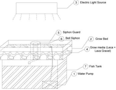
Figure 2.2. Media Bed design ... 5
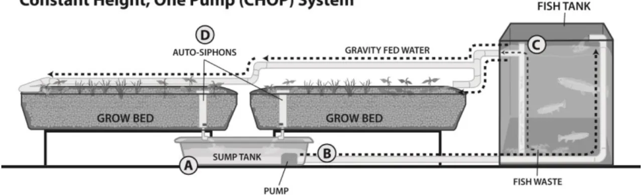
Figure 2.3. Constant Height One Pump System ... 6
Figure 2.4. Typical Hydroponic NFT design ... 7
Figure 2.5. Typical Hydroponic DWC design. ... 8
Figure 2.6. Two Pump system. ... 9
Figure 2.7. Indexing/Sequencing Valve. ... 9
Figure 2.8. Travis Hughley’s Barrelponic system ... 10
Figure 2.9. Example of a hybrid aquaponic system, combining DWC and Media Beds. ... 11
Figure 2.10. Example of a vertical aquaponics set-up, using a Media Bed system design ... 11
Figure 2.11. Aquaponicals Education Set, a desktop sized aquaponics system... 14
Figure 3.1. System 1 Overview ... 18
Figure 3.2. System 2 Overview ... 18
Figure 3.3.System 3 Overview ... 19
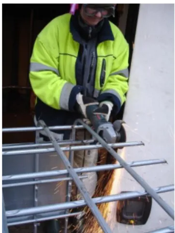
Figure 3.4. Cutting the IBC metal frame where the grow bed will rest ... 20
Figure 3.5. Evolution of the Indoor aquaponics system (System 1) ... 21
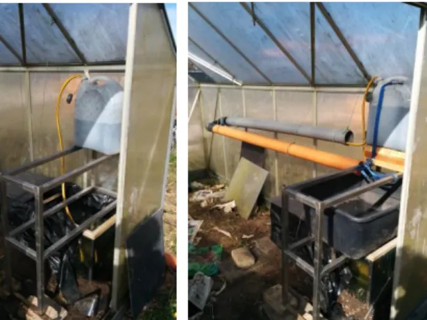
Figure 3.6. NFT pipes and DWC reservoir placement ... 22
Figure 3.7. NFT pipe holes with a diameter of 8 cm and spaced 25 cm from one another ... 22
Figure 3.8. Evolution of the Greenhouse aquaponics system (System 2) ... 23
Figure 3.9. Tower support structure in the DWC water reservoir ... 24
Figure 3.10. From left to right: Cutting the IBC, drilling the grow bed support and final assembly ... 24
Figure 3.11. Media layering technique ... 25
Figure 3.12. Greenhouse human urine-based aquaponic system overview ... 25
Figure 3.13. Greenhouse human urine-based aquaponic system overview ... 26
Figure 3.14. Commercial ammonia used (24,5%) ... 27
Figure 3.15. Example of the aged urine used for cycling and maintaining the greenhouse human urine-based aquaponics system (System 3) ... 28
Figure 3.16. From left to right: JBL test kits for ammonium/ammonia, nitrite and nitrate ... 28
XII
Figure 3.18. Cycling parameters of total ammonia nitrogen, nitrite and nitrate in the greenhouse
aquaponics system (System 2) through a period of one month ... 29
Figure 3.19. Cycling parameters of total ammonia nitrogen, nitrite and nitrate in the greenhouse human urine-based aquaponics system (System 3) through a period of about one month ... 30
Figure 3.20. From left to right: Liquid Iron Chelated and SM6 Seaweed Extract ... 31
Figure 3.21. Comparison of a strawberry plant with Iron deficiency (left) from the greenhouse aquaponics system, and a strawberry plant without Iron deficiency (right) from the greenhouse human urine-based aquaponic system ... 32
Figure 4.1. Commercial fish feed added to the indoor and greenhouse aquaponic systems (left) and aged urine added to the greenhouse human urine-based aquaponic system (right) ... 35
Figure 4.2.Example of colorimetric results from all the parameters tested.. ... 35
Figure 4.3. Evolution of TAN, NO2-, and NO3- on a starting biofilter of a Recirculating Aquaculture System (Molleda, 2007). ... 36
Figure 4.4. Evolution of Total Ammonia Nitrogen concentration in System 1. ... 37
Figure 4.5. Evolution of nitrite concentration in System 1. ... 38
Figure 4.6. Evolution of nitrate concentration in System 1. ... 38
Figure 4.7. Evolution of phosphate concentration in System 1. ... 39
Figure 4.8. Evolution of oxygen concentration in System 1. ... 39
Figure 4.9. Evolution of Total Ammonia Nitrogen concentration in System 2. ... 40
Figure 4.10. Evolution of nitrite concentration in System 2. ... 40
Figure 4.11. Evolution of nitrate concentration in System 2. ... 41
Figure 4.12. Evolution of phosphate concentration in System 2. ... 41
Figure 4.13. Evolution of oxygen concentration in System 2. ... 42
Figure 4.14. Evolution of Total Ammonia Nitrogen concentration in System 3. ... 42
Figure 4.15. Evolution of nitrite concentration in System 3. ... 43
Figure 4.16. Evolution of nitrate concentration in System 3. ... 43
Figure 4.17. Evolution of phosphate concentration in System 3. ... 44
XIII
Figure 7.1. Evolution of temperature in the Indoor Aquaponics System. ... 58
Figure 7.2. Evolution of pH in the Indoor Aquaponics System. ... 58
Figure 7.3. Evolution of Total Ammonia Nitrogen in the Indoor Aquaponics System. ... 59
Figure 7.4. Evolution of Nitrite in the Indoor Aquaponics System. ... 59
Figure 7.5. Evolution of Nitrate in the Indoor Aquaponics System ... 60
Figure 7.6. Evolution of Temperature in the Greenhouse Aquaponics System. ... 60
Figure 7.7. Evolution of pH in the Greenhouse Aquaponics System. ... 61
Figure 7.8. Evolution of Total Ammonia Nitrogen in the Greenhouse Aquaponics System. ... 61
Figure 7.9. Evolution of Nitrite in the Greenhouse Aquaponics System. ... 62
Figure 7.10. Evolution of Nitrate in the Greenhouse Aquaponics System. ... 62
Figure 7.11. Evolution of Temperature in the Greenhouse Human Urine-Based Aquaponics System. .... 63
Figure 7.12. Evolution of pH in the Greenhouse Human Urine-Based Aquaponics System. ... 63
Figure 7.13. Evolution of Total Ammonia Nitrogen in the Greenhouse Human Urine-Based Aquaponics System. ... 64
Figure 7.14. Evolution of Nitrite in the Greenhouse Human Urine-Based Aquaponics System. ... 64
XV
Table of Tables
Table 3.1. Average temperature in degrees Celsius in Hörby A station (station number 5353) between
1961 and 1990 ... 16
Table 4.1. Concentration of the tested parameters in the farm’s water well ... 37 Table 4.2. Literature parameter values by a few authors for aquaculture and recirculating aquaculture
systems. The parameter with an asterisk (*) indicates that it cannot be directly compared with the case study results ... 45
Table 4.3. Literature parameter values by a few authors for aquaculture and recirculating aquaculture
systems after applying an approach for the most demanding values from a hypothetical regulatory point of view. The parameter with an asterisk (*) indicates that it cannot be directly compared with the case study results ... 46
Table 4.4. Comparison between reference values found in literature with the case study values from both
the indoor and the greenhouse aquaponic systems (Systems 1 and 2 respectively) . Values with an asterisk (*) indicate the case study results were inferior than the reference values. Bolded values indicate how a certain system performed better than the other in each parameter ... 46
Table 4.5. Literature parameter values for urine composition of separated fresh urine (1),
source-separated stored urine (2), and source-source-separated urine after treatment (3). The parameters with an asterisk (*) indicate a special condition relevant to the comparison between authors. ... 48
Table 4.6. Comparison between reference values found in literature for urine composition of fresh urine,
source-separated urine, stored urine, and after treatment applying an approach for the most demanding values from a hypothetical regulatory point of view with the case study values from the greenhouse human urine-based aquaponic (System 3). The System 3 values with an asterisk (*) indicate the case study results were inferior to the reference values ... 49 Table 4.7. Comparison between nutrient percent removal found in literature with the nutrient percent
removal of the greenhouse human urine-based aquaponic system ... 50
Table 7.1. Recorded data from the commercial test kits concerning Total Ammonia Nitrogen, Nitrite,
XVII
Abbreviation List
BOD – Biological Oxygen Demand CHOP – Constant Height One Pump
CHIFT-PIST – Constant Height in Fish Tank - Pump in Sump Tank COD – Chemical Oxygen Demand
DWC – Deep Water Culture IBC – Intermediate Bulk Container LECA – Light Expanded Clay Aggregate NFT – Nutrient Film Technique
1 1. Introduction
1.1. Conceptual framework of thesis
Fresh water is one of the most precious resources for the survival of the human species. It is used every day for personal needs such as drinking, hygiene, cooking and sanitation, for agriculture in the form of irrigation, for energy production and for industrial purposes. The total percent of fresh water accessible for direct human use is less than 1% of all the worldwide water sources (University of Michigan, 2006), yet its use continues to increase as population and demand increases, with projections of 9,6 billion people by the year 2050, compared to the 7,2 billion people of mid-2013 (United Nations, 2013). Considering the agricultural use of water alone, there will be an increase in global consumption demand of 19% by 2050 (UNESCOPRESS, 2012).
Not only does water benefit humans directly, but it also supports other species in oceans and seas across the Earth necessary for human food production. To the extent that the current increase in population growth and pollution has occurred, the pressure on the nearby water resources has declined the available fish stocks (Vince, 2012). Since agriculture is the human activity with the biggest consumption of fresh water annually, contributing to 92% of water use (Hoekstra & Mekonnen, 2012), the stress factors mentioned above will also greatly restrict future food production. Sustaining future human activities, at an increasing human population growth and consumption, might be incompatible with fresh water availability.
Facing these facts will lead to the conclusion that human water use and pollution must be greatly reduced, since it can jeopardize human survival in the near future. In this regard, water and wastewater treatment technology, new efficient uses of water in agriculture, and other technologies will play key roles in preventing these issues.
Currently, the treatment of wastewater from humans and from fish farming activities such as aquaculture require a high amount of energy and resources in transporting, separating and treating the waste. These treatments often require channeling vast amounts of water to centralized treatment plants and discarding useful nutrients in the process, despite opportunities for nutrient recycling (Keller, 2012). At the same time, in agriculture most farming methods are inefficient in their irrigation methods, for example though conventional flood irrigation which loses 40% to the water table and through evaporation (Prins & Brouwer, 1989). Many of the nutrients currently used in agriculture are produced unsustainably by relying heavily in fossil fuels and scarce resources (Sims, 2011), and often ignoring the potential of nutrient recycling
(Refsgaard et al, 2005).
2 1.2. Thesis goals
This thesis will deal with describing what aquaponics is, its potential applications and the underlying biological processes. It will also describe how to dimension a variety of aquaponic systems and how they compare with current aquaculture wastewater treatments, as well as source-separated human urine treatment in wastewater treatment plants. Understanding how an aquaponic system works, its requirements and limitations will play a key role in assessing how such systems will help solve some of the problems outlined in the first sub-chapter. Detailing the building process of these systems, the calculations and assumptions will enable a full technical understanding on how to build these systems in similar conditions to ensure reproducibility of the results.
Finally, comparing the treatment potential of aquaponics systems in regards to conventional recirculating aquaculture filtration systems and separate human urine treatment in wastewater treatment plants will enable an understanding of the advantages and disadvantages of aquaponic systems as a new method for water treatment. The added benefit of simultaneous food production in these systems will also be considered.
1.3. Thesis structure
3 2. General considerations
2.1. Definition of Aquaponics, Aquaculture and Hydroponics
Aquaponics can be defined as “The cultivation of fish and plants together in a constructed,
recirculating ecosystem utilizing natural bacterial cycles to convert fish waste to plant nutrients. This is an environmentally friendly, natural food-growing method that harnesses the best attributes of aquaculture and hydroponics without the need to discard any water or filtrate or add chemical fertilizers” (Bernstein, 2013).
In this context, Aquaculture refers to the farming of aquatic organisms with human intervention
to improve production (FAO1, 2014). On the other hand, Hydroponics refers to growing plants
without soil, where the nutrient source is either a nutrient solution or nutrient enriched water (Jones, 2005). Aquaponics is therefore an attempt at converting the waste of one farming method into the nutrient input of another.
2.2. Aquaponics and aquaculture wastewater
Farming organisms such as fish in an aquaculture environment requires that the waste is removed from the environment periodically. Given that an aquaculture environment is not integrated in an ecosystem, the waste has nowhere to go, resulting in build-up which will kill the organisms if it is not actively removed.
2.2.1. Waste water from Aquaculture
The practice of aquaculture with fish as an example, leads to a diverse waste water composition. This waste can be in both solid form (fish carcasses, viscera, skin and heads) and liquid form (washing and cleaning water discharge, blood-water from drained fish storage tanks and brine)
(FAO2, 2014). Some of the parameters used in assessing the composition of aquaculture waste
water include: solids content, pH, temperature, odor, organic matter, biochemical oxygen demand (BOD), chemical oxygen demand (COD), oil and grease content, nitrogen and
phosphorous content (FAO2, 2014).
Of these parameters, nitrogen in the form of ammonia is considered to be the second most
important after oxygen, as it is the natural byproduct of fish metabolism (Francis-Floyd et al,
1996). A simple chemical explanation of ammonia is proposed by Francis-Floyd et al in their
1996 Ammonia in Aquatic Systems: “In water, ammonia occurs in two forms, which together are
called total ammonia nitrogen, or TAN. Chemically, these two forms are represented as NH4+
and NH3. NH4+ is called ionized ammonia because it has a positive electrical charge, and NH3 is
called un-ionized ammonia (UIA) because it has no charge. This difference is important to
know because NH3, un-ionized ammonia, is the form more toxic to fish”.
Ammonia in itself presents no problem in simple flow-through systems; however in common recirculating systems a biofilter and regular parameter observations are required (Molleda, 2007). Even with a microbe-based biofilter, effluents from recirculating aquaculture systems have high nutrient concentration, reaching >200mg/L nitrate nitrogen and 20-30 mg/L in mean
total phosphorus (Yeo et al, 2004). These nutrients are high enough to support typical
hydroponic plant production (Resh, 1989).
2.2.2. Aquaponic biological processes - The nitrogen cycle
There are several nutrient cycles occurring in an aquaponic system, however the most studied and generally understood one is the nitrogen cycle, occurring at the biofilter level. In this cycle,
nitrogen takes three main forms: ammonia (NH4+ or NH3), nitrite (NO2) and nitrate (NO3). An
explanation of the nitrogen cycle is proposed by Tyson et al in their 2004 Reconciling water
quality parameters impacting nitrification in aquaponics: The pH levels. This scientific paper
states that: “Ammonia is the main excretion product from fish. Both un-ionized ammonia and
nitrite can be toxic to fish at very low levels. In the process of nitrification, certain autotrophic
4 oxidize nitrite to nitrate. The overall reaction of nitrification and cell biomass formation can be written as:
Nitrosomonas
55 NH4+ + 5 CO2 + 76 O2→ C5H7NO2 + 54 NO2- + 52 H2O + 109 H+
Nitrobacter
400 NO2- + 5 CO2 + NH4+ + 195 O2 + 2H2O → C5H7NO2 + 400 NO3- + H+
The nitrogen transformation eliminates ammonia from the water. Nitrate is not toxic to fish except at very high levels and is the primary source of nitrogen for plants in hydroponic systems”.
There are several strains of bacteria that take part of the nitrification process, but the ones
believed to be more prominent are Nitrosomona and Nitrobacter. Ammonia removal from the
water is a crucial step in such a recirculating system, as it allows the water quality to decrease in toxicity for the fish, removing the need for constant water changes. A simple overview of the nitrogen cycle can be viewed in Figure 2.1:
Figure 2.1. The Nitrogen cycle in an aquaponic system. Adapted from TilapiaHouse.com, by Tilapia
5 Apart from biological filtration, solids filtration in an aquaponic system is also essential in
achieving proper water quality for fish and plants (Tyson et al, 2004). Solids filtration generally
consists of both the mineralization of the solids into plant available nutrient forms, as well as the
mechanical filtration of solids (Lennard1, 2012). Mineralization can either be aerobic or
anaerobic, but it is regarded that aerobic solids mineralization should be encouraged in
aquaponic systems (Lennard1, 2012).
2.3. Types of Aquaponic systems 2.3.1. Media Bed
A media bed aquaponic system is one of the most common setup of aquaponic systems due to its simplicity of assembly. At its most basic form, it consists of a water reservoir or fish tank, a grow bed, a water pump and a return pipe or hole. The water reservoir or fish tank is where fish are kept, fed and harvested from; the grow bed is where plants are grown and harvested in a soilless media, serving also as a mechanical filter and a biofilter; the water pump will transport water from the water reservoir to the grow bed; and lastly the return pipe or hole will return clean water to the water reservoir.
Benefits of this system design include: removal of solids from the water reservoir, breakdown of solids, biofiltration, and better plant root support. It also has familiarity with traditional soil gardening as there is a media where plants are grown. A simple schematic diagram representing this system can be seen in Figure 2.2:
Figure 2.2. Media Bed design. Adapted from Aquaponic Gardening: A step-by-step guide to raising
vegetables and fish together, by Sylvia Bernstein, 2013. Copyright 2013 by Sylvia Bernstein
Media can consist of materials such as expanded clay aggregate, lava gravel, expanded shale, or rocks. The media should be inert, not decompose, and not alter the chemical composition of the water. The media should also be free from potential release of toxins harmful to the plants, fish, and nitrifying bacteria.
A media bed aquaponic system commonly operates under a flood and drain cycle (also known as ebb and flow). Under this principle, the grow bed is flooded with water and then allowed to drain, either through the use of a pump timer or a siphon. A siphon, autosiphon, or bell siphon is a simple technology which allows water to be drained faster than the incoming flow from the pump, by covering the standpipe with a sealed tube or “bell”. This bell has holes that only allow water and not air to enter after a certain level, and as the level of water rises it pushes the remaining air trapped inside through the standpipe. Eventually the whole system is filled of water which creates a flush-like mechanism and will drain the water quickly until it reaches the
6 Looking at the basic aquaponics system design (Figure 2.2), water level in the water reservoir will change as flood and drain cycles occur. With the addition of more grow beds, the water level difference in the reservoir may be stressful to the fish (Bernstein, 2013). This has led to some design suggestions on the addition of a third component: a sump tank.
A sump tank, now the lowest level of the system, is essentially a second water reservoir where the pump is located, allowing for a constant water level in the fish tank. Having the pump away from direct contact with fish waste and solids may also prevent clogging of the pump. However other variations also include fish in the sump tank, allowing for greater stocking capacity. This design is commonly referred to as CHOP (Constant Height One Pump) or CHIFT-PIST
(Constant Height In Fish Tank – Pump in Sump Tank) by aquaponic enthusiasts. A downside to
this design is the need for the fish tank to be higher than the grow beds, so water can be transported by gravity without the need for a second pump. A simple schematic representing this new system is presented in Figure 2.3.
Figure 2.3. Constant Height One Pump System. Adapted from Aquaponic Gardening:
A step-by-step guide to raising vegetables and fish together, by Sylvia Bernstein, 2013. Copyright 2013 by Sylvia Bernstein
A media bed aquaponic system can also operate under a continuous flood/flow design. Without the use of a pump timer or siphon, the grow bed as well as the fish tank will have a constant level of water. It is believed that one advantage of flood and drain cycle versus continuous flood/flow is the delivery of oxygen rich air to the roots of the plants (Bernstein, 2013). On the other hand, continuous flood/flow in a media bed design may cause plant roots to become saturated with water, without access to enough oxygen, and areas of the grow bed to become stagnant and anaerobic.
2.3.2. NFT - Nutrient Film Technique
7
Figure 2.4. Typical Hydroponic NFT design. Adapted from Sdhydroponics.com, by
Sunny Datko 2012, Retrieved from
http://sdhydroponics.com/resources/articles/gardening/how-to-grow-hydroponically-%E2%80%93-overview-of-grow-systems. Copyright 2014 by San Diego Hydroponics & Organics
In hydroponics the water in the system already contains all necessary dissolved nutrients. This is in contrast to aquaponics, where an additional filter is required to perform the mechanical filtration and mineralization of fish solid waste, as well as the bio-filtration. The aquaponic filter thus allows a large surface area for nitrifying bacteria cells to colonize (DeLong & Losordo, 2012). The product of the bacteria metabolism results in nutrient-rich water that then flows through the channels, returning in the end to the fish tank.
While it is easy to plant, harvest and maintain an NFT system, some drawbacks have been discussed. These include little buffering against interruptions in the flow of water, e.g. a power outage, high water temperature fluctuations and blockages in water flow due to dead detached roots. NFT may also be limiting in the types of plants suitable, as some will have big invasive root systems which may be too heavy for the lightweight channels.
In a study comparing different hydroponic sub-systems in an aquaponic test system, overall results suggested that a NFT system was less efficient in removing nutrients from the water as well as less efficient in producing plant biomass (Lennard & Leonard, 2006), when compared to a Media Bed System or a Deep Water Culture system.
2.3.3. DWC - Deep Water Culture
8
Figure 2.5. Typical Hydroponic DWC design. Adapted from Contemporary Food
Lab.com, by Vanessa Gürtler 2014, Retrieved from . Copyright 2014 by Contemporary Food Lab
As with an NFT aquaponics system, an additional filter is required to perform the mechanical filtration and mineralization of fish solid waste, as well as the bio-filtration.
A DWC system is a common design found in commercial aquaponics. It is generally considered to benefit from a raft-covered water reservoir, as it makes the system less prone to water temperature and pH fluctuations. It also allows for excellent root development due to the easy access to oxygen in the water. Compared to an NFT system, it also provides buffering against interruptions in the flow of water. Visual access to the roots by lifting the raft systems allows for easy plant health monitoring. However, due to the lightweight nature of the rafts or trays, large plants may be very difficult to support. Therefore, the most common DWC plants include salad greens and herbs.
2.3.4. Other Systems
Aquaponics allows for a diverse amount of systems and designs based on the Media Bed, Nutrient Film Technique and Deep Water Culture designs.
9
Figure 2.6. Two Pump system. Adapted from Aquaponic Gardening: A step-by-step
guide to raising vegetables and fish together, by Sylvia Bernstein, 2013. Copyright 2013 by Sylvia Bernstein
Another design improvement uses an indexing valve (Figure 2.7) to sequentially irrigate several grow beds. With this valve, the number of grow beds can be increased without needing to buy a bigger fish tank.
Figure 2.7. Indexing/Sequencing Valve. Adapted from AquaponicLynx.com, by
Aquaponic Lynx LLC 2014, Retrieved from
http://www.aquaponiclynx.com/products/aquaponic-systems-and-components/plumbing-and-valves/aquaponics-indexing-valves. Copyright 2014 by Aquaponic Lynx LLC
10
Figure 2.8. Travis Hughley’s Barrelponic system. Adapted from npecom.com, by Jeff
2013, Retrieved from http://npecom.com/rootz/save-money-on-gardening-supplies/. Copyright 2014 by Travis Hughley
11
Figure 2.9. Example of a hybrid aquaponic system, combining DWC and Media Beds. Adapted from Aquaponic Source.com, by Japan Aquaponics 2012, Retrieved from http://community.theaquaponicsource.com/forum/topics/aquaponics-in-japan-feedback-on-design-for-community-group. Copyright 2014 by Sylvia Bernstein
Aquaponic systems may also take advantage of vertical farming as it requires less horizontal growing area, ideal for urban farming. Most vertical aquaponic designs are a variation of a Media Bed System, which uses a soilless media to grow the plants. In a vertical design, priority is given to lightweight media such as expanded clay aggregate to prevent the structure from
collapsing under its own weight (Figure 2.10).
Figure 2.10. Example of a vertical aquaponics set-up, using a Media Bed system
12 2.4. Aquaponics and human urine treatment
2.4.1. Human urine composition
Human urine is an aqueous solution secreted by the kidneys which consists primarily of water. Remaining main components include urea and dissolved ions such as chloride, sodium, potassium, and creatinine (Putnam, 1971). Urine can provide a plant-available source of nitrogen by a process known as ammonia volatilization from urea. In this process, urease catalyzes the hydrolysis of urea to unstable carbamic acid, followed by a rapid decomposition of
carbamic acid to form un-ionized ammonia (NH3) and carbon dioxide (Tisdale et al, 1985). The
above description can be expressed as the following chemical reaction, stated by (Brady & Weil, 2001):
(NH2)2CO + H2O NH3 + H2NCOOH → 2NH3 (gas) + CO2 (gas)
The formed ammonia might escape to the atmosphere unless it reacts with water to produce
ionized ammonia (NH4+), according to the following reaction:
NH3(gas) + H2O → NH4+ + OH
-This reaction is important to note since ionized ammonia is a plant available source of nitrogen while un-ionized ammonia is not (Brady & Weil, 2001).
It is worth referring that urine is generally considered as fertilizer and for aquaponic use only when it is acquired from a healthy individual without any current illness or infection, and under no type of medication. This requirement can create some limitations for the collecting of source-separated urine and its further treatment.
2.4.2. Contemporary aquaponic uses of human urine
Discussion of the use of urine in aquaponic systems can be traced back to online aquaponic discussion communities, one of the more popular communities being Backyard Aquaponics. By some aquaponics enthusiasts, urine has been considered as having several benefits since it can allow for an ammonia source to function as the base of bacterial population for the aquaponic system, a process commonly referred to as “cycling”. A human source of ammonia can also be
used in separate tanks to grow duckweed (Araceaelemnoideae), as an alternative source of fish
food (Leng et al, 1995).
More interesting however, is the possibility of creating an aquaponics system without any fish, using human urine as the only source of ammonia. There is no standard name for this sort of practice, although common terms found online include “urineponics” and “peeponics”. A human urine aquaponic system grants some liberties in the water reservoir tank size, as there is no fish and no overstocking limit to restrict the ammonia source. Therefore, water reservoir tanks can be much smaller, and the amount of ammonia added is slightly more controllable when compared with ammonia from fish waste. On the other hand, only fresh produce is grown as opposed to the additional growing of fish in traditional aquaponics systems. Thus this urine-based aquaponic system serves a different purpose: a waste water treatment and nutrient recovery system rather than a constructed ecosystem.
In some of the testimonies and experiments of aquaponic online communities, the methodology
seems to be based on the research conducted by Pradhan et al on the use of urine as a
plant-fertilizer. According to their methods, urine is first aged to kill any possible hazardous pathogens that may contaminate the produce. Sterilizing the urine helps minimize the risk of any possible health problem, since it leads to very few detected microorganisms such as fæcal
coliforms, clostridia, enterococci and coliphages (Pradhan et al, 2007).
There is mixed research suggesting that urine is sterile until it reaches the urethra (Madigan &
Brock, 2009), while other suggests that urine is not sterile even in the bladder (Hilt et al, 2013).
13 using urine mostly depends on cross-contamination by fæces (Höglund, 2001). Considering urine may not be sterile, bacterial population can be reduced by allowing the urea to be degraded by the urease enzyme to ammonium and water. It has been observed that allowing the urine to degrade until it reached a pH level exceeding 9 will result in bacterial reduction
(Pradhan et al, 2007). Recommended storage time is 6 months for the use of urine as fertilizer in
soil in colder climates (Jönsson et al, 1997), however it should be sufficient to wait until the
target pH level has been reached since a recommended storage time of 6 months assumes the
stored urine to be subject to colder climate outdoor temperatures (Pradhan et al, 2007).
2.5. State-of-the-art in Aquaponics 2.5.1. Existing applications
Aquaponic systems can currently be found in a variety of applications. These include commercial systems, urban farming in backyards and apartments, and some educational systems and events. Commercial aquaponic systems typically strive to profit from both the hydroponic as well as the aquaponic components, as grown fish and plants can be sold for a premium price with marketing efforts (Goodman, 2011). Out of the two products, plants tend to be more profitable than fish (Bernstein, 2013). However, there is few existing literature on the financial sustainability of these commercial systems (Goodman, 2011).
While aquaponics businesses may strive to produce fish and vegetables commercially, some aquaponics businesses instead focus on selling systems and solutions. Even though some solutions are targeted for commercial systems, other designs include pre-fabricated backyard and home-scale systems for individuals and families. As a result of pre-fabricated systems for purchase and readily available information, aquaponic practice is spreading through urban environments (Brown-Paul, 2013).
14
Figure 2.11. Aquaponicals Education Set, a desktop sized aquaponics system. Adapted
from TheAquaponicStore.com, by TheAquaponicStore 2014, Retrieved from http://www.theaquaponicstore.com/Aquaponicals-Education-Set-p/tpdas003.htm. Copyright 2014 by The Aquaponic Source, Inc
2.5.2. Research & Development in the field
Most of the research and development in aquaponics has been done on the topic of how to design and operate aquaponics systems from a scientific and technical perspective. Research
may cover fish to plant ratios (Lennard2, 2012), Media Bed sizing (Lennard3, 2012), fish tank
shape and design (Lennard4, 2012) as well as comparison of three different types of aquaponic
sub-systems. Out of these sub-systems, the Media Bed system performed the best while the NFT performed the worst in both biomass gain and removing nutrients from fish culture (Lennard & Leonard, 2006).
Other research has studied the use of ornamental fish as a complementary species, concluding that while not suitable for commercial plant production alone, they would be a good addition to systems in temperate regions (Bathia, 2012). Additionally, a study on the impact on pH levels of aquaponic nitrification concluded that the optimal pH range should be between 6,5 and 7 for
optimal plant and fish growth (Tyson et al, 2004). Using geothermal energy to heat water in
aquaponic systems has also been studied, providing a successful case study of the use of waste heat for growing warm temperature aquaponic fish in Iceland (Sigurgísladóttir, 2011) and may provide new possibilities for temperate and cold regions. Factors affecting the economic sustainability of aquaponic systems were investigated, showing how system design affects
chemo-physical parameters, system stability and fish and plant production (Palm et al, 2014).
15 lettuce had significantly lower concentration of fæcal microorganisms and spoilage (Sirsat & Neal, 2013).
Some research has also looked into alternative fish food such as Black Soldier Fly larvae (Hermetia illucens), concluding that it can be used for aquaponic feeding, though processing it
into dehydrated ground meal will increase the quality of the feed (Stankus, 2013). A study comparing duckweed, soybean meal, rice bran and sorghum as alternative fish food sources found that sorghum and rice bran produced lower plant yields, while soybean meal yielded
better fish growth (Aguilera-Titus et al, 2014).
Concerning human urine based aquaponics, currently no research is found except for accounts in backyard experiments by aquaponic enthusiasts. These experiments include: water chemistry and Escherichia coli tests in a backyard human urine-based aquaponics system, growing
duckweed (Araceaelemnoideae) as fish food using human urine, and comparing plant growth in
16 3. Case Study
3.1. Location and Entity
A case study was performed with the company Grönare Stad AB. The enterprise was created in 2011 by Louise Lundberg, with the goal of sustainable city development. This includes urban farming, aquaponic systems, roof gardens, urban drainage and storm water management, as well as education in these topics.
The aquaponic systems developed for the case study were located at a small farm in Askeröd, part of the Hörby County, in the Skåne region of Sweden. The farm was acquired by the current
owners in 2007, and has 12 000 m2 of land. In the farm one of the systems was built in a boiler
room, which provides hot water all year round for the buildings, as well as heating for the main
house during the winter. Two other systems were built in a greenhouse with 10 m2, which had
been previously used for growing tomatoes in soil.
3.2. Climate characteristics of the region
Sweden has a cold climate, with the Skåne region having a temperate climate (CIESIN, 2007). According to data from the Swedish Meteorological and Hydrological Institute SMHI, Skåne
has the mildest temperature in Sweden, even with local differences (SMHI1, 2007). The
Swedish Meteorological and Hydrological Institute (SMHI) is a government agency that operates under the Ministry of the Environment, offering forecasts, statistics and climate studies. The SMHI presents average temperature data in degrees Celsius for specific measured periods of thirty years. This average temperature is taken throughout both day and night and results for a thirty year period are shown in Table 3.1.
Table 3.1. Average temperature in degrees Celsius in Hörby A station (station number
5353) between 1961 and 1990, adapted (SMHI1, 2007)
Month Period Jan Feb Mar Apr May Jun Jul Aug Sep Oct Nov Dec Year
Temp.
(ºC) 61-90 -1,6 -1,5 1,0 5,4 10,4 14,4 15,5 15,3 11,9 8 3,6 0,1 6,9
Despite having a milder temperature, the region of Skåne is still too cold for many plant species. The most common grown crops include potatoes, wheat, sugar beets, grains, winter wheat, and
plants suitable for oil production (Kyllmar et al, 2005) such as rapeseed. Various vegetables are
generally grown in greenhouses to survive the cooler temperatures. This is an important factor to consider when planning which plant species to cultivate in the aquaponic systems.
Concerning wind, southern Sweden experiences slightly stronger winds than the northern part of Sweden. The typical annual mean wind speeds in Sweden ranges between 2 and 5 m/s
(Achberger et al, 2005). Southern Sweden to the south of ≈58°- 60°N, which is the case of
Hörby, usually has higher annual means since the region is more directly exposed to winds from
the west and the southwest (Achberger et al, 2005). Absolute humidity (g water/m3) is highest
in the south of Sweden (SMHI2, 2013), with humidity values ranging between 4 g water/m3 to
11 g water/m3 depending on whether it is winter or summer, respectively (SMHI2, 2013).
Overall, the region of Skåne appears to have the best climate conditions for outdoor and greenhouse cultivation. However, outdoor temperatures are too cold for outdoor cultivation in soil and thus outdoor aquaponic cultivation of many vegetables. For this reason, the aquaponic systems were built in a greenhouse and in an indoor environment.
3.3. Economic and Demographic aspects of the case study
17 stores and at internet stores. The available budget of Grönare Stad AB for building the
aquaponic systems was set for 8 000 Swedish kronor (approximately 870 € on June 30th 2014)
for a one year period. The most expensive individual items included an IBC, several pumps and expanded clay aggregate bags for the grow beds.
During the period stated above, two positive income sources resulted from the aquaponic systems, in the form of guided tours of the systems and workshops concerning aquaponics. This enabled the Grönare Stad AB company to break even in the expected costs and to have some food production with almost no cost. The aquaponic systems will produce food for the owners and residents of the farm. These consist of a family of four, two adults and two children, with occasional volunteer farming assistants.
3.4. Existing limitations/restrictions
Limitations on the construction of the aquaponic systems were mostly of economic nature. Several contacts were made in hopes of negotiating a partnership. Meetings took place with some institutions, companies, and universities, however without success. As such, the financial resources for the materials came exclusively from the company Grönare Stad AB. The 8 000 Swedish kronor budget limit had an important impact in design decisions, as it encouraged the re-use of available materials. This also restricted the ability to purchase test kits for parameters other than the ones used to monitor the cycling process and limited the fish species considered. The chosen fish species were less expensive ornamental fish rather than edible varieties or species requiring additional water temperature heating. The budget limit also made it unfeasible to purchase existing commercial aquaponic and hydroponic materials as they are either too expensive to import to Sweden from abroad, or too expensive to buy in existing Swedish retail stores. Additionally, some of the building materials that had to be bought took some time to find, delaying the construction and assembly time.
Another important restriction was space as the greenhouse was only 10 m2. To maximize
growing space, small vertical farming towers were combined with the more common designs. The greenhouse height restricted the size of these towers to 0,8 m, which is less than ideal for being able to take advantage of vertical farming. After the aquaponics systems were built and operating, some of the vegetable growth made maintenance practices difficult, particularly in IBC based Media Bed systems. As aquaponics and especially human urine based aquaponic systems are a relatively new field of practice, theoretical and practical dimensioning guidelines from academic sources were hard to find. Most information available was found in communities of aquaponic enthusiasts or instruction books.
3.5. Dimensioning
3.5.1. General systems overview
Three systems were built in total. The systems range in complexity, from a simple Media Bed system to systems incorporating NFT, DWC and even vertical designs. The difference in complexity was chosen to test different designs in their ability to filter the fish waste or human urine, and in their capacity to grow plants.
18
Figure 3.1. System 1 Overview
The second system built is located in the greenhouse, and is a combination of a NFT system with a DWC system, coupled with two filters in a continuous flow cycle (System 2). The system has a fish tank where the water is pumped from and diverted into two parallel filters. These return the filtered water to a descending NFT pipe, which channels the water into a small DWC reservoir with a standpipe that delivers the water back to the fish tank. The filters are filled with
charcoal, which has a high surface area (Campbell et al, 2012) suitable for the colonization by
the bacteria in the biofilter, in addition to LECA. Incoming water to the filters can be regulated by a valve which controls the flow of water, allowing for the water level in both filters to be controlled. An additional air pump was placed to supply enough oxygen to the DWC component (Figure 3.2).
Figure 3.2. System 2 Overview
19 of the vertical farming component are running on a continuous flow cycle. Since the system runs on aged human urine, there are no fish in any part of the system. The overall system has a sump tank from which the water is pumped to twelve towers filled with LECA, and to the Media Bed component. The water drips into the towers through valves that allow for flow regulation, with eight of the towers being located on top of the DWC component and the remaining four being located on top of the Media Bed. The DWC component has a standpipe which allows for a constant water level and returns the overflow to the sump tank. The water from the four towers on top Media Bed component, as well as the water pumped from the sump tank, supplies water to the grow bed. Since the flow rate from these two sources was not enough to start the bell siphon automatically, an extra water pump was added in the water reservoir below the grow bed to recirculate the water. An overflow pipe on the water reservoir below the grow bed returns the water to the sump tank. As an additional oxygen source, an air pump provides air to two air stones, one on the DWC component and the other to the water reservoir below the grow bed (Figure 3.3).
Figure 3.3.System 3 Overview 3.5.2. Assumptions, Building and Calculations
Assumptions
For the building of Media Bed systems it is often suggested to follow a 1:1 ratio or 2:1 of volume occupied by the grow media in the grow bed to the water volume in the fish tank (Bernstein, 2013). However, other designs using an IBC ignore this suggestion, achieving ratios of 1:2 or 1:3 (Malcolm & Faye, 2011). As such, the main assumption followed when building Media Bed systems from IBC is the suggestion that all of the water volume should circulate through the grow bed within one hour (Bernstein, 2013), which requires a certain minimum pump flow rate. The Media Bed system used indoors (System 1) as well as the Media Bed component of the human-urine based aquaponics system in the greenhouse (System 3) were both built out of an IBC, and the instructions were adapted from Malcom & Faye’s 2011 IBC of Aquaponics Edition 1.0. In that document together with Bernstein’s 2013 Aquaponic Gardening, it is recommended that the grow bed has at least 30 cm of depth as a standard,
although there is no scientific research behind this recommendation (Bernstein, 2013).
20 increasing the surface area of the water body and thus the amount of gas exchange from the
water body to the atmosphere (Lennard5, 2012).
Siphon size and piping is dependent on the size of the bulkhead fitting, a device used to connect a pipe through a grow bed whole without leaking water. The recommended ratio of bell siphon
diameter to the standpipe drain is 2:1 (Fox et al, 2010), and was the minimum ratio followed.
The available materials found in stores resulted in a ratio of bell siphon diameter to the standpipe drain of 3:1.
The main design assumptions for the two more complex systems (System 2 and System 3) were to place more nutrient demanding plants in the biofilter (such as the grow bed and towers of System 3) or immediately after it (such as the NFT component of System 2). Less nutrient demanding plants would be placed immediately before the fish tank or the sump tank, in a DWC system. This was based from Lennard & Leonard’s 2006 A comparison of three different hydroponic sub-systems (gravel bed, floating and nutrient film technique) in an Aquaponic test system, where it was concluded that NFT and DWC systems were less able to support more
nutrient demanding plants with bigger root systems.
Building
The first aquaponics system built was the indoor Media Bed system (System 1) located in the boiler room of the farm. It was built out of an IBC and was adapted from the instructions of Malcom & Faye’s 2011 IBC of Aquaponics Edition 1.0. Construction began on February 12th
2014 and it was completed on March 3rd 2014, without any plants or fish added. The
construction included cutting the IBC and its metal frame from the bottom to a height of 70 cm. The end result is a fish tank with a volume of 1464,75 L (135 cm x 155 cm x 70 cm), and a grow bed with a volume of 627,75 L (155 cm x 135 cm x 30 cm) (Figure 3.4).
Figure 3.4. Cutting the IBC metal frame where the grow bed will rest. February 13th
2014
The lid of the IBC is located in the grow bed component, which was drilled to create a ⌀=3 cm
hole. A bulkhead fitting was placed in the hole to allow for the standpipe to be placed above as
well as to ensure a watertight seal of the grow bed. A white plastic pipe (⌀=3 cm) was cut to a
length of 35 cm and inserted through the bulkhead fitting, rising 20 cm from the bottom of the grow bed with the remaining 15 cm below the grow bed. This pipe serves as the standpipe and will regulate the maximum height of water the grow bed will have before the siphon begins. An
additional rubber connection (⌀=2,5 cm) was added at the bottom of the standpipe near the
21
The bell siphon was built from a ⌀=9 cm PVC pipe, cut to a height of 30 cm and with an airtight
lid placed on its top. The bell siphon had ⌀=0,5 cm holes drilled in the bottom 5 cm of the PVC
pipe to allow water inflow. The siphon guard, which serves as a physical protection of the bell
siphon from clogging with media, was cut from an orange plastic pipe (⌀=20 cm) to a length of
30 cm. The siphon guard also had slits cut to ensure water inflow, but small enough to prevent media from flowing through.
The media, consisting of LECA and lava gravel, was rinsed with tap water and mixed in the grow bed to a height of 20 cm. The lack of layering between these two types of media resulted in the LECA to float as the water level increased, resulting in some occasional siphon clogging as well as plant submersion. Until the LECA became soaked enough to stop rising with the
water level, an overflow exit was built consisting of a ⌀=3 cm hole with a bulkhead fitting, a
protective net, and a 90° pipe with another 40 cm length pipe.
Regular tap water was added to a height of 55 cm in the fish tank, corresponding to 1150 L of water. An available pond pump with a flow rate of 7 600 L/h was inserted in the bottom of the
fish tank, and a ⌀=4 cm hose connected the pump to the top of the grow bed. The final step was
adding 400 W High Pressure Sodium lamps at a height of 60 cm to the media level in the grow bed (Figure 3.5).
Figure 3.5. Evolution of the Indoor aquaponics system (System 1). March 3rd 2014 -
July 7th 2014
The second aquaponics system built (System 2) was the NFT and DWC combined system
located in the farm’s greenhouse. It was built using materials available at the farm such as an
aquarium, a container, pipes, and barrels. Construction began on April 1st 2014 and it was
completed on April 4th 2014, without any plants or fish added. The fish tank used had a volume
of 220 L (110 cm x 40 cm x 50 cm), the two filters have a combined volume of 60,2 L (35,2 L + 25 L), and the DWC reservoir had a volume of 147 L (70 cm x 70 cm x 30 cm). The total water volume in the fish tank with 40 cm of water height and DWC reservoir with 20 cm of water height corresponds to 274 L (176 L + 98 L).
Construction began by digging an approximately 15 cm deep pit in the greenhouse soil to place the fish tank in. A steel framed table was placed on top of the fish tank, with the supports resting on concrete bricks that were placed on both sides of the pit near the fish tank. In the middle of the steel framed table there is enough space and support to place the DWC reservoir, which had
a ⌀=3 cm hole drilled where a bulkhead fitting was inserted. A ⌀=3 cm white plastic pipe 30 cm
22
Figure 3.6. NFT pipes and DWC reservoir placement. April 1st 2014 – April 3rd 2014
Initially only the 35,2 L filter was placed on the top part of the steel framed table and above the DWC, but later on a second filter with an additional 25 L of total volume was placed at an
elevated height next to the first filter. A ⌀=12 cm PVC pipe with a length of 200 cm attached to
the greenhouse wall with a slope of 4%. An additional ⌀=10 cm plastic pipe with a length of
240 cm was placed slightly further away from the greenhouse wall with a slope of 6,25%. The tip of the 240 cm plastic pipe rests on the edge of the DWC reservoir. The NFT pipes used had a
total of sixteen ⌀=8 cm holes drilled into them, separated from one another by 25 cm – 30 cm of
distance to place net pots (Figure 3.7).
Figure 3.7. NFT pipe holes with a diameter of 8 cm and spaced 25 cm from one
another. April 4th 2014
The filters were filled with rinsed LECA and charcoal, and later covered in a black plastic to prevent excessive algae growth. The individual system components were connected by first
placing a 1 750L/h pump in the fish tank, with a ⌀=1,5 cm garden hose connecting the pump to
the first filter and continuing to the second filter through a garden hose Y connector, to a height of 150 cm. The hose enters the filter container through an open lid at the top and exits through
an exit valve at the bottom, which has a ⌀=1,5 cm garden hose connecting it to the NFT 200 cm
pipe.
Both NFT pipes were connected to one another through a rubber inner tube tire, which was washed prior to use to remove any existing contaminants. The ends of the rubber inner tube tire are secured to each pipe with metal pipe holders. In the DWC reservoir, a 24,5 L Styrofoam
board (70 cm x 70 cm x 4 cm) was placed with thirteen ⌀=8 cm holes drilled into them, twelve
23 covered with pond liner on the sides, and a lid was placed over the fish tank to prevent an increase in algae growth due to excess sunlight (Figure 3.8).
Figure 3.8. Evolution of the Greenhouse aquaponics system (System 2). March 4th 2014 – June 9th 2014
The third system built was the human urine-based aquaponic system (System 3) located in the farm´s greenhouse, combining a Media Bed, towers and a DWC component. It was built using a repurposed aquaponic grow bed as the DWC reservoir, two plastic barrels, an IBC and several
PVC pipes and recycled plastic towers available at the farm. Construction began on April 31st
2014 and it was completed on May 9th 2014, without any plants or fish added. The main
components include a sump tank made of two connected barrels, a DWC water reservoir, a Media Bed water reservoir and a grow bed.
The sump tank used had a combined volume of 368 L (214 L + 154 L), the DWC water reservoir had a volume of 370,5 L (190 cm x 65 cm x 30 cm), the grow bed had a volume of 627,75 L (155 cm x 135 cm x 30 cm), and the Media Bed water reservoir had a volume of 1 464,75 L available (135 cm x 155 cm x 70 cm). The total water volume in the system is 1 746,6 L (136,1 L + 10, L + 247 L + 1 255,5 L), where the water height of the connected sump tanks is 35 cm and 28 cm, 20 cm in the DWC water reservoir, and 60 cm in the Media Bed water reservoir.
Construction began by repurposing an old aquaponic grow bed built from recyclable plastic towers into the DWC water reservoir. The previous media was rinsed and removed, the existing
pond liner was washed and a new ⌀=3 cm standpipe with 20 cm of height from the bottom of
the DWC water reservoir was added. This standpipe had a total length of 200 cm and was placed directly above the sump tank where the pump would be located. Three recycled plastic towers were cut to a height of 20 cm and placed in the DWC water reservoir and underneath a plastic fit for the support of the growing towers (Figure 3.9). The plastic fit was 190 cm in
length and had been drilled with ⌀=0,5 cm holes every 10 cm for drainage of the water coming
24
Figure 3.9. Tower support structure in the DWC water reservoir. April 16th 2014
The total number of towers used above the water reservoir was eight, four made from ⌀=8 cm
PVC pipe and four made from recyclable plastic. All towers have a height of 70 cm, and the
four towers made from recyclable plastic had four ⌀=5 cm holes drilled for future plant
placement. The towers were all filled with LECA as it was the lightest type of media available. The construction of the Media Bed component followed the same steps and used the same materials as the construction of the indoor aquaponic system in the boiler room of the farm (Figure 3.10).
Figure 3.10. From left to right: Cutting the IBC, drilling the grow bed support and final
assembly. March 31st 2014 – April 16th 2014
The media added on the grow bed was added in layers of LECA and lava gravel to ensure enough weight on the LECA to prevent it from rising with the water level (Figure 3.11). On top of the final layer of LECA, a plastic fit with a length of 155 cm was placed and four growing
towers were positioned, comprising of two ⌀=8 cm PVC towers and two recyclable plastic