Bruno Miguel de Figueiredo Ramos
Licenciado em Ciências da Engenharia Electrotécnica e de Computadores
Lightly synchronized Multipacket Reception in
Machine-Type Communications Networks
Dissertação para obtenção do Grau de Mestre em
Engenharia Electrotécnica e de Computadores
Orientadores: Luis Filipe Lourenço Bernardo, Pr.Dr, FCT-UNL
Rui Miguel Henriques Dias Morgado Dinis , Pr.Dr, FCT-UNL
Júri
Presidente: Rodolfo Alexandre Duarte Oliveira, Prof. Dr., FCT-UNL Arguente: Nuno Manuel Branco Souto, Prof.Dr., ISCTE-IUL
Lightly synchronized Multipacket Reception in Machine-Type Communica-tions Networks
Copyright © Bruno Miguel de Figueiredo Ramos, Faculdade de Ciências e Tecnologia, Universidade NOVA de Lisboa.
A Faculdade de Ciências e Tecnologia e a Universidade NOVA de Lisboa têm o direito, perpétuo e sem limites geográficos, de arquivar e publicar esta dissertação através de exemplares impressos reproduzidos em papel ou de forma digital, ou por qualquer outro meio conhecido ou que venha a ser inventado, e de a divulgar através de repositórios científicos e de admitir a sua cópia e distribuição com objetivos educacionais ou de inves-tigação, não comerciais, desde que seja dado crédito ao autor e editor.
Este documento foi gerado utilizando o processador (pdf)LATEX, com base no template “unlthesis” [1] desenvolvido no Dep.
A c k n o w l e d g e m e n t s
I want to start by thanking Prof. Dr. Luís Bernardo, the main reason this dissertation was made possible. I was really lucky to have him as my adviser. He was extremely patient with me and all my technical flaws, in times of extreme pressure, his guidance made things seem easy when they were not.
I’d like to thank the entire telecommunication group. Since my first year at the uni-versity that my passion for telecommunications began to grow, and the lectures from this group of professors inspired me alot.
This work was supported byFundação para a Ciência e a Tecnologia (FCT) projects ADIN PTDC/EEI-TEL/2990/2012 and UID/EEA/50008/2013 (Instituto de Telecomuni-cações). I thank them for financing the research scholarship BI_112_15.
I’m thankful toUniversidade Nova de Lisboa, Faculdade de Ciências e Tecnologiaand
Departamento de Engenharia Electrotécnica e de Computadoresfor creating the conditions that allowed me to complete my education.
Being a foreign student, I was very lucky to have such wonderful colleagues, David Borges, Ricardo Candeias, Cirilo Zenóglio, Bernardo Albergaria, Daniela Oliveira and many others helped shape this fantastic journey. From intellectual conversations to jokes about everything and everyone, from being in a classroom for 3 hours to partying for 3 hours at Bairro Alto, from group work at a colleagues house to eating ice cream at Costa da Caparica on a hot summer day, nothing would be the same without this really awesome individuals.
I’d like to dedicate a special paragraph to my mother and aunts. They are the reason I am who I am. Extremely hardworking women, they taught me to work hard for my goals, to always want to learn more and, of course, to be respectful to everyone. I can’t thank them enough.
A b s t r a c t
Machine Type Communication (MTC)applications were designed to monitor and con-trol elements of our surroundings and environment. MTC applications have a different
set of requirements compared to the traditional communication devices, withMachine to Machine (M2M)data being mostly short, asynchronous, bursty and sometimes requiring end-to-end delays below 1ms. With the growth of MTC, the new generation of mobile communications has to be able to present different types of services with very different
requirements, i.e. the same network has to be capable of "supplying" connection to the user that just wants to download a video or use social media, allowing at the same time MTC that has completely different requirements, without deteriorating both experiences.
The challenges associated to the implementation of MTC require disruptive changes at thePhysical (PHY)andMedium Access Control (MAC)layers, that lead to a better use of the spectrum available. The orthogonality and synchronization requirements of the PHY layer of current Long Term Evolution Advanced (LTE-A) radio access network (based on glsofdm andSingle Carrier Frequency Domain Equalization (SC-FDE)) are obstacles for this new 5th Generation (5G) architecture. Generalized Frequency Division Multi-plexing (GFDM)and other modulation techniques were proposed as candidates for the 5G PHY layer, however they also suffer from visible degradation when the transmitter
and receiver are not synchronized, leading to a poor performance when collisions occur in an asynchronous MAC layer. This dissertation addresses the requirements of M2M traffic at the MAC layer applyingmultipacket reception (MPR)techniques to handle the
bursty nature of the traffic and synchronization tones and optimized back-offapproaches
to reduce the delay. It proposes a new MAC protocol and analyses its performance ana-lytically considering an SC-FDE modulation. The models are validated using a system level cross-layer simulator developed in MATLAB, which implements the MAC protocol and applies PHY layer performance models. The results show that the MAC’s latency depends mainly on the number of users and the load of each user, and can be controlled using these two parameters.
Keywords: Machine Type Communication; 5G; Sub-milisecond communication; MAC
R e s u m o
As aplicações para Comunicação do Tipo Máquina (MTC) foram concebidas para mo-nitorar e controlar elementos à volta e do meio ambiente. As aplicações MTC têm um conjunto diferente de requisitos em relação aos dispositivos de comunicação tradicio-nais, com dados Máquina para máquina (M2M) curtos, assíncronos, em rajadas e, por vezes exigindo atrasos destino a destino abaixo de 1 ms. Com o crescimento da MTC, a nova geração de comunicações móveis tem de ser capaz de apresentar diferentes tipos de serviços com requisitos muito diferentes. A mesma rede tem que ser capaz de ligar o utilizador que só quer baixar um vídeo ou usar redes sociais, permitindo, ao mesmo tempo MTC, que tem exigências completamente diferentes, sem deteriorar ambas as expe-riências. Os desafios associados à implementação da MTC requerer alterações disruptivas nas camadas Física (PHY) e de controlo de acesso ao meio (MAC), que levam a uma me-lhor utilização do espectro disponível. Os requisitos de ortogonalidade e sincronização da camada PHY da rede de acesso de rádio atual Long Term Evolution Avançada (LTE-A) (com base nas modulações Orthogonal Frequency Division Multiplexing (OFDM) e Single Carrier-Frequency Domain Equalization (SC-FDE)) são obstáculos para criar a nova 5ª ge-ração (5G) das redes celulares. A Generalized Frequency Division Multiplexing (GFDM) e outras técnicas de modulação foram propostas como candidatas para a camada PHY 5G, no entanto, elas também sofrem de degradação visível quando o transmissor e o recetor não estão sincronizados, o que leva a um fraco desempenho quando ocorrem colisões numa camada MAC assíncrona. Esta dissertação aborda as necessidades do tráfego M2M na camada MAC através da aplicação de técnicas de Receção Multi Pacote (MPR) para lidar com a natureza em rajadas do tráfego, e de tons de sincronização e de abordagens de recuo otimizadas para reduzir o atraso. Ela propõe um novo protocolo MAC e analisa o seu desempenho analiticamente, considerando uma modulação SC-FDE. Os modelos são validados usando um simulador de sistema desenvolvido em MATLAB, que implementa o protocolo MAC e aplica modelos de desempenho camada PHY. Os resultados mostram que a latência do protocolo MAC depende principalmente do número de utilizadores e da carga de cada utilizador, e pode ser controlada usando estes dois parâmetros.
Palavras-chave: Comunicação entre máquinas; 5G; Comunicação em sub-milisegundos;
C o n t e n t s
List of Figures xvii
List of Tables xix
Acronyms xxi
1 Introduction 1
1.1 Research goals and contributions . . . 2
1.2 Dissertation’s outline . . . 3
2 Related Work 5 2.1 Introduction . . . 5
2.2 Access Schemes . . . 6
2.2.1 Orthogonal Frequency Division Multiplexing . . . 7
2.2.2 Single-Carrier Frequency Domain Equalization . . . 12
2.2.3 Filter Bank Multicarrier . . . 17
2.2.4 Universal-Filtered Multi-Carrier . . . 20
2.2.5 Generalized Frequency Division Multiplexing. . . 21
2.3 MAC Protocols for MTC communications . . . 23
2.3.1 DPCF-M . . . 27
2.3.2 Scalable Hybrid MAC. . . 28
2.3.3 Adaptative Multichannel Protocol for large-Scale M2M . . . 29
2.3.4 Adaptative Traffic Load Slotted MACA . . . . 29
2.3.5 Code Expanded Random Access. . . 30
2.3.6 Enhancement of IEEE 802.11ah for M2M Communications . . . . 31
2.3.7 Fast Adaptive Slotted ALOHA . . . 31
2.3.8 LTE-A MAC layer design for MTC. . . 32
2.3.9 M2M MAC protocols overview . . . 32
2.3.10 5GNOW Proposed MAC protocol . . . 33
2.4 Multipacket Reception . . . 34
2.4.1 MIMO . . . 35
2.4.2 Network Diversity Multiple Access . . . 36
CO N T E N T S
2.4.4 Hybrid automatic repeat request network division multiple access 36
2.4.5 Non-Orthogonal multiple access . . . 37
3 Multipacket reception 39 3.1 Introduction . . . 39
3.2 System Characterization . . . 39
3.2.1 Multipacket detection receiver performance . . . 40
3.3 Accuracy Analysis . . . 42
3.3.1 Packet error rate evaluation . . . 43
3.3.2 Analytical model versus approximate model . . . 44
3.4 Medium access control protocol requirements . . . 46
4 Machine type communications hybrid network diversity multiple access pro-tocol 49 4.1 Introduction . . . 49
4.2 Protocol design . . . 49
4.2.1 Objectives . . . 49
4.2.2 Protocol characterization . . . 50
4.2.3 Packet structure . . . 51
4.2.4 Power Control . . . 52
4.3 Performance Analysis . . . 52
4.3.1 Analytical system model . . . 52
4.4 Simulation Results. . . 57
4.4.1 Simulation scenario . . . 58
4.4.2 Average number of transmissions . . . 58
4.4.3 Network Utilization rate . . . 58
4.4.4 Average Delay . . . 60
4.4.5 Time limit overrun . . . 62
4.4.6 Energy efficiency . . . . 64
5 Conclusions 65 5.1 Final considerations . . . 65
5.2 Future work . . . 65
Bibliography 67 A Simulator’s structure 73 A.1 Global architecture . . . 73
A.2 Distance and channel coefficient . . . . 75
A.3 Output . . . 76
B Article 79
L i s t o f F i g u r e s
2.1 Block Diagram for multicarrier transmission [28] . . . 8
2.2 time representation of OFDM. [13] . . . 9
2.3 OFDM frequency representation [13] . . . 9
2.4 SC-FDMA system block diagram [51] . . . 15
2.5 The HDFE structure [10] . . . 16
2.6 Block diagram of an FBMC transceiver [17] . . . 18
2.7 Block diagram of an FBMC system using OQAM symbols: SMT [17] . . . 19
2.8 GFDM and OFDM frame Comparision for the MTC scenario [38] . . . 21
2.9 Block diagram of the transceiver [38] . . . 22
2.10 Details of the GFDM modulator [38] . . . 22
2.11 Taxonomy of M2M MAC protocols [46] . . . 25
2.12 DPCF-M protocol frame structure [5] . . . 28
2.13 Frame structure for the contention-TDMA hybrid MAC protocol [34]. . . 28
2.14 Code expanded random access [45]. (a) Current random access in LTE. (b) Code expanded random access. (c) Current LTE random access codewords, with collision for nodes 2 and 3. (d) Code expanded codewords, with phantom codeword in last row. I denotes a node is idle. . . 30
2.15 The 5G vision of a unified frame for diferent types of traffic [63]. . . . . 34
2.16 Classification of techniques applied for MPR [35] . . . 35
2.17 H-NDMA MPR scheme [24] . . . 37
3.1 System Model . . . 40
3.2 PER performance for P=10, L=[1,10], and 4 iterations . . . 43
3.3 MinimumEb/N0required to transmit successfully with one power level, P=[1,10], L=[1,10], and 4 iterations . . . 44
3.4 PER performance forEb/N0and power offset for P=10, L=5 . . . 45
3.5 Estimated and simulated PER performances comparison for diferent number of MTs using the upper transmission levelq2 . . . 45
3.6 Average number of transmissions forJ= [1,60] . . . 46
3.7 Relative error between models’ average number of transmission evaluation . 47 4.1 MTs wake-up radio example . . . 50
L i s t o f F i g u r e s
4.3 MTC H-NDMA protocol example . . . 51
4.4 Maximum J forδmax= 100µs . . . 55
4.5 Maximum J forδmax∈[50,300]µs . . . 55
4.6 Average number of transmissions per epoch for J=[10,50] . . . 59
4.7 Network utilization ratio (ρ) . . . 59
4.8 Average number of MTs per epoch . . . 60
4.9 Network utilization ratio (ρ) forJ= [200,1000] . . . 60
4.10 Network utilization ratio as a function ofλ . . . 61
4.11 Average total packet delay P=[20,60] . . . 61
4.12 Average total packet delayJ= [100,1000] . . . 62
4.13 Average total packet delay as a function ofλforJ= 600,800,1000 . . . 62
4.14 Probability of exceedingδmaxforJ={30,60}MTs andλ={1.0,1.6}packets/TD 63 4.15 Probability of exceedingδmaxforJ={600,1000}MTs andλ={1.0,1.6}packets/TD 63 4.16 EPUP as a function ofJ . . . 64
A.1 Simulation flowchart . . . 74
A.2 statsTablefor 10 MTs with 200% aggregate uplink load . . . 76
A.3 statsTablefor 10 MTs with 200% aggregate uplink load . . . 77
L i s t o f Ta b l e s
A c r o n y m s
3GPP-LTE The Third Generation Partnership Project-Long Term Evolution.
4G 4th generation.
5G 5th Generation.
AP access point.
app Application.
ATL S-MACA adaptive traffic load slotted MACA.
BER bit error rate.
BS Base Station.
CDMA code division multiple access.
CERA Code Expanded Random Access.
CFOs carrier frequency offsets.
CoMP Coordinated multi-point.
COP contention only period.
CP Cyclic Prefix.
CQI channel quality indicator.
CS cyclic sufix.
CS/CB coordinated scheduling/coordinated beamforming.
CSMA Carrier-Sense Multiple Access.
CSMA/CA Carrier-Sense Multiple Access with colision avoidance.
DC Diversity Combining.
AC R O N Y M S
DPCF-M distributed point coordination function-M.
ELL Extreme low latency.
EPUP Energy Per Useful Packet.
FASA Fast adaptive slotted ALOHA.
FBMC Filter Bank Multicarrier.
FD frequency domain.
FDE Frequency-Domain Equalization.
FDMA Frequency Division Multiple Access.
FFT fast Fourier Transform.
GFDM Generalized Frequency Division Multiplexing.
H-ARQ hybrid ARQ.
H-NDMA Hybrid automatic repeat request Network Diversity Multiple Access.
HDFE hybrid DFE.
IBDFE Iterative Block DFE.
ICI Inter-Carrier Interference.
IDMA interleaving division multiple-access.
IFFT inverse fast Fourier Transform.
IoT Internet of Things.
ISI Inter-Symbol Interference.
JR joint reception.
JT joint transmission.
LTE Long Term Evolution.
LTE-A Long Term Evolution Advanced.
M2M Machine to Machine.
MAC Medium Access Control.
AC R O N Y M S
MACA multiple access with collision avoidance.
MCM Multi-Carrier Modulations.
MIMO Multiple Input Multiple Output.
MMC Massive Machine Communication.
MMSE minimum mean-square error.
MPD Multi-Packet Detection.
MPR multipacket reception.
MSE minimum mean square error.
MT Mobile Terminal.
MTC Machine Type Communication.
MUD Multi-User Detection.
NDMA Network-assisted Diversity Multiple Access.
NOMA Non-Orthogonal Multiple Access.
NP notification period.
OFDM Orthogonal Frequency Division Multiplexing.
OFDMA Orthogonal Frequency Division Multiple Access.
OMA Orthogonal Multiple Access.
OOB Out-Of-Bound.
OQAM offset QAM.
OQPSK Offset Quadrature Phase Shift Keying.
P/S parallel to serial.
PAM Pulse Amplitude Modulation.
PCF point coordination function.
PDU protocol data unit.
PHY Physical.
AC R O N Y M S
QAM Quadrature Amplitude Modulation.
QPSK Quadrature Phase Shift Keying.
RACH random access channel.
RAW restricted access window.
RFG request for gateway.
RRC radio resource control.
S/P serial to parallel.
SC-FDMA Local Single Carrier FDMA.
SC-FDE Single Carrier Frequency Domain Equalization.
SCM Single-Carrier Modulation.
SIC Successive Interference Cancellation.
SMT staggered multitone.
SNR signal-to-noise ratio.
SOOC self-optimizing overload control.
SPR single packet reception.
TD time domain.
TDMA Time Division Multiple Access.
TOP transmission only period.
TUOS Terminal Unique Orthogonal spreading-Sequence.
UFMC Universal-Filtered Multicarrier.
WINNER Wireless Initiative New Radio.
WRAN Wireless Regional Area Network.
C
h
a
p
t
e
r
1
I n t r o d u c t i o n
Traditional communications systems have long been used as a means for users to exchange with each other very different types of data: we can now use a smartphone to call a sibling,
send a funny video to your friends or share a photo on facebook. In recent years, we have seen a great expansion of the landscape of machine-generated information. There are many new gadgets and devices (e.g. smart-watches) that are potential sources of valuable information. Thanks to advances in communications technology, machines can be connected, reached at an affordable cost and will rapidly become an integral part
of the global information network [18]. The growth of machine-type communications, comes as a consequence of our need to steer/control elements of our surroundings and environment, as gadgets, sensors and other machines turns our life easier. Once machines become connected, the next natural leap is to have them controlled remotely, causing a completely new paradigm for control communication [18].
This trend of connecting humans to machines and with other machines is referred to asMTCorM2Mcommunication. We have seen, over recent years, a multitude of wireless M2Mapplications (e.g. vending machines and public transportation systems), but this type of communication is not yet a commercial success. Fettweiset al[18] states that the lack of success ofMTCis caused by the fact thatM2Mapplications have a very different
set of requirements when compared to the conventional human-centric network designed to meet the human basic needs of communication with voice, text and video applications.
C H A P T E R 1 . I N T R O D U C T I O N
AMAClayer design forM2Mcommunication inLTE-Ais presented in [12]. In this article they argue that the overhead associated with the signaling required for theradio resource control (RRC) mechanism used in Long Term Evolution (LTE) is prohibitive in a case such as MTC where devices may have very little data to send. In order to make the channel access mechanism more efficient, they propose a new policy where
backlogged nodes first send an access request to theBase Station (BS)using a preamble. When theBS receives the preamble, it allocates uplink resources to the node to send theRRCsetup request. In this case, the nodes directly send data in the form of aMAC protocol data unit (PDU), instead of sending a RRC setup request as in LTE-A. The BS is modified to recognize the MAC PDU, which may contain the node identity and security information [46]. Another enhancement is proposed by the authors where the MACprotocol is further simplified by allowing nodes to directly send the data in encoded format along with a special preamble. This proposed simplifications to theMAClayer in LTE-A improve the efficiency and avoid unnecessary control overhead [46]. These
proposed designs fail to address successfully all M2M communications requirements, the LTE-Asystem makes it difficult to efficiently implement MTC communications, as shown
in chapter2.
A new approach is needed when designing the next cellular network system (5th Generation (5G)), ifMTCis to be implemented. Wunderet alproposed in [63] a unified uplink frame structure. They defend that a 5G approach must be able to efficiently
support different traffic types, which all have to be part of future wireless cellular systems.
They presented a totally asynchronous scenario for MTC traffic, aninterleaving division
multiple-access (IDMA)-like approach, is proposed as an appealing candidate to generate these different types of signal layers [63]. In order to correctly solve collisions, this
protocol needs to know in advance the number of transmitting nodes, which means, in their totally asynchronous environment, any signal transmitted by a new MTC device would add noise to the system.
The work developed in this dissertation intends to address this new environment introduced in5G, by defining a new cros-layerPHY/MACprotocol.MPRtechniques are applied in the physical layer, and multiple power levels are used for data transmission. The MAC protocol addresses the delay and energy requirements by applying synchro-nization tones and optimized backoffapproaches.
1.1 Research goals and contributions
This brief section states the research problem and respective objectives. The problem is stated as follows:
New modulations and reception paradigms are being developed for sub-milisecond commu-nications, to fulfill the very strict requirement on the delay, together with near asynchronous initial interaction . New protocols are needed for this new environment introduced in5G.
A cross-layerPHY/MACprotocol is proposed in this thesis, whose goals are:
1 . 2 . D I S S E R TAT I O N ’ S O U T L I N E
• Study of the performance of aSC-FDE MPRreceiver;
• The definition of a newMACapproach for M2M that uses synchronization tones and optimized backoffapproaches adapted to the new scenario.
Both goals were achieved in this dissertation, that contributed with:
• A physical layer analysis of the performance of the MPR SC-FDE system for very large scale systems;
• A MAC protocol named Machine type communications hybrid network diversity multiple access protocol (MTC H-NDMA) was designed and a system level simu-lator was implemented using MATLAB, which considers the physical layer perfor-mance models.
The system composed by the MPR receiver and the MTC H-NDMA protocol presented in chapter3and4was accepted for publication in theIEEE GLOBECOM 2016 Workshops
(a reference to the paper is included in Appendix B)
1.2 Dissertation’s outline
The dissertation’s structure is as follows: Chapter2overviews an literature review, de-scribing the related work to the thesis scope. It starts by dede-scribing various access schemes that are already deployed and others that are candidates to be used on the next 5G net-work. A small description of the current state of the art ofMPRtechnology is given, as a possible solution to address the requirements of MTC-oriented networks. Chapter 3 starts by analytically describing the MPR receiver and presents and approximate model for the Packet Error Rate (PER). It then makes an analysis of the receiver performance with a set of simulations, evaluating the optimum gap between transmission power lev-els needed in order to allow minimum PER and reduce the number of transmissions needed. Finally, it compares the two PER models presented. Chapter 4 describes the MTC H-NDMA protocol that is able to control the system. The performance is evaluated using a set of simulations that measures the system performance in terms of delay, net-work utilization rate and energy efficiency. Chapter 5 summarizes all conclusions made
C
h
a
p
t
e
r
2
R e l a t e d Wo r k
2.1 Introduction
Researchers were eager to find a killerApplication (app)for the next mobile generation (5G), since they started working on it. Every generation until now had a killer app which made the market of mobile communication grow. There is yet no consensus on this matter, but some of the main drivers have been identified [63]:
• Internet of Things (IoT):This is a very important case of study, given the potential
advantages to our society of having almost every object in the world connected to the Internet. On the other hand there are some challenges to overcome, such as the scalability, with a very large number of low-cost and long lifetimeMTCnodes.
• Gigabit wireless connectivity: Mobile communication latencies have always
fol-lowed the demand of the consumers; now with HD and 3D videos the data rates will have to grow to provide a seamlessly experience to the consumer. We now have data rates of hundreds of Mb/s and it is expected that in5Gwe reach data rates 10 times inn the order of Gb/s.
• Tactile Internet: Based on the tactile sense of the human being, the idea behind
this concept is to build a network that allows users to steer and control machines with round-trip communication latencies below 1 ms, that is the time at which the human body can distinguish actions. As shown in [20], a maximum time budget of 100µs is required for thePHYlayer. With current technology it is impossible to achieve this requirement.
C H A P T E R 2 . R E L AT E D WO R K
A newPHYlayer, with some disruptive changes, is needed in order to provide the users the services depicted previously. With the growth ofMTC, the new generation of mobile communications has to be able to present different types of services with very
different requirements, i.e. the same network has to be capable of "supplying" connection
to the user that just wants to download a video or use social media, allowing at the same timeMTCthat has completely different requirements, without deteriorating both
experiences.
The orthogonality and synchronization requirements of thePHYlayer of current LTE-Aradio access network (based onOrthogonal Frequency Division Multiplexing (OFDM) andSC-FDE) are obstacles for this new5Garchitecture [63]. Orthogonality means that there is no interference in the receiver’s signal detection and synchronism means that all transmitting devices have a common clock that guides their processing. When orthog-onality is destroyed ( as seen in [63] this can happen due to random channel access or multi-cell operation) the noise piles up without bounds inOFDM.
Machines or devices involved in MTC generate sporadic traffic, i.e. they are not
always transmitting, and they should not be obligated to follow the synchronization of LTE-A PHYlayer. Instead, they should be able to access the network only when there is information to transmit. In [63] the authors conclude that this sporadic traffic should be
carried by non-orthogonal waveforms for asynchronous signaling in the uplink.
TheLTE-Awaveform, with it’s guard bands to other legacy networks, damages spec-tral efficiency and can even prevent band usage [63]. In this new scenario of
uncoordi-nated interference, a new waveform is needed. This new waveform must have sharp frequency notches and tight spectral masks in order to prevent interference with legacy systems, and must be able to handle uncoordinated interferance and assynchronous sig-naling [63].
As stated before, future applications such as tactile internet requires ultra-low laten-cies compatible to the human tact sense. WithLTE-Aoffering latencies in the order of
multiples of 10ms, new5Glayers and access control protocols are required. All elements of communication have to be optimized in order to achieve ultra-low latency [63].
This chapter describes all related work on this area. It starts by describing existing PHY layer access schemes that are candidates for the 5G PHY layer, then it gives an overview ofM2M MACprotocols and, finally, a description ofMPRtechniques is given.
2.2 Access Schemes
This section starts by describingOFDMandSC-FDE, then it describesPHYlayer protocols that are proposed as candidate for future mobile networks: Filter Bank Multicarrier (FBMC),Universal-Filtered Multicarrier (UFMC)andGFDM.
2 . 2 . ACC E S S S C H E M E S
2.2.1 Orthogonal Frequency Division Multiplexing
OFDMis thePHYlayer protocol used inLTEandLTE-A 4th generation (4G)mobile phone standards and by others wireless standards (Wi-Max, IEEE802.11a, DVB). This technol-ogy is a form of Multi-Carrier transmission and has satisfactory results for frequency selective channels and high data rates [13].
2.2.1.1 The multicarrier transmission concept
The multicarrier concept that brings great advantages to this system is a way to overcome the limitations of linear single carrier modulations (e.g M-PSK or M-QAM), where the bit rate is limited by the delay spread of the channel 1. As explained in [28], to overcome this limitation the data stream is splitted into K substream of lower data rates and these data substreams are transmitted on adjacent subcarriers. The total bandwidth needed is not affected: each subcarrier has a bandwidth B/K, whileTsis K times higher, allowing
for K times higher data rate for a given delay spread 2. In OFDMthe subcarriers are orthogonal. When this feature is preserved we have a system that is robust against large delays spreads [13].
There are two ways to implement multicarrier transmission. The first one has K individual carriers that are modulated independently. The second one is based on a filter bank of K adjacent bandpass filters that are excited by a parallel data stream. The two implementations differ slightly from the conceptual point of view. Since the second
concept point of view is, especially for the case ofOFDM, closer to implementation, it will be described with detail the second one and later discuss the first setup.
In Figure2.1the Block diagram for the second setup is depicted. We start with a base transmit pulseg(t). We obtain frequency-shifted replicas of this pulse as:
gk(t) =ej2πfktg(t), (2.1)
wherefk is the frequency of the subcarrier. For each time instant l, the set of K(or K+1) modulation symbols is transmitted by using different pulse shapes gk(t): the parallel
data stream excites a filter bank of K (or K + 1) different bandpass filters [28]. The filter
outputs are then summed up before the transmission. The transmit signal in the complex baseband is given by
s(t) =X l
X
k
sklgk(t−lTS), (2.2)
1For a transmission with delay spreadτ
mand symbol durationTs, the reception withoutInter-Symbol
Interference (ISI)is only possible ifτm≪Ts. Since the bit rate is given byRb=log2(M)Ts−1we can conclude
that the delay spread limits the data rate.
2The K factor cannot be increased arbitrarily, because the symbol duration would be too large, making the
C H A P T E R 2 . R E L AT E D WO R K
whereskl(t) are the complex modulation symbols,kis the frequency index,lis the time index andTsis the parallel symbol duration. It is defined
gkl(t) =gk(t−lTs) =ej2πfk(t−lTs)g(t−lTs) (2.3)
to get the expression
s(t) =X kl
sklgkl(t) (2.4)
Figure 2.1: Block Diagram for multicarrier transmission [28]
As told before, even though the two setups are mathematically closely related, they have different conceptual points of view. The second setup - the filter bank - is closer to
implementation where the filter bank can be implemented withfast Fourier Transform (FFT)[28].
2.2.1.2 OFDMtransmission
In [28] the authors show that it is very convenient to have an orthogonal transmit base. The shape of the base transmission pulseg(t) is chosen in a way that they are orthogonal in time and frequency, i.e, it is required that
hgkl, gk′l′i=δkk′δll′, (2.5)
where δis the Kronecker delta given by
δkl=
0, ifk,l
1, ifk=l.
(2.6)
The orthogonality ensures that the modulation symbol can be recovered from the transmit signal without ISI, i.e. the detector of the receiver will only have skl as its output.
2 . 2 . ACC E S S S C H E M E S
On a transmission scheme, retrievingskl from (2.4) is one of the main concerns. In this process, called equalization, skl is difficult to extract mostly due to the frequency selectivity behavior of the channel [13].OFDMtransmissions’ main objective is to turn the channel convolutional effect of (2.4) into a multiplicative one in order to simplify the
equalization process. To circularize the channel effect,OFDMschemes add redundancy
known asCyclic Prefix (CP). Knowing that circular convolution can be diagonalized in an FFTbasis [13], the multi-pathtime domain (TD) channel is transformed into a set of parallel frequency channels. Due to these advantages, it is appropriate to useOFDM when we have frequency selective channels [13]. Figure2.2shows the effect of theCPon
OFDMtime representation.
Figure 2.2: time representation of OFDM. [13]
In figure2.3we can see the frequency representation of OFDMwith N subcarriers. The reader can notice the orthogonality of the subcarriers, since at the frequency where a subcarrier reaches its maximum value, the others subcarriers cancel out when there is no Inter-Carrier Interference (ICI).
C H A P T E R 2 . R E L AT E D WO R K
2.2.1.3 Coordinated multi-point (CoMP)-OFDM
As we have seen earlier,ICIis an issue that every access schemes tries to mitigate. In recent years,CoMPcommunication techniques have been proposed forOFDMsystems in order to reduce theICIand boost the system performance [59].CoMPis a good solution for ICIin multi-cell wireless networks where many BSare spread around an area and they have to cope with multiple users transmission and reception. CoMPproposes the cooperation betweenBS, where the cooperation can be considered in transmission of data in downlink or in reception of multiple users signals in uplink. TheCoMPin these cases is achieved as follows:
• DownlinkCoMPmainly usesjoint transmission (JT)orcoordinated scheduling/co-ordinated beamforming (CS/CB)aproaches to cancel, with efficiency, the
interfer-ence [59].
• In the uplink case,CoMPperformsjoint reception (JR)where multipleBSs simul-taneously process the received signals from terminals to improve the quality of received information [59] [1].
CoMP-OFDMsystems are sensitive to multiplecarrier frequency offsets (CFOs)
be-tween terminals and BSs [59]. WhenCFOsoccurs in CoMP-OFDM, it destroys the or-thogonality between OFDMsubcarriers and causesICI at the receiver, which leads to significant system performance degradation [37] [36] [32]. TheICIappears inOFDMdue to high sidelobe levels of subcarrier spectrum.
2.2.1.4 Pros and Cons ofOFDM
OFDMtransforms a frequency selective channel into several flat fading channels using CP, which brings advantages to this technology.OFDMis widely adopted because of the advantages that it offers :
• The orthogonality of subcarrier signals allows:
- trivial generation of transmit signal through aninverse fast Fourier Transform (IFFT)block [17];
- trivial separation of the transmitted data symbols at the receiver through a FFTblock [17];
- trivial equalization through a scalar gain per subcarrier [17];
- trivial adoption toMultiple Input Multiple Output (MIMO); channels [17].
• For a certain delay spread, the complexity of anOFDMmodem vs. sampling rate grows slower than the complexity of a single carrier system with an equalizer3(due to the use of redundancy) [13].
3This technique is described in section2.2.2
2 . 2 . ACC E S S S C H E M E S
• It is easy to determine the channel attenuations in the frequency domain using a learning sequence [11,41], or using blind estimation methods [6,58].
• The spectral efficiency is increased, since subcarriers are overlapped (compared to
FDMA systems) [13].
• Adaptative modulation schemes can be applied to subcarrier bands to maximize bandwidth efficiency/transmission rate [17].
• The very special structure ofOFDMsymbols simplifies the task of carrier and sym-bol synchronization [17].
As any other technologies,OFDMalso has its weakness in comparision to its single-carriers counterparts:
• OFDMdoes not take advantage of channel diversity, that prohibits the use of plain OFDMschemes in fading environments. If we compare anOFDMsystem with a single-carrier system using the same error control code in a signal environment rich in diversity, the diversity achieved inOFDMis less than the one achieved by single-carrier systems [13]. Indeed the transmitted information on oneOFDMsubchannel, due to frequency flat fading, can be irremediably lost if a deep fade occurs [40].
• The baseband transmitted signal can show significant amplitude fluctuations over time, causing the generation of high input backoff ratio at the amplifier of the
transmitter [13].
• Finally, the orthogonality inOFDMonly occurs when the channel length is smaller than theCP. If this is not the case, some Inter-Carrier Interference occurs, making the orthogonality between subcarriers only approximative [13].
• Only works well in the network downlink of aBS, where all of the subcarriers are transmitted from the same point [17].
• In a cognitive radio setting- where both primary (noncognitive nodes) and sec-ondary users(cognitive nodes) transmit independently and may be based on diff
er-ent standards-the only way to separate the primary and secondary user signal is through a filtering mechanism [17]. OFDM is thus a poor fit because the filters associated with the transmitted and received subcarriers have relatively large side lobes and such lobes will result in leakage of signal powers among the bands of different users [16].
C H A P T E R 2 . R E L AT E D WO R K
2.2.2 Single-Carrier Frequency Domain Equalization
In the last years,Single-Carrier Modulation (SCM)has been getting a lot of attention as an possible alternative toMulti-Carrier Modulations (MCM)that are used nowadays in many wireless communication systems (e.g. OFDM). One of the main reasons is the use of nonlinear equalizer structures implemented to some extent in the frequency domain by usingFFT, bringing the complexity close to that ofOFDM[10].
SC-FDEis a SCM combined with Frequency-Domain Equalization (FDE). It is an alternative solution to the ISIproblem. Equalization - the compensation of the linear distortion caused by channel frequency selectivity- is crucial in digital communications systems. TraditionallyISIhas been mitigated bylinear equalizersthat implement equaliza-tion in theTD. Due to the tradeoffbetween equalization of the channel impulse response
to remove ISIand noise enhancement at the decision point, a linear equalizer does not have the best performance in terms of bit error rate. [10] proposes nonlinear equalizers with a linear filter to remove part of the ISI, followed by a canceler of the remaining interference by using previous detected data. With the use of nonlinear equalizers the capacity ofSCM, in highly dispersive channels , is similar to that ofOFDM.
Before presenting nonlinear equalization methods, we will start by describing the system definitions and properties.
2.2.2.1 System Definition and transmission format
A SCM signal is generated as a sequencial stream of data symbols, at normal time in-stantsnT forn=...,0,1,2, ...,whereT is the data symbol interval, and 1/T is the symbol rate. The SCM transmission system is described in [10] using a discrete-time model, where the channel is characterized by the impulse response, in aMIMOenvironment,
h(lj,i), l= 0,1...., Nh−1, obtained by sampling the cascade of the transmit filter, the channel and the receive filter. Having sn(i) as the symbol transmitted from theith antenna, the received signal after sampling at antennaj is given by [10]
rn(j)= NT
X
i=1
Nh−1
X
l=0
hl(j,i)sn(i−)l+wn(j), (2.7)
wherew(nj) is the noise term with varianceσw2, andh
(j,i)
l is the impulse response of the channel from antenna i to antenna j. Given that this dissertation addresses only terminals with single antennas, for simpler notation, from now on, single-input-single-output case will be used, dropping the antenna index in (2.7).
The convolution in (2.7) must be circular in order to allow frequency domain block equalization of the received signal. This can be achieved in different ways, as will be
shown next.
2 . 2 . ACC E S S S C H E M E S
Circular and Linear Convolution
Letsn be the transmitted signal that depends on the information signaldn(but the two may be different in general). [10] examines cases where each linear convolution in
(2.7) appears as a circular convolution between the channel impulse response and the information data signalsdn.
If we considerdnin blocks of M symbols, theNh-size sequencehn, withM > Nh, and if we define the periodic signals of period P4,drepP,n=d(n modP), and hrepP,n=h(n modP),
the circular convolution betweendn andhn is a periodic sequence of period P defined as [10],
x(ncirc)= (h⊗d)n= P−1
X
l=0
hrepP,n−ldrepP,l, (2.8)
The linear convolution withn= 0,1, ..., M+Nh−2 is
x(nlin)= Nh−1
X
l=0
hldn−l, (2.9)
Comparing (2.9) with (2.8), we can easily see that only ifP ≥M+Nh−1, then [10]
x(nlin)=x(ncirc) (2.10)
Nevertheless, there other conditions (listed below) that yield apartial equivalencebetween the circular convolution and the linear convolution [10], defined by
xn= Nh−1
X
l=0
hlsn−l, (2.11)
wheresndepends ondn.
Overlap and Save:If we considersn=dn, n= 0,1, ..., M−1 as the transmitted signal and assumesP =M, the equivalence between the linear and the circular convolution holds always on a subset of the computed points [10].
Cyclic Prefix:Instead of considering the transmission of the data sequencedn, we use an extended sequence sn obtained by partially repeating dn with a CP of L ≥ Nh−1 samples, [7]:
sn=
dn, n= 0,1, ..., M−1
dM+n, n=−L, ...,−2,−1.
(2.12)
Assuming P=M, it is easy to prove that (2.11) coincides with (2.8) forn= 0,1, ..., M−1, [10]. This arrangement is used in multicarrier communications.
4in order to avoid time aliasing,P≥MandP≥N
C H A P T E R 2 . R E L AT E D WO R K
Pseudo Noise (PN) Extension:Considering a sequencesnobtained bydnwith the addi-tion of a fixed sequencepn,n= 0,1, ..., L−1, ofL≥Nh−1, [10]:
sn=
dn, n= 0,1, ..., M−1
pn−M, n=M, ..., M+L−1.
(2.13)
The sequencepncan contain any symbol sequence, including all zeros [53], [49], [50], or a PN symbol sequence, denoted PN extension [10]. Channel estimation also influences the choice of the extension [14].
Some of the advantages of this format are a simple channel estimation, by using the PN sequence [14], and the possibility of implementing an efficientfrequency domain (FD)
nonlinear equalizer as shown in [10]. PN extensions yield a reducedbit error rate (BER) in comparison toCPas explained in [10].
Signal Generation
A description is given in [10] for the generation of aSCMsignal block that proceeds as follows. After coding andserial to parallel (S/P)conversion, blocks of N coded symbols are mapped to theFDby a N-pointDiscrete Fourier Transform (DFT). The resultingFD data components are mapped by thepre-matrix time-frequency-space selectorto a set ofM≥
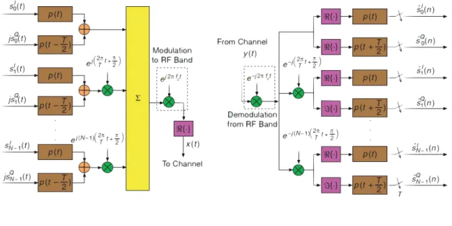
N data-carrying subcarriers, and then handled by a M-point inverseDFTto convert back to the TD. The obtained samples are parallel to serial (P/S)converted and a prefix or extension is added for transmission. In Fig. 2.4the transmission and reception blocks are shown. The simplest frequency mapping is to N contiguous subcarrier frequencies, with the remaining M - N being padded with zeros [10]. In this circumstance, the output samples are expressed as [10]
sn= 1
M
N−1
X
l=0 dl
N−1
X
p=0
ej2πp(n−Ml MN) =
N−1
X
l=0
g(n−lM
N)dl, n= 0,1, ..., M−1, (2.14)
where
gn=ej2π
(N−1)n M 1
M
sin(πN nM )
sin(πnM) (2.15)
andsn, n=−L,−L+ 1, ....−1, contains the CP. When SCMsignals are generated in this way, they are calledLocal Single Carrier FDMA (SC-FDMA)by theThe Third Generation Partnership Project-Long Term Evolution (3GPP-LTE)standards body [39] andDFT pre-codedOFDMby theWireless Initiative New Radio (WINNER)project [31]. DFT-OFDM has been proposed byWINNERas the uplink transmission format for wide area cellular scenarios, mainly due to its radio frequency impairment robustness properties [10] In [10] we can find an overview of variations of this procedure.
2 . 2 . ACC E S S S C H E M E S
Figure 2.4: SC-FDMA system block diagram [51]
2.2.2.2 Direct Equalization Methods
This section presents equalization structures whose parameters are designed directly from an estimate of the channel frequency response. We will focus on the structure of Decision Feedback Equalizer with a Hybrid Time-Frequency, since this equalizer will be of great importance for the thesis results.
Decision Feedback Equalizer With a Hybrid Time-Frequency Structure
This structure is calledhybrid DFE (HDFE), the feedforward filter operates in theFD on blocks of received signal, while the feedback operates in theTD[8], [15]. Instead of usingCP, data transmission with a PN extension (presented in the previous section, see (2.13)) must be considered to allowTDimplementation of the feedback filter [10]. Fig.2.5 showsHDFEstructure, where we can see the different stages of equalization. After the
DFTof the received signal,Rois obtained and then applied to the feedforward filter, with coeficientsCp, p= 0,1, ..., P−1 yielding the block signalZp, p= 0,1, ..., P−1 [10],
Zp=CpRp, p= 0,1, ..., P−1. (2.16)
After passing through the inverseDFT,Zp is transformed in to theTDto providezn. From the detected data sequence ˆdnand (2.13), the extended detected sequence ˆsnis given by [10]
ˆ
sn= ˆ
dn, n= 0,1, ..., M−1
pn−M, n=M, M+ 1, ..., P−1.
(2.17)
Ifbl, l = 1,2, ...., NFB, are the coefficients of the feedback filter, the signal at the input of the decision element is [10]
ˇ
C H A P T E R 2 . R E L AT E D WO R K
Figure 2.5: The HDFE structure [10]
and
yn= NFB
X
l=1
blsˆn−l (2.19)
is the feedback signal.
The computational complexity of theHDFEstructure is (P/M)log2(P)+NFB−(P/M) [10]. Let us now describe, starting from the channel frequency response, two design meth-ods for the receiver: zero forcing andminimum mean square error (MSE).
Zero Forcing:All interference must be canceled by the feedback filter [10]. If we define
Bp, p= 0,1, ..., P−1, the feedforward filter is given by [8]
Cp= 1
Hp
(1−Bp), (2.20)
Let AZF denote the NFB×NFB Toeplitz matrix, having as first row the firstNFB coef-ficients of the DFT of 1/|Hp|2, p = 0,1, ..., P −1 [10]. Let us also define the NFB-size column vectorvZF, having as elements the firstNFB coefficients of the inverseDFTof 1/|Hp|2, p = 0,1, ..., P−1 [10]. Then, the feedback filter that removes interference is the solution of the linear systemAZFb=vZF[8].
Minimum Mean Square Error:In this criterion, the coefficients of the feedforward and
feedback filters are chosen to minimize the sum of the power of the filtered noise, and the
2 . 2 . ACC E S S S C H E M E S
power of the residual interference [10]. TheMSEat the detection point is given by [10]
J=E[|dˇn−dn|2]. (2.21)
[10] shows that, by the Parseval’s equation, and by assuming that a) the past detected data symbols are correct ˆSp=Sp; b) both noise and data symbols are i.i.d. (independent and identically distributed) and statistically independent of each other; then J is given by
J= 1
p2
P−1
X
p=0
|CpHp−Bp−1|2σD2+|Cp|2σW2 , (2.22)
whereσ2
W is the variance of the data inFD.
In [8] the authors show that, setting the gradientJ with respect toCp, p= 0,1, ..., P−1, to zero, yields a relation between feedforward and feedback coefficients given by
Cp=
H∗
p(1−Bp)
|Hp|2+σ
2
W
σ2
D
, p= 0,1, ..., P−1. (2.23)
Let us define theNFB-size Toeplitz matrixAMMSE whose first row comprises the firstNFB coefficients of theDFTof 1
σ2
D|Hp|2+σW2 , p
= 0,1, ..., P−1 and the column vectorvMMSE whose
NFBelements are the firstNFBcoefficients of the IDFT of σ2 1
D|Hp|2+σW2, p= 0,1, ..., P−1 [10].
Substituting (2.23) into (2.22) and making the gradient of J equal to zero with respect to the feedback coefficientsb, it is seen thatbis the solution of the linear system ofNFB
equations andNFBunknownsAMMSEb=vMMSE. The complexity of theMSEmethod is similar to the zero forcing [10].
In [10] we can find an overview of others direct equalization methods, and a compari-son between them.
2.2.3 Filter Bank Multicarrier
In section2.2.1we described theOFDMsystems which has been the dominant technology for broadband multicarrier communications [17]. However, there are certain applications whereOFDMis not the best solution (e.g cognitive radios and uplink of multiuser mul-ticarrier system). In this section we will address an alternative toOFDM:FBMC, which some believe is a more effective solution [17]. FBMC, which has been studied even
be-fore the invention of OFDM, has been getting a lot of attention lately by a number of researchers. In this section this system will be described.
2.2.3.1 A unified formulation forOFDMandFBMC
There are some similarities betweenFBMC andOFDM. TheFBMC transceiver (block diagram depicted in Fig.2.6) can be also used in anOFDMsetting. The difference between
C H A P T E R 2 . R E L AT E D WO R K
filters are a rectangular pulse height one, withpT(t) having a duration ofT. The receiver prototype filterpR(t) has a lower width compared to the transmitter filter [17]. FBMC systems are designed for maximum bandwidth efficiency, but the durations ofpT(t) and pR(t) are greater than T, which causes, in FBMC, the overlapping of successive data symbols [17].
Figure 2.6: Block diagram of an FBMC transceiver [17]
The selection ofpT(t) andpR(t) depends on the adoptedFBMCmodulation technique. [17] describes two classes ofFBMCsystem. The first class is designed to transmit Quadra-ture Amplitude Modulation (QAM)data symbols (complex-valued) and the second class is designed to transmitPulse Amplitude Modulation (PAM)data symbols (real-valued). A short overview of these classes is presented next.
FBMCsystems forQAMsymbol transmission
As we showed on theOFDMsection, sucessive data symbols are isolated through the use ofCP. This characteristic ofOFDMsystem constitutes a loss of bandwidth efficiency.
This class of FBMC design allows orthogonality of diferent modulated data symbols without the use ofCP. This has the potential of achieving a higher bandwidth efficiency
thanOFDM[17].
When designing FBMCsystems, one of the goals is to design prototype filters that are robust under doubly dispersive channels. In [17] we can find the various designs procedures for this system.
FBMCsystems forPAMsymbol transmission
The symbol rate can be doubled and also the symbol spacing along the frequency axis can be halved in theFBMCsystem withPAMsymbol transmission (used when data symbols are real-valued), which means that the density of data symbols in the time-frequency phase-space latice can be quadrupled [17]. But it is worth noticing thatPAM transmission can achieve a data symbol density which is twice that ofQAMtransmission.
2 . 2 . ACC E S S S C H E M E S
Figure2.7presents astaggered multitone (SMT)5system structure that can be used for PAM symbol transmission. TheQAMsymbols (that are divided into its real-part and imaginary-part) may be thought of as the elements of a pair ofPAMsequences that are then transmitted with a time offset of half the duration of the symbol [17]. This is the
most efficientFBMCdesign [59].
In [17] we can find the design procedures for this system as for others alternatives.
Figure 2.7: Block diagram of an FBMC system using OQAM symbols: SMT [17]
2.2.3.2 FBMC’s advantages overOFDM
WhileOFDMis easier to implement and is more robust to timing offset [17],FBMChas
a number of advantages that makes it more suitable for future communication systems. We will now identify areas whereFBMCoutperformsOFDM:
• The uplink of anOFDMAnetwork, needs an almost perfect carrier synchronization of signals from different nodes. This is very hard to achieve in practice, particularly
in mobile networks. InFBMCsystems, the signal separation is achieved through filtering, avoiding the need for close to perfect carrier synchronization. Timing syn-chronization between different users is also avoided since the separation between
them is done through a filtering process [17].
• The filtering capability ofFBMCsystems makes them the perfect choice, in cogni-tive radios, for filling in the spectrum holes [17].
5this system has often been referred to asOFDM-offset QAM (OQAM), whereOQAMstands for offset
C H A P T E R 2 . R E L AT E D WO R K
• OFDMis sensitive to fast variations of the communication channels. On the con-trary, FBMC systems can be designed to be equally robust to channel time and frequency spreading [17].
• FBMC’s prototype-filters make this modulation a perfect match to applications where the channel is subject to a number of high-power interfering narrow-band signals [17].
2.2.4 Universal-Filtered Multi-Carrier
OQAMsystems (FBMC) introduced in previous section, ensure a much lower side-lobe level compared toOFDM. While this works well with single-cell, single user transmission, in the uplink case, additional interference paths appear between the interlacedOQAM symbol [59]. As we have seen earlier, future wireless communication systems will have to supportMTCandIoT, where these systems will have to support transmission of small data packet. A physical layer that is able to fulfill this target demands efficient support of
short transmission bursts.FBMC/OQAM, due to its long filter lenghts, is not an efficient
solution.
UFMCis a multicarrier transmission scheme proposed to overcome the problem ofICI inOFDMsystems. This technique is a generalization of filteredOFDM[17] ( where the filtering is done on a subcarrier level), i.e, an entire sub-band, that comprises multiples subcarriers, is filtered. One of the design criteria ofUFMCis to collect the advantages of filteredOFDMandFBMCwhile avoiding the respective disadvantages [63]. By using this technique, the effect of sidelobe interference on the immediate adjacent subchannels can
be significantly reduced [59]. Other advantage ofUFMCtechnique is the use of shorter filter lenghts6compared toOFDM CPlengths, which makes it suitable for short burst communication [59].
In [63] they provide simulations that show the superiority ofUFMCoverOFDMin a scenario where different traffic types are served by the network, both synchronous and
asynchronous. UFMCuses filters that are Dolph-Chebyshev-shaped ( with 40 dB side-lobe which comes on top of the sinc-shaped spectralside-side-lobe level attenuation) [63]. For delays greater thanCP,UFMChas a much better performance thanOFDM[63]. Moreover, it has a symmetric characteristic ofMSEvs delay, which allows better support of open-loop timing control mechanisms (desirable inMTCwhere we do not want to spend much energy in timing control) [63]. Devices signals arriving earlier than expected cause much less degradation inUFMCthan inOFDM.
UFMC(successfully demonstrated in [59] in an uplink scneario) can be considered as a potential candidate for future5Gwireless systems which will have to supportIoTand Massive Machine Communication (MMC).
6UFMCprovides higher spectral efficiency compared toOFDMdue to the absence ofCP[59]
2 . 2 . ACC E S S S C H E M E S
2.2.5 Generalized Frequency Division Multiplexing
Since the first generation of mobile communication systems, the requirements for new generations that have come include higher data rates [18], [63]. But for5Gtheres is a paradigm shift: the main scenarios are MTC [63], Tactile Internet [19], andWireless
Regional Area Network (WRAN) [54]. As we have seen earlier,OFDMused in4Gcan only
address the challenges presented by these scenarios in limited way.
A flexible multicarrier modulation scheme, namedGFDMhas been proposed for the air interface of5Gnetworks. The flexibility of this technique allows it to coverCP-OFDM and SC-FDEas special cases [38]. GFDM is based on the modulation of independent blocks, where each block consist of a number of subcarriers and subsymbols [38]. The subcarriers are filtered with a prototype filter that is circularly shifted in time and fre-quency domain [38]. This process reduces theOut-Of-Bound (OOB)emissions, making fragmented spectrum and dynamic spectrum allocation feasible without severe interfer-ence with incumbent services or other users [38].
GFDMis a promising solution for the5G PHYlayer because its flexibility can address the different requirements. SinceGFDMis confined in a block structure ofM Ksamples,
whereKsubcarriers carryM subsymbols each, it is possible to design the time-frequency structure to match the time constraints of low latency applications [38].
In a GFDM block, the overhead is kept small by adding a single CP for an entire block that contains multiple subsymbols. This benefit inGFDMcan be used to improve the spectral efficiency of the system or it can be traded for an additionalcyclic sufix
(CS), that allows to relax the synchronization requirements of multiple users in anMTC scenario [38], [63]. In Fig.2.8we can see a comparision between theCPused inGFDM and OFDM. All synchronization algorithms developed for OFDMcan be adapted for GFDM[38].
Figure 2.8: GFDM and OFDM frame Comparision for the MTC scenario [38]
2.2.5.1 System Description and Properties
C H A P T E R 2 . R E L AT E D WO R K
Figure 2.9: Block diagram of the transceiver [38]
Figure 2.10: Details of the GFDM modulator [38]
elements, which can be decomposed intoK subcarriers withM subsymbols each accord-ing tod~= (d~0
T
, ..., ~dMT−1)T andd~m= (d0~,m T
, ..., ~dKT−1,m)T. The total number of symbolsNis given byN=KM. The individual elementsdk,mcorrespond to the data transmitted on the
kth subcarrier and in themth subsymbol of the block. In Fig.2.10theGFDMmodulator details are shown. Eachdk,mis transmitted with the corresponding pulse shape [38]
gk,m[n] =g[(n−mK)mod N]e−j2π
k
Kn, (2.24)
withndenoting the sampling index. Eachgk,m[n] is a time and frequency shifted version of a prototype filterg[n]. The transmit samples~x= (x[n])T are obtained by superposition of all transmit symbols [38]
x[n] = K−1
X
k=0
M−1
X
m=0
gk,m[n]dk,m, n= 0, ..., N−1 (2.25)
From 2.25, a linear mapping of d~ containing KM data symbols to ~x containing N M
transmit samples according to [38]
~x=Ad,~ (2.26)
2 . 3 . M AC P R O TO CO L S F O R M TC COM M U N I CAT I O N S
whereAis aKM×KM transmitter matrix with a structure according to [38]
A= (g~0,0...gK~−1,0g~0,1...gK−1~,M−1). (2.27)
Lastly, on the transmitter side aCPofNcpsymbols is added to produce~xˇ. To take into account the effect of the wireless channel, the model
~y=H~x+w,~ (2.28)
is considered [38]. Therein~yis a vector containing the unequalized time samples at the receiver,w~ ∼ N(0, σ2) is a vector of white Gaussian noise samples with varianceσ2, and His a circular channel matrix that is built from an exponential power delay profile which denotes a Rayleigh multi-path channel. This allows employing zero-forcing channel equalization as is efficiently used inOFDM[38]. Introducing~z=H−1HAd~+H−1w~ as the
received signal after channel equalization, the linear demodulation of the signal can be expressed as [38]
~ˆ
d=B~z, (2.29)
whereBis aKM×KM receiver matrix. There are several receiver options for theGFDM demodulator:
• Thematched filter(MF) receiver whereBMF =AH , maximizes thesignal-to-noise ratio (SNR)per subcarrier, but with the effect of introducing self-interference when
a non-orthogonal transmit pulse is applied [38].
• Thezero forcing(ZF) receiverBZF =A−1completely removes any self-interference
at the cost of enhancing the noise [38].
• The linearminimum mean square error(MMSE) receiverBMMSE= (R2w+AHHHHA)−1AHHH makes a trade-offbetween self-interference and noise enhancement [38].R2wdenotes
the covariance matrix of the noise7.
Finally, the received symbolsd~ˆare demapped to produce a sequence of received values
~bˆc, which are then passed to a decoder to obtain~bˆ.
From this description of the transmitter and receiver, it can be concluded thatGFDM is a type of filtered multicarrier system [38].
In [38] they successfully implemented aGFDMtransceiver, proving that this system can be implemented with reasonable complexity using today’s technology.
2.3 MAC Protocols for MTC communications
Until now we gave an overview ofPHYlayer techniques that are alternatives toLTE-A’s OFDMand could possibly fulfill the requirements ofMTCin5G. But, in order to fully
7In the case of MMSE reception, the channel is jointly equalized in the receiving process, hence the
C H A P T E R 2 . R E L AT E D WO R K
exploit the applications given byM2Mcommunications, all layers in the network stack must provide adequate support in order to meet the service requirements. In this section we discuss existingMACprotocols that supportMTC.
MACprotocols for supportingMTCmust be designed with a set of requirements to satisfy the needs of the overlaying applications and scenarios [46]. We will now describe these requirements:
• Data Throughput -MACprotocols forMTCneed to be highly efficient and present
high throughput. Due to the limited channel/spectrum and the large number of devices accessing the channel, it is preferable that theMACprotocol minimizes the time wasted due to collisions or exchange of control messages [46]. The throughput has to be high in order to accommodate the very large number of devices [46].
• Scalability -MTCscenarios are expected to have a large number of nodes, and this number will only grow as the deployment of application scenarios withM2M com-munications becomes more prevalent [46]. Moreover, we have to take into account that the network conditions may be dynamic with nodes entering and leaving. Thus, it is imperative that theMACprotocol be easily scalable and adjusted gracefully to changing node densities with little or no control information exchange, and when new devices are added the fairness must be maintained [46].
• Energy Efficiency - This design requirement is one of the most important, in [46] three main factors are presented: 1) the fact that many of the devices in MTC networks are expected to be battery operated having then power constrains; 2) the economic impact of the power consumed by the communication structure; and 3) the environmental impact of the power consumed. Considering these factors, it is then very important that all operations associated withMTC be optimized to consume very low power [46]. Common methods to reduce MAC layer energy consumption include reducing the collisions, sleep scheduling, power control, and reducing idle listening [46].
• Latency - The network latency is a critical factor for many applications that rely on MTC. It is a factor that determines effectiveness and utility of the offered
ser-vices [46]. In certain applications (e.g. real-time control of vehicles) it is extremely important to make the communication reliable and fast [46]. Also, even if aMAC protocol is throughput efficient, it has to ensure that all devices get equal chance to
send their message [46]. It is worth noting that there are limitations to the amount of channel access latency that can be reduced, especially when the number of nodes increases [46].
• Coexistence -A significant fraction of the access networks forM2Mcommunications is expected to operate in the unlicensed bands, since the spectrum costs associ-ated with operating in licensed bands are reasonable [46]. With the increase of
![Figure 2.1: Block Diagram for multicarrier transmission [28]](https://thumb-eu.123doks.com/thumbv2/123dok_br/16567569.737863/32.892.224.661.283.612/figure-block-diagram-for-multicarrier-transmission.webp)
![Figure 2.3: OFDM frequency representation [13]](https://thumb-eu.123doks.com/thumbv2/123dok_br/16567569.737863/33.892.233.662.837.1071/figure-ofdm-frequency-representation.webp)
![Figure 2.4: SC-FDMA system block diagram [51]](https://thumb-eu.123doks.com/thumbv2/123dok_br/16567569.737863/39.892.148.800.161.388/figure-sc-fdma-system-block-diagram.webp)
![Figure 2.5: The HDFE structure [10]](https://thumb-eu.123doks.com/thumbv2/123dok_br/16567569.737863/40.892.222.661.154.590/figure-the-hdfe-structure.webp)
![Figure 2.8: GFDM and OFDM frame Comparision for the MTC scenario [38]](https://thumb-eu.123doks.com/thumbv2/123dok_br/16567569.737863/45.892.156.778.810.936/figure-gfdm-ofdm-frame-comparision-mtc-scenario.webp)
![Figure 2.11: Taxonomy of M2M MAC protocols [46]](https://thumb-eu.123doks.com/thumbv2/123dok_br/16567569.737863/49.892.223.666.416.698/figure-taxonomy-of-m-m-mac-protocols.webp)
![Figure 2.12: DPCF-M protocol frame structure [5]](https://thumb-eu.123doks.com/thumbv2/123dok_br/16567569.737863/52.892.148.808.173.502/figure-dpcf-m-protocol-frame-structure.webp)
![Figure 2.14: Code expanded random access [45]. (a) Current random access in LTE. (b) Code expanded random access](https://thumb-eu.123doks.com/thumbv2/123dok_br/16567569.737863/54.892.236.642.686.996/figure-expanded-random-access-current-random-access-expanded.webp)
![Figure 2.15: The 5G vision of a unified frame for diferent types of tra ffi c [63].](https://thumb-eu.123doks.com/thumbv2/123dok_br/16567569.737863/58.892.222.673.141.526/figure-vision-unified-frame-diferent-types-tra-ffi.webp)
