Ricardo Jorge Segurado Lampreia
Licenciado em Ciˆencias da Engenharia Electrot´ecnica e de Computadores
QoS in LEO Satellite Networks with
Multipacket Reception
Disserta¸c˜ao apresentada para obten¸c˜ao do Grau de Mestre em Engenharia Electrot´ecnica e de Computadores, pela Universidade Nova
de Lisboa, Faculdade de Ciˆencias e Tecnologia.
Orientadores : Lu´ıs Bernardo, Professor Auxiliar com Agrega¸c˜ao, FCT-UNL
Rui Dinis, Professor Auxiliar com Agrega¸c˜ao, FCT-UNL
J´uri:
Presidente: Prof. Doutor Pedro Amaral Arguentes: Prof. Doutora Teresa Vasques
Vogais: Prof. Doutor Lu´ıs Bernardo Prof. Doutor Rui Dinis
i
QoS in LEO Satellite Networks with Multipacket Reception
Copyright ➞ Ricardo Jorge Segurado Lampreia, Faculdade de Ciˆencias e Tecnologia, Universidade Nova de Lisboa
“The only source of knowledge is experience.”
Agradecimentos
Quero come¸car por agradecer ao meu orientador, o Professor Lu´ıs Bernardo, pela amizade, dedica¸c˜ao, disponibilidade e paciˆencia demonstrada ao durante todos os momentos desta disserta¸c˜ao. Foi sem d´uvida uma orienta¸c˜ao de excelˆencia. Agrade¸co ao coorientador Rui Dinis, pela disponibilidade prestada. E tamb´em queria deixar uma palavra de homenagem `
a mem´oria do coorientador, Professor M´ario Macedo, obrigado por tudo.
Agrade¸co aos meus colegas de laborat´orio Jos´e Vieira, Pedro Cunha, F´abio J´ulio, Bruno Branco, Miguel Duarte, Lu´ıs Irio, Jo˜ao Chala¸ca e Bruno Domingos pela amizade e pelo incr´ıvel espirito de camaradagem.
A todos os colegas que fizeram parte do meu percurso universit´ario, nomeadamente, Joana Martelo, Franscisco Esteves, Pedro Almeida, Pedro Vila¸ca, Andr´e Rocha, Gon¸calo Alves, Rui Borrego, Patrick Boura, R´uben Galante, Jo˜ao Filipe, Tiago Conraria, Ricardo Silva e Ricardo Ferreira, levo a vossa amizade por muitos e bons anos.
Quero agradecer aos meus amigos fora do curso, Emanuel Ferreira, Joaquim Conde, Pedro Ribeiro, Vera Rocha, S´onia Silva, Jos´e Martins, Liliana Teod´osio, Renata Cartaxo, Filipa Cristina e F´abio Oliveira pelo constante apoio.
Aos meus pais, Maria e Jos´e, pelo carinho, motiva¸c˜ao e apoio demonstrado ao longo da minha vida. Fizeram sempre o maior esfor¸co para que eu tivesse sucesso. E um obrigado ao resto da minha fam´ılia.
Um agradecimento especial aos projectos da FCT/MEC: MPSat - PTDC/EEA-TEL/099074/2008, OPPORTUNISTIC CR - PTDC/EEA-TEL/115981/2009, Femtocells - PTDC/EEA-TEL/120666/2010 e ADIN - PTDC/EEI-TEL/2990/2012, pelo apoio financeiro e tamb´em pelo equipamento
disponibilizado.
Resumo
As redes de sat´elite de baixa altitude (LEO), podem optimizar as redes sem fios terres-tres, para fornecer servi¸cos de banda larga aos terminais m´oveis (MT), numa escala glo-bal. Neste enquadramento, os sistemas de telecomunica¸c˜oes h´ıbridos com componente de sat´elite e LTE, como o LightSquared, prometem oferecer servi¸cos de alto d´ebito ub´ıquos.
Neste trabalho ´e realizada uma an´alise ao desempenho de um protocolo de acesso aleat´orio, que aplica Hybrid Network-assisted Diversity Multiple Access (H-NDMA) a uma rede de sat´elites LEO, sendo denominado de Satellite Random NDMA (SR-NDMA). Para al´em disto, o desempenho do sistema ´e avaliado considerando para a transmiss˜ao ascendente, uma arquitectura Single Carrier-Frequency Domain Equalization (SC-FDE) e tamb´em um receptor Multipacket Recepetion (MPR).
Na primeira parte deste trabalho ´e implementado um simulador SR-NDMA para medir o desempenho do sistema, com base em taxas de d´ebito, consumo de energia, atrasos e requisitos de qualidade de servi¸co (QoS). Para tal, s˜ao realizados v´arios testes com um gerador de tr´afego aleat´orio, baseado numa distribui¸c˜ao de Poisson, com o intuito de va-lidar o modelo anal´ıtico existente. Tamb´em s˜ao feitos testes com um m´odulo de gera¸c˜ao de tr´afego de tempo real, e ´e verificado se os requisitos de QoS s˜ao cumpridos.
Palavras Chave: QoS, Simulador SR-NDMA, Sat´elite LEO, SC-FDE, MPR, Acesso Aleat´orio
Abstract
Low Earth Orbit (LEO) satellite networks can improve terrestrial wireless networks to allow global broadband services for Mobile Terminals (MT), regardless of the users’ loca-tion. In this context, hybrid telecommunication systems combining satellites with Long Term Evolution (LTE) networks, like the LightSquared technology, are intended to pro-vide ubiquitous high-speed services.
This dissertation analyses the performance of a random access protocol that uses Hy-brid Network-assisted Diversity Multiple Access (H-NDMA), for a LEO satellite system network, named by Satellite Random NDMA (SR-NDMA). The protocol also considers a Single Carrier-Frequency Domain Equalization (SC-FDE) scheme for the uplink trans-mission and a Multipacket Reception (MPR) receiver. In this scenario, the transtrans-mission of data packets between MTs and the Base Station (BS) is made through random access and schedule access slots, organized into super-frames with the duration of a Round Trip Time (RTT).
A SR-NDMA simulator is implemented to measure the system performance in mat-ters of throughput, energy consumption, system delay and also the protocol capacity to meet Quality of Service (QoS) requirements. A set of simulations tests were made with a random Poisson process traffic generation to validate the analytical model. The capacity to fulfil the QoS requirements of a real-time traffic class was also tested.
Keywords: QoS, SR-NDMA Simualtor, LEO Satellite, SC-FDE, MPR, Random Access
Acronyms
3GPP Third Generation Partnership Project ARQ Automatic Repeat reQuest
BER Bit Error Rate
BS Base Station
CBR Constant Bit Rate
CDMA Code Division Multiple Access
CoS Classe of Service CPI Cyclic Prefix Insertion
DAMA Demand Assignment Multiple Access
DS-CDMA Direct Sequence Code Division Multiple Access EPUP Energy Per Useful Packet
FDE Frequency Domain Equalization
FEC Forward Error Correction
FDM Frequency Division Multiplexing FDMA Frequency Domain Multiple Access
FFT Fast Fourier Transform
GPD Generalized Pareto Distribution
GSM Global System for Mobile Communications
GSO Geostationary Orbit
HTTP HyperText Transfer Protocol H-NDMA Hybrid-ARQ NDMA
IB-DFE Iterative Block Decision-Feedback Equalizer IC Multi-stage Interference Cancellation
xiv ACRONYMS
ID User Identification
IEEE Institute of Electrical and Electronics Engineers IETF Internet Engineering Task Force
IFFT Inverse Fast Fourier Transform IPDV IP Packet Delay Variation IPER IP Packet Error Ratio IPLR IP Packet Loss Ratio IPTD IP packet Transfer Delay ISI InterSymbol Interference ISL InterSatellite Links
ITU-T International Telecommunication Union- Telecommunication LANs Local Area Networks
LDPC Low Density Parity Check LEO Low Earth Orbit
LTE Long Term Evolution MAC Medium Access Control MEO Medium Earth Orbit
MIME Multipurpose Internet Mail Extensions MIMO Multiple Input Multiple Output
MMSE Minimum Mean Square Error MPR Multipacket Reception
MT Mobile Terminal MUD Multi-User Detection
NDMA Network-assisted Diversity Multiple Access NGSO Non-Geostationary Orbit
NP Network Performance
OFDM Orthogonal Frequency Division Multiplexing OSI Open Systems Interconnection
xv
PIC Parallel Interference Cancellation PSK Phase Shift Keying
PSTN Public Switched Telephone Network QAM Quadrature Amplitude Modulation QoS Quality of Service
RA Random Access
RSSI Radio Signal Strength Indicator RSVP Resource Reservation Protocol RTP Real-time Transportation Protocol RTT Round Trip Time
R-ALOHA Reservation Aloha R-TDMA Request-TDMA SA Schedule Access
SC-FDE Single Carrier-Frequency Domain Equalization SIC Successively Interference Cancellation
SIP Session Initial Protocol SISO Single-Input Single-Output SLA Service Level Agreement SMS Short Message Service SNR Signal to Noise Ratio
SR-NDMA Satellite Random Network-assisted Diversity Multiple Access SYNC Synchronization Signal
S-NDMA Satellite-NDMA
TDMA Time Division Multiple Access UDP Used Datagram Protocol
UHF Ultra High Frequency
UMTS Universal Mobile Telecommunication System VAD Voice Activation Detection
xvi ACRONYMS
VoIP Voice over IP
WANs Wide Area Networks
Contents
Resumo ix
Abstract xi
Acronyms xiii
1 Introduction 1
1.1 Motivation . . . 1
1.2 Objectives and Contributions . . . 2
1.3 Dissertation Structure . . . 3
2 Related Work 5 2.1 Satellite Constellations . . . 5
2.1.1 LEO Satellite Systems . . . 6
2.1.2 Iridium Satellite System . . . 6
2.2 Multiple Access Schemes in Satellite Systems . . . 7
2.2.1 Code Division Multiple Access . . . 8
2.2.2 Frequency Domain Multiple Access . . . 8
2.2.2.1 Orthogonal Frequency Division Multiplexing . . . 9
2.2.2.2 Single Carrier - Frequency Domain Equalization . . . 10
2.2.3 Time Division Multiple Access . . . 10
2.3 Error Correction Schemes . . . 11
2.3.1 Forward Error Correction . . . 11
2.3.2 Diversity Techniques . . . 12
2.3.3 Automatic Repeat reQuest Schemes . . . 12
2.3.4 Hybrid-ARQ Error Control Schemes . . . 13
2.3.4.1 Type-I Hybrid-ARQ . . . 13
2.3.4.2 Type-II Hybrid-ARQ . . . 14
2.3.5 Multiple Input Multiple Output Scheme . . . 14
2.4 Medium Access Control Protocols in Satellite Communications . . . 15
2.4.1 Random Access Protocols . . . 15
2.4.2 Demand Assignment Protocols . . . 16
xviii CONTENTS
2.5 Physical Layer Solutions . . . 17
2.5.1 Multipacket Reception . . . 17
2.5.2 PHY-MAC Cross-Layer . . . 18
2.5.2.1 Network-assisted Diversity Multiple Access . . . 19
2.5.2.2 Hybrid-ARQ NDMA . . . 20
2.5.2.3 Satellite NDMA . . . 21
2.6 Quality of Service . . . 22
2.6.1 QoS Architectures for IP Networks . . . 23
2.6.2 Class of Service . . . 23
2.6.2.1 QoS Traffic Classes . . . 24
2.6.3 Real-Time Conversational Class . . . 25
2.6.3.1 Audio Traffic . . . 26
3 SR-NDMA Protocol Description and QoS 29 3.1 System Characterization . . . 29
3.1.1 Medium Access Control Protocol . . . 30
3.1.1.1 Random Access Mode . . . 30
3.1.1.2 Scheduled Access Mode . . . 31
3.1.2 Multipacket Reception Receiver Structure . . . 31
3.1.3 Analytical Average PER . . . 34
3.2 Traffic Generation . . . 35
3.2.1 Exponential Traffic Generation . . . 35
3.2.2 Audio Traffic Generation . . . 36
3.3 System Performance . . . 38
3.3.1 Throughput . . . 38
3.3.2 Packet Loss Ratio and Saturation Level . . . 39
3.3.3 Injected Load . . . 39
3.3.4 Energy Per Useful Packet . . . 39
3.3.5 Delay . . . 40
3.3.6 Jitter . . . 40
4 SR-NDMA Simulator 41 4.1 Simulator Implementation . . . 41
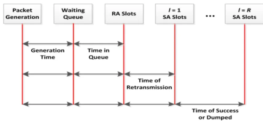
4.1.1 General Simulator Model . . . 41
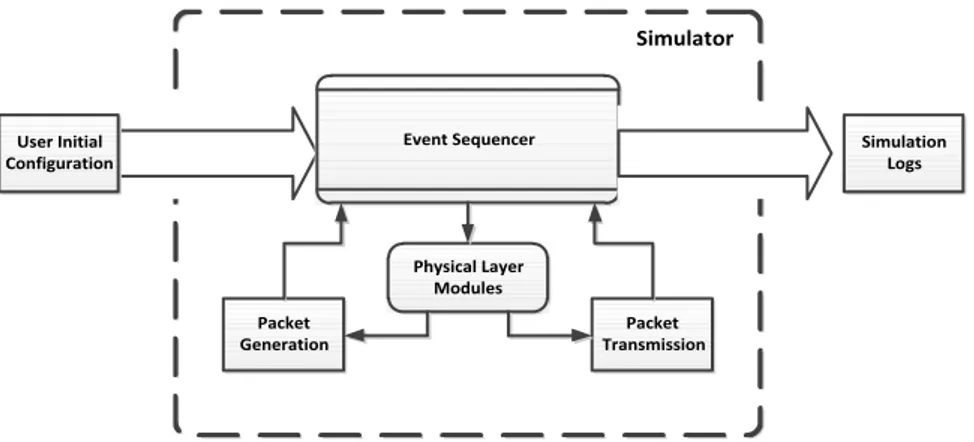
4.1.1.1 Simulator System Dynamics . . . 42
4.1.2 Initial Specifications . . . 44
4.1.3 Data Structures . . . 44
4.1.4 Random Traffic Generation . . . 46
4.1.5 Time Slots and Packet Copies Combination . . . 47
4.1.6 Packet Error Rate Calculation . . . 48
CONTENTS xix
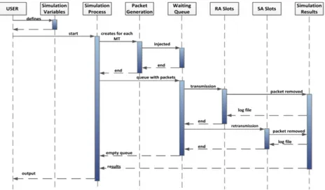
4.1.8 Packet Removal and Stored Information . . . 49
4.2 Real-Time Audio Modeling . . . 50
4.2.1 Audio Random Traffic Generation . . . 50
4.2.2 Codec Implementation . . . 51
4.2.3 Integration of Audio Modules . . . 51
5 Performance Analysis 53 5.1 Validation of the SR-NDMA Simulation Model . . . 53
5.1.1 Load and Saturation Level . . . 54
5.1.2 Throughput and Packet Loss Ratio . . . 55
5.1.3 Delay and Jitter . . . 56
5.1.4 System EPUP . . . 58
5.2 SR-NDMA with Audio Traffic Simulation Performance . . . 59
5.2.1 Statistical Analysis . . . 59
5.2.2 Throughput and energy efficiency . . . 60
5.2.3 Mean Delay and Jitter . . . 61
5.2.4 Simulation PER Comparison . . . 62
5.3 Overall Analysis . . . 63
6 Conclusions 65 6.1 Future Work . . . 65
Appendix 67
A H.323 69
B SIP 71
C Analytical nP⋆ and PER 73
List of Figures
2.1 OFDM signal processing [FABSE02]. . . 9 2.2 SC-FDE signal processing [FABSE02]. . . 10 2.3 Classification of techniques applied for MPR [LSW12]. . . 18 2.4 S-NDMA scheme signal [GaBD+12]. . . 22 3.1 RA packet transmission. . . 30 3.2 Receiver structure [PBD+13]. . . . 33
3.3 Real-time audio call model. . . 36 3.4 Possible time slots for delay. . . 40 4.1 Simulator block diagram. . . 42 4.2 Simulator use case diagram. . . 43 4.3 Simulator sequence diagram. . . 43 4.4 Interaction between data structures. . . 46 4.5 Packet generation sequence. . . 47 4.6 xi matrix forP=5 MTs. . . 48
4.7 Packet retransmission process. . . 49 4.8 VoIP packet generation process. . . 50 4.9 Codec ON/OFF matrix. . . 51 4.10 Final sequence diagram. . . 52 5.1 The MT total amount of load for a determined ρ. . . 54 5.2 Ls for: 5.2(a) 0 dB; 5.2(b) 12 dB. . . 55
5.3 System throughput for: 5.3(a) 0 dB; 5.3(b) 12 dB. . . 55 5.4 Packet loss rate for: 5.4(a) 0 dB; 5.4(b) 12 dB. . . 56 5.5 Mean transmission packet delay comparison for: 5.5(a) 0 dB; 5.5(b) 12 dB. 57 5.6 Jitter comparison for: 5.6(a) 0 dB; 5.6(b) 12 dB. . . 58 5.7 EPUP comparison for: 5.7(a) 0 dB; 5.7(b) 12 dB. . . 58 5.8 Success Rate for: 5.8(a) 500 RTT cycles; 5.8(b) 1000 RTT cycles. . . 60 5.9 EPUP results for: 5.9(a) 500 RTT cycles; 5.9(b) 1000 RTT cycles. . . 61 5.10 Average Delay results for: 5.10(a) 500 RTT cycles; 5.10(b) 1000 RTT cycles. 61 5.11 Jitter results for: 5.11(a) 500 RTT cycles; 5.11(b) 1000 RTT cycles. . . 62
xxii LIST OF FIGURES
List of Tables
2.1 ITU-T Classes of Service, examples of their application, and QoS parame-ters’ values. [SCJ11]. . . 24 2.2 Standard codecs. [SCJ11]. . . 28 3.1 Main statistics values assumed for the VoIP call generation [GL08][DSM04]. 38 C.1 Theoretical data results (a) [VGaB+13]. . . 73 C.2 Theoretical data results (b) [VGaB+13]. . . 74 C.3 Theoretical data results (c) [VGaB+13]. . . 75
C.4 Theoretical data results (d) [VGaB+13]. . . 76
List of Symbols
Bmax Maximum number of slots allocated by the satellite to a MT per RTT
Cpi,k Total number of packet copies
Eb Average bit energy associated to a given packet transmission
Fk,p Feed-forward coefficients of the linear receiver
Fξ,µ,σ GPD cumulative distribution function
Hk,p(r) Channel frequency response from the pth user, during therth transmission
J Number of members of a group of MTs associated with a satellite
Kl
k
One number of MTs that successfully transmit at retransmission k during an SR-NDMA epoch with l retransmission super-slots
Ls Saturation level
LT The total load injected into the system
l lth transmission in a epoch
N Maximum number of packets that a MT can send per epoch
N0 Power spectral density of the noise
Nk(r) The channel noise during the rth transmission
Ns Number of symbols in a data block
xxvi LIST OF SYMBOLS
n(P) Matrix containing all slots values, for all possible retransmissions, to be used
for all possible P MTs
n(P)⋆ Optimal matrix containing all slots values, for all possible retransmissions,
to be used for all possible P MTs
n0 Number of random access slots used in the initial transmission
nl Number of slots used for the l transmission
nR Number of random access slots used in the last transmission
P Number of transmitting users
Qx Gaussian error function
R Scheduled retransmissions
Sk,p Data block transmitted by a user p, in the frequency domain
Spi,k
Total amount of successful received packets in a specific RTT cycle by a given MT
sk,p Data block transmitted by a user p, in the time domain
T Round Trip Time in slots
TRT T Maximum interval of RTT simulation cycles
S Throughput
U Uniformly distributed variable
X Number of events which happen in a time unit
xi,k
The total amount of successful packets sent by a station in a specific RTT cycle
xi
Matrix representing the slots where the MTs transmitted until the current super-frame during the transmission epoch
Yk(r) Received signal, from multiple MTs, at the receiver in the frequency domain
xxvii
ǫ Packet loss ratio
λ Average packet generation rate per MT
λi,k Generated load in every RTT cycle
Ωl p
The space state defined by the SR-NDMA epoch withl retransmission super-slots and P MTs
ΨP,R Random state vector that defines the packet transmission behaviour
ψlP,l The random state vector with the number of MTs that successfully transmit
at retransmission
ρ Load factor
τmax Maximum delay value
σj Jitter
τT Sum of every successful packet delay in a givenTRT T interval
Chapter 1
Introduction
The Introduction chapter gives a first presentation of this work, with the motivation behind the dissertation subject, the main objectives and contributions, followed by the description of the work structure.
1.1
Motivation
Since the time that the satellite communications systems were primarily considered for naval and aeronautical purposes, to nowadays, that there was a continuous evolution which led to the integration of satellite systems in terrestrial telecommunications services. This integration can allow the telecommunication networks to provide wireless networks in a simpler, faster and more reliable way everywhere, at any time. As an example of this applicability, it is possible to guarantee the communication during natural disasters and emergencies when the terrestrial infrastructure is down.
With the constant urge to have better wireless broadband internet in Mobile Terminals (MTs) with guarantees of Quality of Service (QoS) and full connectivity, it is of interest to have the integration of terrestrial and satellite communication networks. In this context, hybrid telecommunication systems combining satellites with Long Term Evolution (LTE) networks, like the LightSquared technology, are envisioned to provide ubiquitous high-speed services.
The main obstacles in the integration of both networks, are related to the higher satellite propagation delays and the higher transmission requirements, inherent to the
2 CHAPTER 1. INTRODUCTION
distance of the satellite to the MT. On the other hand, the MTs must have low cost and be efficient in terms of energy consumption.
1.2
Objectives and Contributions
The objectives for this thesis are the development of a Satellite Random Network-assisted Diversity Multiple Access (SR-NDMA) protocol system [VGaB+13] simulator with multi-media traffic generator modules and the subsequent performance analysis.
Initially, a scenario composed by a Low Earth Orbit (LEO) satellite network is consid-ered, based on the Iridium satellite constellation, using Single Carrier-Frequency Domain Equalization (SC-FDE) scheme for the uplink transmission and Multipacket Reception (MPR). In this scenario, the transmission of data packets between MTs and the Base Station (BS) is made through random access and schedule access slots, organized in super-frames with the duration of a Round Trip Time (RTT).
A random exponential traffic generator (an approximation of the Poisson load gener-ator) is used to validate the SR-NDMA Medium Access Control (MAC) analytical model. The performance analysis is based on throughput, energy consumption, delay and jitter measurements.
In the second part of this thesis, the SR-NDMA simulator performance is used to evaluate if the QoS requirements of a real-time traffic class are satisfied. For this, an audio traffic class generator module is applied, composed by random time intervals of call arrivals/on hold and speech patterns. Also, it is created a module to generate the codec ON and OFF periods, to allow the packet injection into the waiting queue.
This work contributed to provide:
• a simulation testing environment for the SR-NDMA protocol with several config-urable parameters.
1.3. DISSERTATION STRUCTURE 3
1.3
Dissertation Structure
This dissertation is briefly described as follows: Chapter 2 refers the current state of the art with an overview on the satellite networks and the used multiple access schemes, error control mechanisms, MAC protocols, collision resolution methods and finalizing with a brief overview about QoS.
Chapter 3 presents the SR-NDMA protocol description, an explanation about the traffic generation considered for the simulator and the measurements of the system per-formance.
Chapter 2
Related Work
This chapter comprehends the state of the art study regarding: the satellite system con-sidered for this thesis, schemes for multiple access, several MAC protocols, the interaction between different types of layers and Quality of Service aspects.
2.1
Satellite Constellations
A satellite system can have two types of constellations: Geostationary Orbit (GSO) or Non-Geostationary Orbit (NGSO).
The geostationary terminology is applied when satellites present a circular motion around Earth, approximately, in twenty-four hours. This means that the motion is syn-chronized with the planet movement. With an altitude of 35786 km from the equator line, each GSO satellite can cover about one-third of the Earth’s surface, so the full coverage (not considering the Polar Regions) is achieved with a small constellation. The altitude of the satellite also has disadvantages for this kind of constellation, since it takes large antennas and a high transmit power to mitigate signal degradation. It is also necessary to consider the propagation delay of about 250 ms, which is not suitable for real-time traffic [HL01].
Regarding the NGSO satellite systems, they present a satellite asynchronous move-ment in relation to the Earth rotation, combined with two zones of distinct orbits: LEO which is located at an altitude between 500 to 2000 km from the Earth’s surface, and Medium Earth Orbit (MEO) from 8000 to 12000 km [BWZ00]. NGSO satellites have, in
6 CHAPTER 2. RELATED WORK
relation to the GSO, lower power requirements, and less propagation delay due to its alti-tude. Although the altitude makes it also necessary to have more satellites in the satellite network; some examples of current LEO satellite networks operating have 12, 24 and 66 (or more) satellites for global coverage (covering the polar regions contrarily to the GSO satellite networks) [Ipp08].
2.1.1 LEO Satellite Systems
LEO satellites can be used in certain sceneries which require low delay and low bit error characteristics [NBSL11]. Due to its low altitude, the LEO satellites must be served by a big number of earth stations to maintain transmission, that can be in some cases about 200 or more, and considering as well the risk of ”shadowing” of the signal by vegetation, terrain and buildings [Man95].
There are three types of systems that are differentiated in matters of main applications offered by the satellite. The first type is named Little LEO and is for low bit rate data applications, given by, for example, the ORBCOMM system [Maz99]. This system provides electronic mail and paging to mobile devices. The second system (Big LEO) is used for mobile telephony applications, like providing narrow-band mobile voice services. Iridium and Globalstar are examples of this kind of system. Finally, Broadband LEO offers high bit rate data, which provides primarily fixed, broadband connections comparable to urban wireline service [Uni02].
2.1.2 Iridium Satellite System
Motorola’s Iridium system was chosen to be the base of research for this thesis. It was con-ceived in 1987, based on a constellation proposed by Adams and Rider [AR87], intending to be the first private global wireless communication system to provide a wide diversity of services such as voice, data, fax and paging. In May 1998, the system was completely de-ployed as a constellations of 66 cross-linked (plus seven in-orbit spares), divided in groups of 11 satellites per plane, with a spacing of 32 degrees of latitude.
Inter-2.2. MULTIPLE ACCESS SCHEMES IN SATELLITE SYSTEMS 7
Satellite Links (ISL) to route traffic, while the regional gateways will handle call setup procedures and interface IRIDIUM with the existing public switched telephone network (PSTN). Iridium provides a network where the satellites communicate with other satellites that are near and in adjacent orbits. This kind of operation allows a simple call to roam over several satellites, coming back to the ground when downlinked at an Iridium gate-way, and patched into a PSTN for subsequent transmission to destination. Each satellite has on Earth’s surface 48 spot beams, with 402 Km of diameter apiece, to decrease the probability of existing dropped calls or missed connections.
Communication between satellites and handsets is done in the Iridium system using L-band spectrum, between 1616 and 1626.5 MHz. But other frequency bands can be con-sidered. Ultra High Frequency (UHF) and Very High Frequency (VHF) ranges (137 to 401 MHz) are commonly used by small LEO systems to provide low data rate transmis-sions, but none of them is appropriated for multimedia transmission. Higher data rates are available in the Ku (10 to 18 GHz), which are used to provide data communications to the subscriber, and Ka bands (18 to 31 GHz) to support communication between the satellite and the ground stations and between satellites [PRFT99].
The most important band frequencies, in relation to this thesis, which focuses the communication between the satellite and the user terminals, are the L band (1610 to 1626.5 MHz) and S band (2483.5 to 2500 MHz), which are generally used by LEO systems for telephone and Short Message Service (SMS) [BWZ00].
2.2
Multiple Access Schemes in Satellite Systems
8 CHAPTER 2. RELATED WORK
2.2.1 Code Division Multiple Access
CDMA allows each terminal to transmit continuously and together on the same frequency spectrum given by the satellite. To distinguish a terminal in a simultaneous transmission, each one has its own pseudo-random code word which is approximately orthogonal to everyone else. The receiver must know all code words in advance, in order to perform a time operation correlation to detect the specific code word of a desired terminal. The operation is made without any awareness of a terminal in relation to others [Rap01]. This is referred to the Direct Sequence CDMA (DS-CDMA) modulation, which is used in almost all 3G mobile cellular systems as their prime multiple access air-link architecture [AG11]. CDMA can offer several advantages by its approach of including every transmission in a unique signal. A set of CDMA networks can share the same frequency band, by the fact that the undetected signal behaves as Gaussian noise to all receivers without knowledge of the code sequence, giving them also protection and privacy. Because only a small portion of the signal energy is present in a given frequency band segment at any time, the CDMA can provide jamming resistance created by the presence of undesirable signals in the frequency band, and reducing the effects of multipath fading [Ipp08].
But the power of multiple terminals at a receiver can give performance issues to a CDMA network. The power determines the noise floor after decorrelation. If each terminal power is not controlled, the receiver will get different levels of power. This is known as the near-far problem. The near-far problem occurs when a stronger received signal imposes a higher noise level in the demodulaters for weaker signals, decreasing the probability of a successful transmission. In order to resolve the near-far problem, in each base station is implemented a power control operation. The satellite samples the radio signal strength indicator (RSSI) of each terminal linked to him, and then sends a power change command to the higher power terminals. This operation can only reduce or raise interferences caused by the terminals inside the same cell [Rap01].
2.2.2 Frequency Domain Multiple Access
2.2. MULTIPLE ACCESS SCHEMES IN SATELLITE SYSTEMS 9
channels. The allocation can be made on demand to terminals that have announced their intention to request a channel. When a terminal is transmitting or receiving (a channel has one frequency to uplink and another to downlink), the frequency band cannot be shared to another terminals. If a channel is not in use, then it turns to an idle state and it is impossible to be used by other terminals [Rap01].
Also the FDMA presents some limitations in large bandwidth scenarios, due to equal-ization complexity. FDMA was improved by two additional approaches: OFDM and SC-FDE.
2.2.2.1 Orthogonal Frequency Division Multiplexing
The OFDM technique is an evolution of Frequency Division Multiplexing (FDM), where several sub-carriers are transmitted in parallel and each one occupies a very narrow band-width. The transmission of the sub-carriers is modulated with Quadrature Amplitude Modulation (QAM) or Phase Shift Keying (PSK) at a lower transmission rate than the original signal. This allows a much more efficient struggle against multipath fading [PA02]. In figure 2.1, Inverse Fast Fourier Transform (IFFT) is applied on blocks of M data symbols at the transmitter side to generate the multiple sub-carriers. After this, it is inserted a cyclic prefix (CPI) to carry the repetition of the last symbol, in order to avoid InterSymbol Interference (ISI) with the previous block and make the received block look periodic, simulating a circular convolution and allowing an efficient FFT operation.
Figure 2.1: OFDM signal processing [FABSE02].
enve-10 CHAPTER 2. RELATED WORK
lope peaks that should be reproduced. But this solution also as a disadvantage, because the increased power back-off will raise the cost of the power amplifier and also the power consumption [FABSE02].
OFDM is used, for example, in the Institute of Electrical and Electronics Engineers (IEEE) 802.11 and 802.16 standards, and in the LTE and LTE Advanced [BS04].
2.2.2.2 Single Carrier - Frequency Domain Equalization
SC-FDE is an alternative to OFDM, where it is applied frequency domain equalization to a single carrier. This technique has some of the OFDM advantages as well, such as performance, efficiency and low signal processing complexity. The usage of a single carrier in SC-FDE decreases the PAPR. Therefore, the power amplifier of an SC transmitter does not need a big linear range to support a given average power, which represents a lower complexity of the power amplifiers. Also results in more efficient power consumption due to the reduced power back-off.
In figure 2.2, it is possible to see that the main difference of OFDM and SC-FDE is the placement of the IFFT block from the transmitter to the receiver side. This allows the conversion of Frequency Domain Equalization (FDE) signals into time domain symbols [FABSE02].
Figure 2.2: SC-FDE signal processing [FABSE02].
It is possible the coexistence of both systems, like for instances, in 3GPP LTE, SC-FDE is used in the uplink, and OFDM used in the downlink, avoiding IFFT operation complexity on the transmitter side, improving the terminal battery resources [BS04].
2.2.3 Time Division Multiple Access
2.3. ERROR CORRECTION SCHEMES 11
terminal, since they can listen for other base stations during idle time slots [Ipp08]. However, the TDMA requires a high synchronization overhead to guarantee synchro-nization between terminals and the correspondent data bursts. Also, it is usually necessary to have adaptive equalization to mitigate the effects of multipath propagation caused by very high transmission rates.
The TDMA was used in the Second Generation cellular systems like the Global System for Mobile Communications (GSM), but continues to be used mixed with other approaches (e.g. TDD OFDMA).
2.3
Error Correction Schemes
In a wireless communication channel transmission errors may occur due to several factors, like for instance, multipath fading. In order to detect and correct these errors, techniques such as Forward Error Correction (FEC) and Diversity Techniques are used.
2.3.1 Forward Error Correction
FEC techniques include redundant information inside each data block sent, which allows the receiver to know if the data block is successfully received, and in case of failure, what was the error. This technique differs from error-detecting codes, since they include only the necessary redundant information for the receiver to know that an error exists, but without knowing what the error is [AS02].
12 CHAPTER 2. RELATED WORK
2.3.2 Diversity Techniques
To improve the performance in deep fade channels, it is necessary to ensure that the message signal passes through multiple signal paths. The combination of multiple versions of the original signal makes a new improved signal capable of mitigating the fading effects and channel interferences.
There are several ways to obtain diversity: over time, over frequency and over spatial domain. In time diversity, when a MT sends a data symbol with errors, the BS requests more retransmissions in different periods of time. Examples of this approach are the Automatic Repeat reQuest (ARQ) and Hybrid-ARQ schemes.
Frequency diversity uses several frequency channels to transmit the replicas of a data symbol. Since it tries to transmit data symbols more frequently, issues like ISI can appear. The frequency diversity deals with this problem in three different ways: Single-carrier systems with equalization, direct-sequence spread spectrum and OFDM.
In space diversity, the transmission signal is sent through different propagations paths. The Multiple Input Multiple Output (MIMO) technique uses multiple antennas in the transmitter and in the receiver to improve the performance of a wireless transmission [TV09].
2.3.3 Automatic Repeat reQuest Schemes
ARQ protocols are reliable data transfer protocols that are based in retransmissions. The receiver passes the information to the sender of what has been received with and without errors in order for the sender to retransmit what was not received correctly. The exchange of information between the receiver and the sender is performed by control messages [LCM84].
2.3. ERROR CORRECTION SCHEMES 13
2.3.4 Hybrid-ARQ Error Control Schemes
Hybrid-ARQ is a scheme where the FEC subsystem is combined into an ARQ system. When this combination is done in a proper way, the disadvantages of both schemes can be overcome. The FEC scheme allows the correction of frequent error patterns, decreasing the number of retransmissions and increasing the system throughput. Also, the combination of FEC and ARQ schemes gives the advantage when an uncommon error pattern is detected. In this case, the receiver requests a retransmission rather than passing the erroneous decoded code word to the end user [LCM84].
In resume, the Hybrid-ARQ has higher reliability and throughput than separate FEC and ARQ schemes respectively. With all these advantages, Hybrid-ARQ was chosen to be used in 3GPP LTE program [SBT11].
The Hybrid-ARQ schemes can be divided in two categories: Type-I Hybrid-ARQ and Type-II Hybrid-ARQ [LCM84], and will be approached on the following sub-sections.
2.3.4.1 Type-I Hybrid-ARQ
In type-I Hybrid-ARQ, a FEC coder is used at the sender and a FEC decoder is used at the receiver to detect errors in transmissions. The message and the error detecting parity bit are encoded using a FEC code in the sender. In the receiver side, the error correction parity bits are used to correct channel errors. The result of the FEC decoder is an estimation of the original message, plus the error detection parity bits, which is tested by the error detection decoder to determine if the message should be accepted or rejected. This protocol can increase the system efficiency in certain scenarios, like for instance, when the message is long or when the channel signal strength is low. By adding extra FEC parity bits, the unsuccessful transmissions probability decreases. It is possible to have a coding gain if a compensation between the reduction of transmissions and the increase of message length is made.
14 CHAPTER 2. RELATED WORK
2.3.4.2 Type-II Hybrid-ARQ
Type-II Hybrid-ARQ was planned to operate with the efficiency of plain ARQ in good quality signal and obtain the improvement of type-I Hybrid-ARQ in poor quality signal.
In this protocol, the message is encoded and sent with error detection bits. The FEC parity bits are now sent in separate transmissions. When the first transmission is received error free, there is no need to send the FEC parity bits [CC84]. If in the first transmission the receiver detects an error, it saves the message and requests a retransmission. The sender retransmits the FEC error detection parity bits, which are then used by the receiver to correct the errors in the stored message.
So, the type-II Hybrid-ARQ protocol allows the system to adapt to changing channel conditions by implementing incremental redundancy [Wic95].
2.3.5 Multiple Input Multiple Output Scheme
Since the MIMO technique has become a standard for WiMax and 3GPP LTE [SBT11], it is important to give a brief description about the approach.
In MIMO scheme, the total transmission power can be divided among multiple spatial paths. This puts the capacity of the MIMO system closer to the linear regime to each spatial path, and therefore, increase the aggregated spectral efficiency.
To implement a MIMO communication system space-time codes are used with multiple transmitters to provide spatial as well as temporal redundancy in the data received by an array of antennas. Space-time codes can be used in two different ways: coding adjustments and fixed codes.
In the first way, the receiver informs the transmitter about the propagation channel information, so the transmitter can adjust its coding. This brings advantages in terms of capacity, but it can be difficult to apply in dynamic environments.
On the other way, fixed codes of various rates are used to share transmitted power equally among all spatial channels, offering good performance over all channels.
2.4. MEDIUM ACCESS CONTROL PROTOCOLS IN SATELLITE COMMUNICATIONS15
2.4
Medium Access Control Protocols in Satellite
Commu-nications
A Medium Access Control (MAC) protocol defines rules for stations to access to the shared medium and for the communication with each other in an orderly and efficient manner [GL00]. Not all MAC protocols are suitable for satellite communications, due to the specific requirements, for instance, handling high propagation delay. A large range of protocols that are applied in Local Area Networks (LANs) and Wide Area Networks (WANs) cannot be used for this purpose [Pey99].
MAC protocols can be classified as distributed or centralized. The distributed MAC protocols are capable of listening the physical medium to detect any ongoing transmis-sions, also known as carrier sensing, and minimize the probability of occurring a collision using collision avoidance algorithms.
The centralized MAC protocols move all the arbitration and complexity to the BS. So, the BS decides which and when a MT can access the medium. This allows a higher throughputs and energy efficiency.
The centralized category is divided into Guaranteed, Hybrid and Random Access. The Hybrid access also is divided in Random Reservation Access and Demand Assign-ment [GL00]. In this thesis, it is important to give a more detailed explanation about the Random Access and Demand Assignment protocols, since they are used for the transmis-sion and retransmistransmis-sion process, respectively.
2.4.1 Random Access Protocols
With Random Access protocols, each MT makes its own decision regarding when to access the channel. Since the protocols are contention-oriented and very susceptible to collision occurrences, there is no guarantee of a successful transmission.
ap-16 CHAPTER 2. RELATED WORK
plications or guarantee QoS [Pey99].
A list of protocols that use random access is presented in [Pey99]: Pure Aloha, Slotted Aloha and Selective-Reject Aloha.
In Pure Aloha, the ready stations transmit their packets in a non-synchronous way. When one or several packets collide, each station is aware of this occurrence and retrans-mits the packet after a random delay. This random delay has the purpose of providing stability to the protocol. Due to a high probability of packet collision, the Pure Aloha protocol presents a maximum throughput of 18%.
Slotted Aloha improves the original Aloha protocol, by imposing the synchronization of every packet transmission in a defined length of time slots. Thus, the number of packet collisions is reduced and the throughput can achieve up to a maximum of 37%.
In Pure Aloha, although the collision between packets is partial, the packet is totally destroyed. The Selective-Reject Aloha avoids the total destruction of the packet, by di-viding the packet into sub-packets and giving to each one, their own header. Therefore, when a new collision occurs, only the sub-packets involved are retransmitted. In terms of efficiency, the Selective-Reject Aloha is better than the original Pure Aloha, but the insertion of the sub-packet headers limits the throughput to a maximum of 30% [Pey99].
2.4.2 Demand Assignment Protocols
Demand Assignment Multiple Access (DAMA) techniques permit a set of MTs to effi-ciently share satellite resources on a demand basis, using a FDMA or TDMA architectures to allocate capacity [Fel96]. A MT that receives a slot allocation in a particular frame may use it to send one or more frames. Depending on the fraction of capacity used for the signaling information, the efficiency may be above of 70%. The reservation on demand can be implicit or explicit [Pey99].
2.5. PHYSICAL LAYER SOLUTIONS 17
from successfully capturing all the slots in a frame for an indefinite time period [Ret80]. In explicit reservation, a single reservation slot is assigned to each MT in every frame. The reservation is made by a control subframe that consists of a sequence of bits and comes in each frame. This is also used to announce upcoming transmissions [Pey99].
Request-TDMA (R-TDMA)[CD01] is a good example of explicit reservation. The scheme uses a fixed-assignment technique for making reservations and allows the total, available channel capacity to be shared among all stations that are busy [Ret80].
2.5
Physical Layer Solutions
MAC protocols are traditionally used to solve collisions; however, they cannot handle all the possible cases. In [HKL97][ZR94] was observed that signal capture mechanisms can decode a packet that has a higher power, in comparison with all the other packets involved in a certain collision. This can be made by the Physical layer.
In the Physical layer, data is converted into symbols for transmission, and performed the reverse process for the reception. Also, it gathers the received data into frames which are passed to upper layers [BNNK08].
A Physical layer solution, to issues involving packet collisions is called MPR.
2.5.1 Multipacket Reception
MPR is defined as the ability of receiving and decoding more than one packet involved in collisions from concurrent transmitters [LSW12]. This characteristic allows a less re-strained transmission of the packets in relation to the conventional MAC protocols, where only one packet is received at a given time [BCA12].
According to [LSW12], the MPR techniques in a wireless random network can be classified based on the Transmitter perspective, Trans-Receiver perspective and Receiver perspective, as shown in figure 2.3.
The Receiver perspective, in particular the Multi-User Detection (MUD), is the most relevant to the subject of this thesis, since it is present in the implemented receiver.
18 CHAPTER 2. RELATED WORK
extremely complex to implement and computationally exhaustive [And05]. Therefore, the complexity associated with these techniques led to the investigation of low-complexity solutions as sub-optimal linear multi-user receivers [LV89].
MPR(System Transmitter( Perspective Trans-receiver( Perspective Receiver( Perspective
CDMA OFDMA Multi-antenna(
MIMO Signal( Separation Polynomial( Phase(Sequence Resource(allocation( BNetwork(assisted U
TVTP CMA MMA KMA AKMA
Bit-map-assisted Multiple( Retransmission Matching(Filter Multi-User( Detection Sub-optimal Optimal(BMLSEU Linear Nonlinear
Decorrelater MMSE Successive(IC(
BSICU Parallel(IC( BPICU
Figure 2.3: Classification of techniques applied for MPR [LSW12].
Sub-optimal MUD techniques are divided into linear and non-linear. The most known linear MUD techniques are the Decorrelated detectors and the Minimum Mean Square Er-ror (MMSE) [LV90][XSR90]. They have the advantage of producing an optimal value for the near-far resistance performance metric. However, the high complexity is a disadvan-tage in comparison with the non-linear MUD techniques.
Non-linear MUD techniques use interference estimators and remove the interference from the received signal before the detection [LSW12]. The most known non-linear MUD is the Multi-stage Interference Cancellation (IC), which is divided in Successively Interfer-ence Cancellation (SIC) [WGLA09] and in Parallel InterferInterfer-ence Cancellation (PIC) ways [BCW96]. Non-linear MUDs have a low complexity, but in terms of performance, the non-linear are worse than the linear MUDs.
2.5.2 PHY-MAC Cross-Layer
2.5. PHYSICAL LAYER SOLUTIONS 19
on higher layers in terms of wireless communications, despite the OSI reference model specifies that layers do not share information between them except through the interface. This interaction gives advantages, since all layers are affected by wireless link charac-teristics, thus, the union among protocols at different layers allows adaptability to changing channel conditions [BNNK08].
There are several research works covering the design of to the cross-layer between the Physical and the MAC layers. In 2007, [GLASW07] published as study of a cross-layer MAC algorithm for Wireless Local Area Network (WLANs) considering an error free transmission, using single antenna terminals and multiple antenna access points. A year later, [HLZ08] unites the MPR protocol with MAC and proposes an adaptive resource al-location algorithm for MIMO WLAN. More recently, in [RP12] is studied a cross-layered PHY-MAC algorithm with MIMO and over a jittery channel, revealing a high Signal to Noise Ratio (SNR) and a low bit error rate.
Network-assisted Diversity Multiple Access (NDMA) research work is approached in the next sub-section, which is the base of this thesis project.
2.5.2.1 Network-assisted Diversity Multiple Access
NDMA [TZB00] is an approach to the collision resolution problem to recover packets from multiple collisions. Diversity combining and signal separation techniques are used in order to recover and retransmit the collided packets. In the NDMA scheme, in case of a collision between P users occur in a given time slot, the same P users repeat their transmission for a total of P times, so that P copies of the collided packets are received. The signal received from the collision is stored in memory, so that it can be combined with future retransmissions, allowing the extraction of collided packets information.
The protocol has the advantage of not imposing penalties to the throughput efficiency for multiplexing variable-bit-rate data sources, since the number of collided users is equal to the number of required slots.
20 CHAPTER 2. RELATED WORK
for a frequency selective channel environment using multiuser receivers and CDMA sys-tems. User Identification (ID) signature sequences were considered, with the purpose of making easier the collision detection and resolution process when multipath effects are present. Despite of achieving a good throughput performance with this technique, ID se-quences also give disadvantages because they grow linearly instead of logarithmically with the number of users, introducing a considerable overhead process. Zhang et al [ZST99] present a method to resolve packet collision problem without the need of an orthogonal ID sequence. The method is called blind signal separation and is less computationally de-manding in relation to the initial NDMA scheme, due to its proportionality to the number of colliding packets.
To improve the multiuser detection in NDMA protocols, it was presented a new re-source allocation mechanism. This mechanism, developed in [SRGM07], adjusts the prob-ability of false alarm of each user controlling the average number of active time-slots per user, which allows the regulation of the typical delay degradation of a fixed resource allo-cation scheme, ensuring different levels of QoS.
Madueno and Vidal [MV05] studied the usage of the NDMA protocol for broadcasting in ad-hoc networking with and without combining retransmissions. A new protocol was defined which does not require feedback from the receiver part.
2.5.2.2 Hybrid-ARQ NDMA
Hybrid-ARQ NDMA (H-NDMA) is the combination of an H-ARQ technique with NDMA, proposed in [GaPB+11]. The H-NDMA access mechanism forces the MTs to transmit a quantity of packet copies greater than the number of collided MTs. The BS defines the time slots, which are used by MTs to send data frames. Several MTs could use a given channel, and the maximum number J that is doing it, is controlled by the BS. The BS has also the duty of detecting collisions and to inform the MTs that they occur through a broadcast downlink channel. After the involved MTs receive the collision information signal, they resend their packets.
synchro-2.5. PHYSICAL LAYER SOLUTIONS 21
nization signal (SYNC) to alert the MTs with new packets to transmit. Each epoch is defined by the numberP of MTs that transmit data, and it was assumed that this number fits 1 ≤P ≤ J. When a collision occurs between P MTs, the base station requests P-1 retransmissions. Additional retransmissions are made if the error persists. Before each additional retransmission, an acknowledgment signal is sent by the BS to MTs, defining the ones that must retransmit at the next slot. The epoch ends when all packets are successfully received, or when the number of retransmissions is equal to the maximum allowed.
The H-NDMA presents advantages in terms of network capacity and packet delay, when compared with the classic NDMA and Hybrid-ARQ protocols. Incresead scalability was another characteristic shown by this new protocol.
2.5.2.3 Satellite NDMA
H-NDMA was proposed to enhance NDMA’s error resilience capability, but is unsuitable for satellite networks due to the multiple control packets required to control additional retransmissions and acknowledgments. These introduce a delay and jitter incompatible with several kinds of QoS requirements [GaBD+12].
The Satellite-NDMA (S-NDMA) protocol, proposed in [GaBD+12], is very similar to the H-NDMA protocol by the fact that it also uses a combination of H-ARQ and NDMA protocols. The packet transmission process of the S-NDMA scheme can be seen in figure 2.4.
Individual packets are firstly scheduled to P+n0 slots in an initial super-frame for P
transmitting MTs, where n0 ≥ 0 defines a number of redundant retransmissions used to
improve error resilience. In case of unsuccessful transmission, additional groups of slots may be scheduled in future super-frames, reducing the number of round trip times required to achieve a successful reception.
22 CHAPTER 2. RELATED WORK
Figure 2.4: S-NDMA scheme signal [GaBD+12].
2.6
Quality of Service
When a connection is accepted into a network, certain conditions such as delay, delay variation (jitter), packet error rate (PER) or throughput, may be guaranteed by the system [AUB99]. This is called QoS, but the concrete definition is not entirely clear, since it does not exist a standard nomenclature.
In 2001, a general model for QoS is proposed in [Har01] with three levels: intrinsic, perceived and assessed [Har01].
Intrinsic QoS level considers all service features related to the Network Performance (NP), like network efficiency or resources. This guarantees the functions needed to the communication and is the key for quality perceived and accessed by the end-users.
The perceived QoS level is based in the experience of the customer on a specific service. It is influenced by the customer’s requirements and opinions, as also what is offered and achieved by who is providing the service. Since customer expectations cannot be translated into a technical language, it is necessary to define in advance a Service Level Agreement (SLA), some parameters of quality and assessment criteria desired by the customer and corresponding to the ambitions of the service providers.
2.6. QUALITY OF SERVICE 23
facts of this decision are based in the perceived quality of the service, the associated costs and also the capacity of the service provider to resolve the customer complaints [SCJ11].
2.6.1 QoS Architectures for IP Networks
A main principle for the QoS architectures is to sustain end-to-end service models across a wide diversity of internet platforms. As an example of this architectures, the Internet Engineering Task Force (IETF) has conceived two architectures specifically to support guaranteed QoS for streaming multimedia.
First it created the Integrated Services architecture, where the main characteristic is to reserve bandwidth in advance to groups of users, supporting a multicast environment. It used the Resource Reservation Protocol (RSVP) based on a spanning trees supported by data structures in the router’s memories, to route traffic for multiple senders to mul-tiple receivers, also allowing singular receivers to transit between channels to eliminate congestion.
But there are some important downsides in the integrated service architecture like the reservation of resources to a large scale scenario and the vulnerability of the network to a possible loss of the per-flow state, that is internally stored in the routers. So IETF created another architecture called Differentiated Services based on the classification of the traffic. The treatment given to the packets is determined by the traffic class and the per hop behavior established. A packet can have a different requirement of delay or jitter associated to a specific service, like for instance, regular or premium, and so it can have a priority in the forwarding to another router [TW10].
2.6.2 Class of Service
The class of Service (CoS), also known as QoS class, relates the parameters of quality of service with types of traffic, network features and service applications. There are basically two main levels to describe the CoS: application and network.
24 CHAPTER 2. RELATED WORK
non-interactive (like file download and sending e-mail) and interactive (web browsing and grid computing). The separation between non-elastic and elastic classification is based on the amount (fixed or dynamic) of bandwidth required by the application.
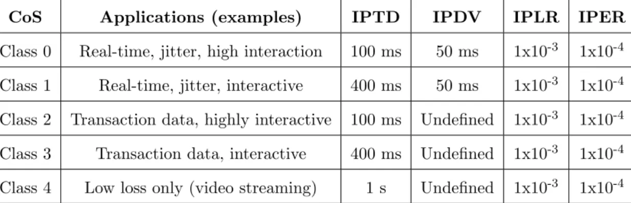
At the network level, there are several definitions for the most important classes, based on a set of applications and QoS parameters. It will be shortly described the definitions proposed by four organizations. The International Telecommunication Union-Telecommunication (ITU-T) proposed five service classes with different applications and a set of values for IP Packet Delay Variation (IPDV), IP Packet Error Ratio (IPER), IP Packet Loss Ratio (IPLR), and finally, IP packet Transfer Delay (IPTD), which are presented in table 2.1. These values are constraints for the traffic transported between the user network interfaces [SCJ11].
CoS Applications (examples) IPTD IPDV IPLR IPER
Class 0 Real-time, jitter, high interaction 100 ms 50 ms 1x10⁻³ 1x10⁻⁴ Class 1 Real-time, jitter, interactive 400 ms 50 ms 1x10⁻³ 1x10⁻⁴
Class 2 Transaction data, highly interactive 100 ms Undefined 1x10⁻³ 1x10⁻⁴ Class 3 Transaction data, interactive 400 ms Undefined 1x10⁻³ 1x10⁻⁴
Class 4 Low loss only (video streaming) 1 s Undefined 1x10⁻³ 1x10⁻⁴
Table 2.1: ITU-T Classes of Service, examples of their application, and QoS parameters’ values. [SCJ11].
2.6.2.1 QoS Traffic Classes
2.6. QUALITY OF SERVICE 25
not guaranteed, but presents a low bit error rate. Web browsing and telnet applications are supported by this class. The Background class has the same characteristics of the Interactive, but does not request a response pattern for the destination at a given time, like for example, the email application.
Finally, IEEE has defined eight traffic types for the LAN networks in the 802.1d stan-dard and four access categories in the wireless networks in the 802.11e stanstan-dard. For the LAN network, each traffic type is differentiated by the user priorities. It only supports QoS requirements on the voice and video traffic, such as jitter and delay, supported by a priority mechanism. The services in the wireless network are classified as background, best effort, video and voice [SCJ11].
In the context of this thesis, it will be considered the Conversational class as defined by 3GPP , and the respective QoS constraints.
2.6.3 Real-Time Conversational Class
The Conversational class is designed to handle bi-directional real-time traffic between groups of human end-users. Examples that use real-time Conversational class are the voice over IP (VoIP) and video conferencing tools.
This class has the most demanding delay requirements in relation to the other three QoS classes. The Conversational class presents the strongest and most stringent QoS requirements.
For voice applications, the audio transfer delay requirements are directly linked to the interactivity of the end users. One-way end-to-end delay is advised to be limited to 150 ms and in the radio link the maximum delay should be less than 20 ms. Also it must be considered that the human ear is highly intolerant to short-term delay variation (jitter), and so it should be as low as 1 ms.
26 CHAPTER 2. RELATED WORK
packet loss, depending on the video coder that is applied and the level of error protection used [AMCV06].
2.6.3.1 Audio Traffic
VoIP, IP-telephony or broadband telephony are terms that describe the same thing, namely transmission of the human voice over a data network, using the Internet Protocol.
As oppose to the ordinary PSTN, where every call has a dedicated connection between callers, in the VoIP calls the capacity is shared with themselves and with other kind of data as well [GL08].
VoIP presents several benefits such as, reduced communication cost, the usage of the integrated IP infrastructure and the participation in a multimedia application. Also, the advantages of packet-switched networks apply, like for instance, high network utilization while keeping the quality of circuit-switched networks. To minimize bandwidth consump-tion, VoIP carries voice data using speech data compression and/or header compression [DSM04].
The VoIP communication is basically made by three parts: data streams, call control and codecs.
Data Streams
VoIP usually sends data streams through Real-time Transportation Protocol/Used Data-gram Protocol (RTP/UDP). RTP is an Internet standard protocol created to transport real-time data such as audio and video over an Internet. It consists in a data part which supports timing reconstruction, security, loss detection and content identification for real-time applications, and a control part that gives QoS feedback, identification and synchro-nization between different types of media streams [GL08].
2.6. QUALITY OF SERVICE 27
Call Control
Call control is made by a separate protocol such as H.323 standard by ITU-T, Session Initial Protocol (SIP) or Voice Activation Detection (VAD). VAD is used to monitor the RTP streams in a conversation while H.323 and SIP handle the initiation and termination of the session. A briefly explanation about the H.323 and SIP protocols is given in the annex A and in the annex B, respectively.
The VAD primary function is to provide an indication of speech presence in order to facilitate speech processing as well as possibly provide delimiters for the beginning and end of a speech segment. It is an important enabling technology for a variety of speech-based applications including speech recognition, speech encoding, and hands-free telephony [LB05]. The VAD algorithm begins by extracting some measured quantities from the input signal and compares it with thresholds values, given by the characteristics from the noise and speech signals. The values that exceed the thresholds are considered as voice-active [TO00].
VAD is able to increase the number of users and power consumption in portable equip-ment. Unfortunately, a VAD is far from efficient, especially when it is operating in adverse acoustic conditions, like for instance, when a conversation takes place in noisy environ-ments [BCRS02].
Codecs
Codecs are used to compress and encode voice data for bandwidth optimization purposes. There are several levels of encoding with increasing benefits on voice quality and delay [GL08]. Two classes of voice streams can be generated by different codecs: constant bit rate (CBR) traffic streams and variable bit rate (VBR) traffic streams. VBR can be pro-duced by codecs using silence compression and generating active (On) and inactive (Off) periods alternately. The second group is used in the VoIP application, namely the ITU-T Conjugate-Structure Algebraic (G.729 Annex B) coder [DSM04].
origi-28 CHAPTER 2. RELATED WORK
nal standard is that G.729 Annex B includes a silence compression method which allows using the VAD module [NGN+07]. Table 2.2 presents some examples of standard codecs, with the correspondent bit rate and coding delay.
Standard Codec Bit Rate (kbit/s) Coding Delay (ms)
G.711 64 0.125
G.726 16-40 2
G.729 A 8 15
G.729 B 8 10
G.723.1 5.3-6.4 30
Chapter 3
SR-NDMA Protocol Description
and QoS
3.1
System Characterization
This thesis considers the uplink transmission between a group of MTs and a singular satellite from the LEO satellite system, working as a BS. MTs are low resource battery operated devices, capable of sending data packets and using SC-FDE to the uplink trans-mission. On the other side, a satellite is a high resource device that runs a multi-packet detection algorithm with H-ARQ error control in real-time. It also uses a receiver with MPR to resolve collisions and employs OFDM in the downlink transmission.
The SR-NDMA protocol establishes for the uplink channel, a continuous sequence of time slots, limited by the maximum bandwidth (Bmax slots) per Round Trip Time (RTT).
A set of time slots composes a super-frame. Slots can be Random Access (RA) or Schedule Access (SA). The number of RA and SA time slots defined in a super-frame are established by the satellite, which sends this information in a downlink control channel to the MTs. The MT’s data packets are initially transmitted synchronously in the RA slots. The RA slots are allocated in groups of n0 slots, each carrying a copy of the packet, in order to
increase the total packet energy and redundancy available at the receiver. If the data packet is not successfully transmitted during the RA slots, it will be retransmitted in the SA slots of a new super-frame. The SA slots are also allocated in groups of nl slots, for
30 CHAPTER 3. SR-NDMA PROTOCOL DESCRIPTION AND QOS
thelth retransmission of a packet.
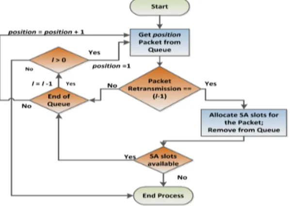
The sequence of super-frames in which a data packet is transmitted and retransmit-ted, is called an epoch. The maximum duration of an epoch is limited by the number of allowed retransmissions, R. In the end of the Rth retransmission, the data packets that could not be received are dumped from the queue.
3.1.1 Medium Access Control Protocol
A maximum number of MTs are accepted to form a group and share a set of time slots to send their data packets. The maximum number of MTs is defined by the MPR capability of the receiver. For the following sections, it will be considered a maximum ofJ MTs per group, and the same time duration for all data packets.
3.1.1.1 Random Access Mode
The satellite starts by allocating the RA slots, according to bandwidth and QoS require-ments, for the initial transmission of the MAC data packets. The RA slots are grouped in sets ofn0slots to each packet, carrying theirn0redundant copies. The number of different
packets transmitted in the RA mode is N, given a total of N*n0 RA allocated slots per
super-frame. Figure 3.1 represents an example of two packets sent by each MT, where in each slot is sent a copy of the correspondent packet.
Figure 3.1: RA packet transmission.
3.1. SYSTEM CHARACTERIZATION 31
In order to maintain the energy and bandwidth efficiency, the n0 value must be
care-fully planned. Also the maximum throughput of the system, limited by (N∗J)/T, should be higher than the total load,λJ, whereλdenotes the average packet generation rate per MT, to guarantee stability.
3.1.1.2 Scheduled Access Mode
After the initial transmission, the satellite gets to know that P MTs transmitted in the initial RA slots of an epoch. This allows the satellite to choose the values from n0 tonR,
in which the data transmission is optimized.
In case of unsuccessful transmission in the initial RA slots, or generalizing, after the RA slots of the super-frame l, the SA mode schedules the necessary SA slots, limited to what is left of theBmaxslots of the super-frame, to retransmit the data packets in thel+1
super-frame.
The number of retransmissions is limited by R, so the maximum length of an epoch is R plus the initial transmission. If the data packets are successfully received before the Rth retransmission, the epoch ends as well. After the Rth retransmission, the remaining data packets are dropped.
In the SA mode, the total number of slots allocated to a data packet in thelth super-frame of an epoch, is given by n(P) =
n0, n1(P), ..., nR(P)
.
Due to the high RTT value for a satellite network, and in the presence of delay requirements to guarantee QoS for the traffic class that is being used, theR value cannot be too high. So, R should be below ⌊τmax/T⌋, where τmax is the maximum delay value,
and ⌊argument⌋ represents the floor function, which returns the maximum integer below
or equal to the function argument.
The throughput can also be limited by the availability of enough SA slots to transport all traffic. A super-frame has Bmax−(N ∗n0) time slots to allocate SA slots.
3.1.2 Multipacket Reception Receiver Structure
32 CHAPTER 3. SR-NDMA PROTOCOL DESCRIPTION AND QOS
PER was obtained in [GaDB+11] and is briefly described in this section.
Nodes contend for the channel at each epoch and as expected collisions might occur. A data block, of N symbols, transmitted by a user p, can be expressed, on the time domain, as {sn,p;n = 0, ..., N −1}, and its correspondent on the frequency domain as
{Sk,p;k= 0, ..., N−1}. At the receiver, at the frequency domain, the received signal from
multiple MT’s for a given transmission r is
Yk(r)=
P X
p=1
Sk,pH(
r)
k,p+N
(r)
k , (3.1)
where Hk,p(r) is the channel response for the pth MT at the rth transmission. Nk(r) is the channel noise for the rth transmission. The total number of slots allocated to an epoch until the l+ 1th super-frame for P MT’s is given by ζl(P) =
l P
i=0
n(iP). Considering that
P MTs transmit ζl(P) times and 0 ≤ l ≤ R, then the received ζl(P) transmissions are characterized as follows
Yk = HTkSk+Nk (3.2)
=
Hk,(1)1 . . . Hk,P(1)
..
. . .. ...
H(ζ
(P)
l )
k,1 . . . H
(ζl(P)) k,P
Sk,1
.. . Sk,P +
Nk(1)
.. .
N(ζ
(P)
l ) k
For a given MTp, the estimated signal at the frequency domain is
˜
Sk,p =
Fk,p(1) ... F(ζ
(P)
l )
k,p
Yk=FTk,pYk . (3.3)
Fk,p corresponds to the feedforward coefficients of the proposed system, and these are
chosen to minimize the mean square error 2σ2E
k,p for a MT p. Considering that Γp =
[Γp,1 = 0, . . . ,Γp,p= 1, . . . ,Γp,P = 0]T, 2σ2Ek,p is evaluated as follows
2σEk,p2 = Eh|S˜k,p−Sk,p|2 i
= FTk,pHTk −Γp
ESkSHk
FTk,pHTk −Γp H
+FTk,pENkNHk
F∗
3.1. SYSTEM CHARACTERIZATION 33
Regarding Eh|Sk,p|2 i
= 2σ2
S and E
N
(r) k
2
= 2σ2
N, the optimal Fk,p is obtained by
applying the method of Lagrange multipliers to (3.4), which results1
Fk,p=
HHkHk+
2σN2
2σ2 S
Iζ(P) l
−1
HHkΓp
1− 1 2N σ2
S
. (3.5)
From (3.4) and (3.5) results
σp2 = 1
N2
N−1 X
k=0 E
S˜k,p−Sk,p
2
. (3.6)
The structure from the receiver is represented in figure 3.2.
Figure 3.2: Receiver structure [PBD+13].
For a QPSK constellation and being Q(x) the well known Gaussian error function, the Bit Error Rate (BER) of a given userp is
BERp ≃Q
1
σp
. (3.7)
For an uncoded system with independent and isolated errors, the PER for a fixed packet size of M bits is
P ERp ≃1−(1−BERp)M. (3.8)
1It should be noted that σ2
s and σ2N denote the variance of the real and imaginary parts of Sk,p and
N(r)
![Figure 2.3: Classification of techniques applied for MPR [LSW12].](https://thumb-eu.123doks.com/thumbv2/123dok_br/16581742.738574/48.892.140.756.238.531/figure-classification-techniques-applied-mpr-lsw.webp)
![Figure 2.4: S-NDMA scheme signal [GaBD + 12].](https://thumb-eu.123doks.com/thumbv2/123dok_br/16581742.738574/52.892.202.697.124.421/figure-s-ndma-scheme-signal-gabd.webp)

![Table 3.1: Main statistics values assumed for the VoIP call generation [GL08][DSM04].](https://thumb-eu.123doks.com/thumbv2/123dok_br/16581742.738574/68.892.228.672.131.398/table-main-statistics-values-assumed-voip-generation-dsm.webp)