Engineering
ISSN: 1809-4430 (on-line)
_________________________
1 Engº A grônomo, Prof. Doutor, Faculdade de Ciências A grárias, Universidade Federal de da Grande Dourados, Dourados – M S,
Fone: (67) 3410-2388, [email protected]
2 Engenheira Agrônoma, Profª Doutora, Colégio Agrícola Dom Agostinho Ikas, São Lourenço da M ata-PE,
3 Engº A grícola, Prof. Doutor, Departamento de Engenharia de Biossistemas, ESALQ/USP, Piracicaba – SP, [email protected] 4 Engº A grônomo, Prof. Doutor, Departamento de Engenharia de Biossistemas, ESALQ/USP, Piracicaba – SP, [email protected]
PRESSURE COMPENSATING MICROSPRINKLERS USING MICROTUBE AS A FLOW CONTROLLER
Doi:http://dx.doi.org/10.1590/ 1809-4430-Eng.Agric.v36n1p 36-45/2016
ALEXSANDRO C. DOS SANTOS ALMEIDA1, CERES D. G. C. DE ALMEIDA2,
TARLEI A. BOTREL3, JOSÉ A. FRIZZONE4
ABSTRACT: Microsprinkler non-pressure compensating nozzles usually show water flow variation along the lateral line. This study aimed at adapting micr otubes into non-c ompe nsating system of microsprinklers previous installed in the field, as a self-compensated nozzle, to improve the flow uniformity along the lateral line. Microtubes were adapted to three types of commercial microsprinklers. Tests were conducted, both in the laboratory and in field, to evaluate the microsprinkler performance at four different flows (40, 50, 60 and 70 L h-1) under pressure head range from 75 to 245 kPa. Nozzles presented coefficient of flow-rate variation (CVq) lower than 5.5% and distribution uniformity (DU) greater than 95%, which are classified as excellent. The original spatial water distribution of the microsprinkler did not change by using microtube as a nozzle. This device adapted to non-pressure compensating microsprinklers are functional and operate effectively with flows ranging up to 70 L h-1. Small variations at microsprinkler flows along the lateral line can occur, however, at random manner, which is common for pressure-compensating nozzles. Therefore, the microtube technique is able to control pressure variation in microsprinklers.
KEYWORDS: microtube nozzles, micro- irrigation, lateral design.
MICROASPERSORES AUTOCOMPENSANTES UTILIZANDO MICROTUBOS COMO DISPOSITIVO DE CONTROLE DA VAZÃO
RESUMO: Microaspersores convencionais, geralmente, apresentam variação de vazão ao longo das linhas laterais. O objetivo deste trabalho foi adaptar microtubos a microaspersores não compensantes (instalados em campo) no intuito de melhorar a uniformidade de emissão de vazão ao longo da linha lateral. Microtubos foram adaptados a três modelos comerciais de microaspersores. Testes foram conduzidos em laboratório e em campo para avaliar o desempenho em quatro diferentes vazões: 40; 50; 60 e 70 L h-1 com pressões variando de 75 a 245 kPa. No geral, os emissores avaliados apresentaram coeficiente de variação de vazão (CVq) menor que 5,5% e uniformidade de distribuição maior que 95%. Esses resultados de uniformidade de emissão ao longo da linha lateral são classificados como excelentes. Microtubos atuando como bocal compensante em microaspersores convencionais, já em uso no campo, operaram eficientemente nos microaspersores com vazões de até 70 L h-1 e não alteraram o padrão original de distribuição espacial de água. Pequenas variações da vazão, ao longo da linha lateral, podem ocorrer, porém de forma aleatória, o que é comum em emissores autocompensates devido ao CV de fabricação, indicando que a técnica de microtubos é eficiente no contr ole da variação de pressão e m m icroaspersores não auto-com pensantes.
INTRODUCTION
The rapidly increasing water demand from the domestic, agriculture and industrial sectors has been led farmers to use water resources efficiently in irrigated crops. Therefore, it is necessary to look for irrigation systems and management technologies that may improve water application. Microirrigation systems have been adopted in many farmers due to its potential to increase water use efficiency. These irrigation systems have been recorded as one which provides high irrigation water uniformity, maintaining a favourable root-zone water balance (SILVA et al., 2013). On the other hand, such uniformity might be affected by several factors including hydraulic design, manufacturing variation, temperature effects and clogging (DOGAN & KIRNAK, 2010; VERAMIYA et al., 2011; MATTAR et al., 2014).
Spatial variation in operating pressures is one of the major reasons that causes non-uniform water distributions in micro- irrigation systems (WU et al., 2010; DOGAN & KIRNAK, 2010), after land slope and lateral line length (WU et al., 2010; ZANG et al, 2013). With that, the use of non-pressure compensating nozzles consists in an alternative to achieve acceptable flow variations; these systems have a maximum pressure head variation of 20% found in the irrigation sector (BOMAN, 2007). This criterion limits lateral line lengths and diameters; however, it allows reaching water flow variations below 10% and obtaining a good uniformity (> 80%). An alternative to perform longer lateral lines is using pressure-compensating nozzles (LI et al., 2007).
Pressure compensating nozzles are used to maintain constant water flow along lateral lines, even though different inlet pressures are applied. They are commonly used in crops which require high water distribution uniformity, on uneven terrains and when longer lines are needed (WU et al., 2010; PINTHONG et al., 2013). Several pressure-compensating devices are used to prevent variations; however, most of them consist of a diaphragm with holes in the middle. These diaphragms works by stretching according to pressure applied, controlling the hole size and, consequently, water flows. The greater is the inlet pressure the smaller is the water outlet (LI et al., 2007). In the bottom line, it is used a flexible piece that moves or extends to block or release water flow. Like any moving parts, they end up wearing. Furthermore, pressure-compensating nozzles have the disadvantage of being more expensive and sensitive to chemicals than non-pressure compensating ones.
Microtube of 0.5 to 1.5 mm of inside diameter can work as water flow controller in micro-irrigation (DONAG & KIRNAK, 2010). They compensate variations on inlet pressure of the nozzle by varying the length and diameter of microtubes along lines (KELLER et al., 2001). Eve n though simple, they have enabled longer lines and a high uniformity of distribution. SOUZA et al. (2009), SOUZA et al. (2011), ALVES et al. (2012) obtained greater evenness in irrigation distribution by using microtubes with double diameters and lengths in drip irrigation systems of crop fields and orchards.
observed a small random variation in nozzle flows, the uniformity was excellent (statistical uniformity coefficient greater than 95%). All researches were made for new irrigation systems.
To turn an old micro- irrigation system with no-compensate nozzles into a pressure compensate one, it is necessary to replace all nozzles by self-compensated pressure ones. This study has the aim to adapt a microtube, as a self-compensated nozzle, into non-pressure compensating commercial microsprinklers previous installed in the field to improve water flow uniformity along lateral lines.
MATERIAL AND METHODS
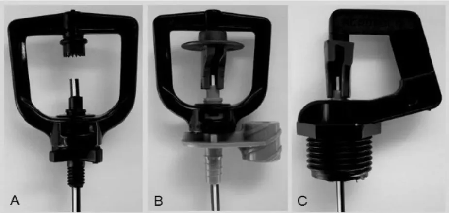
To develop the experiment, we have chosen three commercial models of micro-sprinklers (without self-compensating pressure) that have been used in Brazilian farms. We then adapt microtubes into nozzles, turning them into a self-compensating microsprinkler. We named them as "A", "B" and "C" models (Fig. 1). For the model "A", two different configurations were used (wetted diameter), given as A1 and A2. Added to this, we evaluated the perfor mance of this irrigation system through both laboratory and field tests. Finally, we also evaluated the uniformity of flow distribution along the laterals lines and their respective spatial distribution.
FIGURE 1. Microsprinkler models using microtube as nozzle to compensate pressure variation. Commercial microsprinkler from different brands (A, B and C) and types.
Laboratory Experime nt
Laboratory trials were carried out at the College of Agriculture “Luiz de Queiroz”, Universidade de São Paulo (University of São Paulo), in Brazil. It was defined the relationship among pressure, flow and length, to observe the suitable wetted diameter. The study was carried out using a test apparatus built in the Pump Testing Laboratory of the Department of Hydraulic and Water Engineering. The experimental set-up consisted of a centrifugal pump, a 120-mesh disc filter, flow-control valves, bypass pipe for regulating flow within system and maintaining it constant each evaluation. Pressure head was maintained at constant levels during each test through a pressure-regulating valve. An electronic manometer was attached to the lateral lines to record the pressure. As flow of water passes through microtube, a measuring bottle was kept at a lower level of the microtube to catch water. Tests under laboratory conditions were conducted with no wind.
Based on the method of trial-and-error, pressure and length were established under nominal flow and longer wetted diameter or the nearest that informed by manufacturer (Table 1). For each run, flow and wetted diameter were measured. Experimental pressure head of the different microsprinkler models was measured and compared to those obtained by the equations of Darcy-Weisbach and Blasius.
Microsprinkler flows were measured by weighing water collected over one minute with six repetitions using a precision balance (±0.01 g). We assumed water density as 1 g cm-3, since viscosity effects can be neglected when flow is fully turbulent. As a result, temperature changes do not cause major dimensional changes in the flow passageway (SENYIGIT et al., 2012).
TABLE 1. Microsprinkler operation characteristic informed by manufacturer.
Model Flow rate (L h-1) Pressure (kPa) Wetted diameter (m)
A 88 150 3.4 - 4.9
B 88 150 8.4
C 112 150 6.8
A single linear equation (Eq. 1) was used to project the system to the field by calculating microtube length based on required pressure. Table 2 shows these equations for each model used.
L =
a×
H ˗b
(1)where,
L is the length of the microtube (cm); H is the pressure (kPa) at each nozzle;
a
andb
are equation parameters.TABLE 2. Experimentally determined pressure-length equations.
Model Flow (L h-1) Equation R2
A1 40 L = 0.2920×H ˗ 10.316 0.9994
A2 50 L = 0.2003×H ˗ 10.932 0.9976
B 60 L = 0.1362×H ˗ 8.9376 0.9912
C 70 L = 0.1205×H ˗ 15.522 0.9735
The determination coefficients of pressure- length relationships were higher than 0.97, which represents high accuracy. Deposit spatial distribution was measured by 441 catch cans spaced each 0.3 m. Each can water content was measured after one hour of irrigation. Model A spatial distribution could not be evaluated since it has a jet distribution pattern instead of spray.
Design procedure
Head loss was calculated in each lateral line segment (n), from downstream end of the pipe to upstream by step-by-step procedure - SbS (Eq. 2). The maximum lateral line length, limited by maximum allowed variation, was obtained by subtraction of maximum and minimum experimental pressure. Calculations of head loss for each line segment were executed in a computer worksheet.
loc n 1 n 2 n n 1 n
n (Z Z ) H
2g D
SeV f H
H (2)
where,
Hn is the inlet pressure head of each nozzle (m);
Hn-1 is the inlet pressure head from the previous nozzle (m);
fn is the friction factor within each segment (dimensionless); Se is the nozzle spacing (m); Vn is the flow speed through each segment (m s-1);
D is the diameter of the pipe (m);
Hloc is the local loss protrusion nozzle barb (m).
The friction head losses were calculated using the Darcy-Weisbach equation (Eq. 3). At each step, the Reynolds number (Re) was calculated to use the proper friction factor equation (fn). In some downstream segments of the lateral lines where laminar flow occurred, Re ≤ 2,000, fn is given by:
n n
Re 64
f (3)
where,
Ren is the Reynolds Number (dimensionless) in the considered segment between nozzles. On the other hand, Blasius equation (Eq. 4) was used on those segments where turbulent and transitional flows have occurred, Re > 2,000. In general, transitional regime is considered like turbulent regime (CARRION et al., 2013), because it is usual to find laterals with less than 60 nozzles, which means that effect of the laminar and transitional regime can occur. In this study, at maximum two segments of each lateral line was found in transitional regime, as a result Blasius equation could be used.
25 . 0 n n
Re 0.316
f (4)
Local losses were measured according ZITTERELL et al. (2014) mainly for this diameter pipe and kind of barb (Eq. 5), based on obstruction index equation and on low effect of Reynolds Number. These local losses can become significant compared to the overall energy loss.
2g V 0.2074 hf
2 n (n)
Loc (5)
An optic projector measured the actual mean internal diameter of the lateral pipeline with six replications (13.074 mm).
Field experime nt
Field experiments were carried out in a lateral line laid on an even terrain to observe the pressure head variation along lateral. Pressure gauges were fitted at the upstream and downstream ends to record pressures values. Water volume of each nozzle was collected during three minutes (Fig. 2) and weighted in a precision balance (±0.01 g). The water temperature was recorded to account water specific weight. Four different experimental configurations were tested (Table 3).
The uniformity distribution was evaluated by the low quarter distribution uniformity (DU) and statistical uniformity (Us). Both coefficients were used as indicators for evaluations of nozzle performance in delivering water to plants, following classification criteria proposed by BRALTS (1986).
q q 100
DU lq (6)
where,
qlq is the average of the lowest quarter of the nozzle flows (L h-1) and q is the mean nozzle flow (L h-1).
1 CVq
100
Us (7)
where,
CVq is the coefficient of flow-rate variation.
TABLE 3. Experimental values of hydraulic parameters of microsprinkler irrigation with microtubes.
Hidraulic parameters A1 A2 B C
Slope (%) 2.76 2.83 2.77 2.99
Maximum pressure (kPa) 245 245 245 245
Minimum pressure (kPa) 75 93 96 149
Lateral lenght (m) 68 58 50 40
Nozzles 34 29 25 20
RESULTS AND DISCUSSION
FIGURE 3. Rainfall (water distribution) in microsprinkler model B and C.
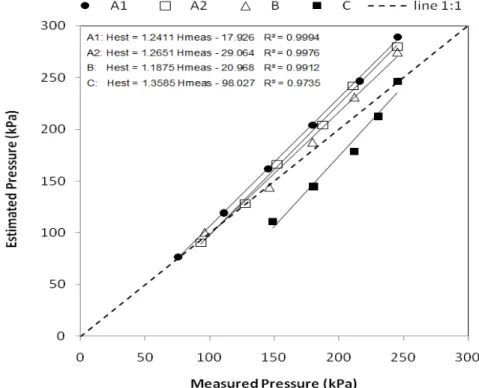
Measured and estimated pressures by Darcy-Weisbach and Blasius equations (Fig. 4) showed good agreement and low variability; therefore, the model gives a good prediction to pressure-length relationship. For most of the microsprinklers, it was observed small overestimation of the measured pressure in around 10% with high accuracy (R2 > 0.98). On the other hand, for microsprinkler model C, it was observed an underestimation in measured pressure of 11 %. This can be attributed to the overestimation of the operation pressure o f these models, which were overestimated the head loss. Moreover, the model equation used for microsprinkler model C nozzle underestimated the head loss on the lateral line, which has the average flow equal to the mean operating flow laboratory-estimated (Table 4). Furthermore, coefficient of flow-rate variation (CVq) were lower than 5.5% and acceptable (SOUZA et al., 2009; VEKARIYA et al., 2011; ZHANG et al., 2013; MATTAR et al., 2014). This low variation is similar to pressure-compensating nozzles (LI et al., 2007).
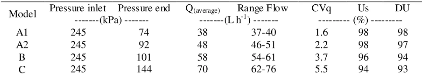
TABLE 4. Field experiment results.
Model Pressure inlet Pressure end Q(average) Range Flow CVq Us DU ---(kPa) --- ---(L h-1) --- --- (%) ---
A1 245 74 38 37-40 1.6 98 98
A2 245 92 48 46-51 2.2 98 97
B 245 101 58 54-61 3.7 96 94
C 245 144 70 62-76 5.5 94 93
We could classify as Type II-profile (a downward-sloped lateral), the relation between pressured head versus length position for all microsprinkler models. It occurs when the lateral line is on downslope, where a gain of energy by slopes at downstream points is greater than the energy dropped by friction. However, the pressure at the end of the line is still less than the inlet pressure and the minimum pressure is located somewhere along the line between the half and the end of line (LI et al., 2007). Lateral lengths and nozzle number, in this study, were similar to those reported by BOMAN (2007) at flow analogous aiming to obtain a maximum variation of flow around of 5%. Increasing nozzle flow reduced the lateral line length. Nozzles with flow of 70 L h-1 (model C) latea line length was around 40 m (Fig. 5). Conversely, nozzles with flow of 40 L h-1 (model A1) the lateral length was 68 m.
The flow uniformity range recommended for US and DU coefficients is upper to 90% (BRALTS, 1986), which is considered excellent (Table 4). Thus, the system performed very well in delivering a uniform flow along the lateral line. It suggested that proposed equations could be used to microsprinklers with flows range from 40 to 70 L h-1.
The allowed variation of pressure on the lateral line was inversely proportional to the nozzle flow. Using nozzles with flows of 38 L h-1,the pressure range allowed was around 170 kPa (Table 4). Conversely, nozzle with flows of 70 L h-1,this range is about 100 kPa. These ranges are within recommended ranges by CARRION et al. (2013), where the magnitude of maximum range allowed on a lateral line must be less than 200 kPa. Higher flow rates require greater pressure to maintain high flow rate for lateral line using one microtube diameter. Lower pressures for high- flow nozzles might reduce lateral length, when only one diameter of microtube is used. Therefore, the lateral length can be extended using different diameters of microtubes (SOUZA et al., 2009; ALVES et al., 2012).
The flow application uniformity for A1, A2 and B nozzles by SU and DU coefficients were greater than 95%. For model C, the flow uniformity was 94 and 93 % for SU and DU, respectively, which according to general criteria by BRALTS (1986) is a good uniformity. Good flow uniformity was reached in previous field tests under conventional hydraulic design procedure neglecting local energy loss due to connection of nozzles; however, the flow tended to decrease to end stream.
Flow variations observed in microsprinklers tested occurred at random manner along the lateral line (Fig. 6). This characteristic is typical of the pressure-compensating nozzles (LI et al., 2007). Using non-pressure compensating nozzles these variation commonly shows a trend of reducing flow along the lateral (HEZARJARIBI et al., 2008).
FIGURE 6. Distribution of nozzle flow.
The results found are similar to many researches carried with new drip irrigation systems (SOUZA et al., 2009; ALVES et al., 2012) and new microsprinkler systems (ALMEIDA et al., 2009). However, our study assesses this technique in microsprinklers non-pressure-compensating nozzles already operating on farm.
CONCLUSIONS
Microtube as nozzle adapted to non-pressure compensating commercial microsprinkler, already installed in the field, are functional and operate effectively for microsprinklers with flows range up to 70 L h-1. Variations at microsprinkler flows along the lateral line occur at random manner that is common for pressure-compensating nozzles, suggesting that microtube technique suits to control the pressure variation in microsprinklers.
ACKNOWLEDGEMENTS
The main author want to thank the Foundation for Research Support of São Paulo (FAPESP) for his PhD and Master scholarship. The CNPq, FAPESP and the Ministry of Science and Technology for providing additional financial support through the National Institute of Science Engineering and Technology in Irrigation (INCTEI).
REFERENCES
ALVES, D.G.; PINTO, M.F.; SALVADOR, C.A.; ALMEIDA, A.C.S.; ALMEIDA, C.D.G.C; BOTREL, T.A. Modelagem para o dimensionamento de um sistema de microirrigação utilizando microtubos ramificados. Revista Brasileira de Engenharia Agrícola e Ambiental, Campina Grande, v.16, n.2, p.125-132, 2012.
BOMAN, B.J. Microsprinkler irrigation. In: LAMM, F.R.; AYARS, J.E.; NAKAYAMA, F.S. Microirrigation for crop production. Amsterdam: Elsevier, 2007. p.575-608
BRALTS, V.F. Field pe rformance and evaluation. In: NAKAYAMA, F.S.; BUCKS, D.A. (Ed.). Trickle of irrigation for crop production. Amsterdam: Elsevier, 1986. p.216-240
CARRION, F.; TARJUELO, J.M.; HERNANDEZ, D.; MORENO, M.A. Design of microirrigation subunit of minimum cost with proper operation. Irrigation Science, Heidelberg, v.31, n.5, p.1199-1211, 2013.
DOGAN, E., KIRNAK, H. Water temperature and system pressure effect on drip lateral properties.
Irrigation Science, Heidelberg, v.28, n.5, p.407-419, 2010.
HEZARJARIBI, A.; DEHGHANI, A. ; HELGHI, M.M.; KIANI, A. Hydraulic performance of various trickle irrigation nozzles. Journal of Agronomy, Fasialabad, v.7, n.3, p.265–271, 2008.
KELLER, J., ADHIKARI, D. L., PETERSEN, M. R., SURYAWANSHI, S. Engineering low-cost
micro-irrigation for small plots. Longmont: Journal of International Development Enterprises, 2001. (Report, 5).
LI, J., MENG, Y., LI, B. Field evaluation of fertigation uniformity as affected by injector type and manufacturing variability of nozzles. Irrigation Science, Heidelberg, v.25, n.2, p.117–125, 2007.
MATTAR, M; AL-AMOUD, A.; ATEIA, M. Impact of water temperature and structural parameters on the hydraulic labyrinth-channel nozzle performance. Spanish Journal of
Agricultural Research, Madrid, v.12, n.3, p.580-593, 2014.
PINTHONG, K.; MERKLEY, J.P.; CHITTALADAKORN, S. Flow path and hydraulic analysis for on- farm pressurized irrigation systems. Irrigation Science, Heidelberg, v.31, n.3, p.371–383, 2013.
SENYIGIT, U., CRUZ, R.L., RODRIGUEZ-SINOBAS, L.; SOUZA, W. J. Changes on nozzle flow under different water temperature and pressure. Journal of Food, Agriculture and
Environment, Helsink, v.10, n.3-4, p. 718-720, 2012.
SILVA, A.J.P.; COELHO, E.F.; MIRANDA, J.H. Efficiency of water application of irrigation systems based on microsprinkling in banana. Scientia Agricola. Piracicaba, v.70, n.3, p.139-146, 2013.
SOUZA, R.O.R.M.; MIRANDA, E.P.; NASCIMENTO NETO, J.R.; FERREIRA, T.T.S.;
MESQUITA, F.P. Irrigação localizada por gravidade em comunidades agrícolas do Ceará. Revista
Ciência Agronômica, Fortaleza, v.40, n.1, p.34-40, 2009.
SOUZA, W.J.; BOTREL, T.A.; ALMEIDA, A.C.S Modelo matemático aplicado à irrigação com microtubos sob regime de escoamento turbulento. Engenharia Agrícola, Jaboticabal, v.31, n.2, p.278-289, 2011.
VEKARIYA, P.B., SUBBAIAH, R., MASHRU, H.H. Hydraulics of microtube nozzles: a dimensional analysis approach. Irrigation Science, Heidelberg, v.29, n.4, p.341–350, 2011.
WU, P.T.; ZHU, D.L.; WANG. J. Gravity- fed drip irrigation design procedure for a single- manifold subunit. Irrigation Science, Heidelberg, v.28, n.4, p.359–369, 2010.
ZHANG, L.I.; WU, P.; ZHU, D. Hydraulic design procedure for drip irrigation submain unit based
on relative flow difference. Irrigation Science, Heidelberg, v.31, n.5, p.1065–1073, 2013. ZITTERELL, D.B; FRIZZONE, J.A.; RETTORE NETO, O. Dimensional analysis approach to estimate local head losses in microirrigation connectors. Irrigation Science, Heidelberg, v.32, n.3,