ScienceDirect
Available online at www.sciencedirect.com
Procedia Structural Integrity 17 (2019) 539–546
2452-3216 2019 The Authors. Published by Elsevier B.V. Peer-review under responsibility of the ICSI 2019 organizers. 10.1016/j.prostr.2019.08.072
10.1016/j.prostr.2019.08.072 2452-3216
© 2019 The Authors. Published by Elsevier B.V.
Peer-review under responsibility of the ICSI 2019 organizers.
ScienceDirect
Structural Integrity Procedia 00 (2019) 000–000
www.elsevier.com/locate/procedia
2452-3216 © 2019 The Authors. Published by Elsevier B.V. Peer-review under responsibility of the ICSI 2019 organizers.
ICSI 2019 The 3rd International Conference on Structural Integrity
Fatigue behavior of different geometry scaffolds for bone
replacement
R. Baptista
a,b,*, M. Guedes
a,ca CDP2T and Department of Mechanical Engineering, Setúbal School of Technology, Instituto Politécnico de Setúbal, 2910-761 Setúbal, Portugal
bIDMEC, Escola Superior de Tecnologia de Setúbal, Instituto Politécnico de Setúbal, 2910-761 Setúbal, Portugal cCeFEMA, Instituto Superior Técnico, ULisboa, Av. Rovisco Pais, 1049-001 Lisboa, Portugal
Abstract
When transplanting bone tissue is not a possibility, tissue engineering is responsible for developing solutions to substitute the functions of the missing bone structure or support the process of bone regeneration. Scaffolds can be used to fulfill this mission by supporting loads that were applied to the missing bone, supporting the cell regenerating process, allowing for the necessary nutrients and oxygen diffusion and delivering growth factors or drugs. Scaffold geometry design must support static and dynamic loads up to 20 MPa in order to replace human trabecular bone. Also, it should generate macro and micro pores to support cell growth and mineral precipitation, while all pores should be interconnected for nutrient and oxygen diffusion. Scaffolds were fabricated according to ASTM-695 standard, using two different layouts, 50% porosity and a theoretical distance of 0.8 mm between each filament. A 400 m diameter nozzle was used, and scaffolds were produced at 215 ºC with deposition rate of 30 mm/s. Both designs were fatigue tested until 3600 cycles, using different load amplitudes and a frequency of 0.25 Hz. The orthogonal scaffold showed improved behavior, with compression modulus reaching 680 MPa, when a maximum stress of 14.5 MPa was applied.
© 2019 The Authors. Published by Elsevier B.V.
Peer-review under responsibility of the ICSI 2019 organizers. Keywords: Bone regenerations; Scaffolds; 3D printing; Fatigue
* Corresponding author. Tel.: +351-265-790-000; fax: +351-267-790-043. E-mail address: ricardo.baptista@estsetubal.ips.pt
Nomenclature
A Specimen apparent cross section area ΔL Specimen height variation
E Apparent compressive modulus ε Normal Strain
σ Normal Stress
1. Introduction
Tissue engineering was defined in the National Science Foundation workshop in 1988 O’Brien (2011). It aims for the development of biological substitutes in order to restore, maintain or improve a tissue function. When the need for trabecular bone replacement arises, there are only two viable options. The first one are bone grafts, but unfortunately supply limitation, risk of rejection or donor site morbidity and rate of failure, limit the performance of the current gold standard. The second one is the implant strategy. Implants can be made out of metal, with long implantation life, but high rigidity, lack of integration and fatigue and fracture risk. Other innovative approach is the use of biocompatible polymeric materials, such as poly(lactic-acid) (PLA) or poly(caprolactone) (PCL). These materials have lower rigidity then metals, and overall mechanical properties closer to those of trabecular bone Roseti et al. (2017).
When replacing trabecular bone, implants are typically used in the form of a porous scaffold. Scaffolds toil as carriers for cell cultures and/or drugs that improve and control cell growth, in order to regenerate tissue. Scaffolds must also be capable of withstanding mechanical loads while regeneration takes place. An ideal scaffold should be biocompatible and non-immunogenic, reducing rejection risk; biodegradable and absorbable, in order to be gradually replaced by bone tissue; and osteoconductive, shaping the final geometry of the regenerated tissue. Scaffolds structural features are also important: a high level of porosity and pore interconnectivity is mandatory, allowing for cell oxygenation and nutrient diffusion Guduric et al. (2017). Rosenzweig et al. (2015) have determined an optimal pore size of 300-350 μm for the penetration of osteoblast cells in implants. Finally, mechanical properties are fundamental to scaffold’s overall performance, and should match the reported 2-12 MPa for trabecular bone strength and 50-500 MPa for trabecular bone compressive modulus Li et al. (2017).
On the other hand, in recent years 3D printing has been proving to be a versatile route to scaffolds manufacture. From the several additive manufacturing (AM) techniques, fused filament fabrication (FFF) is one of the most promising for that purpose. FFF 3D printers are widely available, and their commercial prices are still dropping. One of the major advantages when using FFF to produce scaffolds is the elimination of the use of organic solvents, required to remove polymeric part support structures in other techniques. A possible toxicity source is thus avoided. Other advantages include the ability to produce highly complex, customized, biomimetic structures, providing the necessary microenvironment for cell adhesion and growth. Still some disadvantages remain, such as the long time requirement to print complex geometries and the lack of resolution to print very small scaffolds design details Anh-Vu et al. (2015). Geometry design is very important for final scaffold performance.
In the described context, the aim of this study is to assess the static and fatigue behavior of 3D printed PLA scaffolds, aiming to evaluate the possibility of using them for trabecular bone replacement.
2. Materials and Methods
2.1. Scaffolds
Scaffolds for trabecular bone replacement were first designed using the slicing freeware Cura (Ultimaker) as a 12.7x12.7x25.4 mm block. Instead of removing a standard shape from a master volume, the geometries were draw by adding struts in a predetermined layer pattern Gregor et al. (2017). No outer walls or bottom and top layers were used, only the infill pattern was considered in order to generate a uniformly spaced scaffold, with 100% pore interconnectivity. For a 50% porosity scaffold, a strut spacing of 800 μm was obtained. As no other geometric parameters were available for configuration, the two initial layers design were extracted from the g-code and repeated
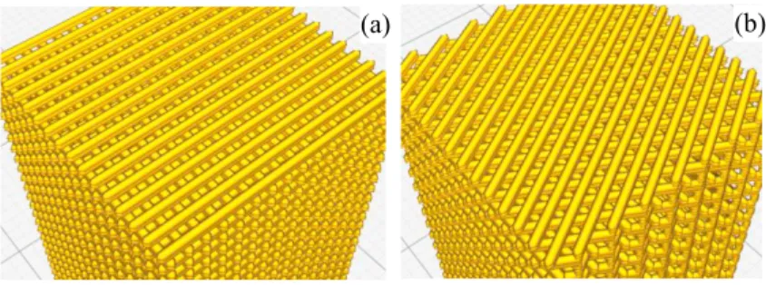
in order to generate different scaffolds, labelled 2xOrtho and 2xIsometric. 2xOrtho scaffolds used a double layer configuration, where the same layer is repeated twice before being rotated by 90º (Figure 1a). In the orthogonal scaffold thus obtained all layers share the same support points. The scaffold main pore size is about 400 μm. 2xIsometric scaffolds also use a double layer configuration, but with 60º rotation (Figure 1b). The final pattern is 0º/60º/120º, reducing the size of the scaffold main pores, as changing pore shape from square to trapezoidal. The isometric configuration maintains the common support points, while changing the pore geometry.
Fig. 1. 3D model layout for 3D printing of (a) 2xOrtho and (b) 2xIsometric scaffolds.
2.2. 3D printing
PLA (DoWire) spooled filament with 1.75 mm was used in the manufacturing of all scaffolds, printed using a Blocks Zero (Blocktec) 3D printer. The printer uses a 400 μm diameter nozzle, without heated bed. All scaffolds were printed at room temperature using the same manufacturing parameters (Table 1). Those parameters were optimized for scaffold mechanical performance.
Table 1. Scaffold 3D printing manufacturing parameters. Specimen Temperature (ºC) Speed (mm/s) Layer Thickness (μm) Offset (μm) Angle (º) 2xOrtho 215 30 200 800 0/90 2xIsometric 0/60/120 2.3. Microscopy
The produced scaffolds were characterized regarding their morphological features, pattern defects, final pore dimension and overall compliance to projected dimensions using optical microscopy (Olympus BHM 112B) and scanning electron microscopy (SEM) (Hitachi S2400). Samples for SEM observation were previously coated with Au-Pd alloy to assure adequate electrical conductivity. Image analysis was carried out using the ImageJ freeware (https://imagej.nih.gov/ij/).
2.4. Mechanical Testing
Scaffolds mechanical performance was assessed using static and dynamic tests. Monotonic strain-stress curves for scaffold compression were obtained in an electromechanical test machine (TS300, Impact Test Equipment). Deformation rate was set at 1 mm/min, and scaffold compression was applied until deformation reached 40 % of the initial length. Both scaffold configurations were tested in order to assess the effect of scaffold geometry upon yield stress, maximum compressive load and apparent compressive modulus. Strain ε was calculated as the coefficient between scaffold length variation ΔL and scaffold initial length. Apparent stress σ was calculated as the applied load
F divided by the total area A of specimen’s apparent cross section (12.7x12.7 mm2). The apparent compressive
modulus was obtained as the slope of the linear portion of the σ-ε curve.
Dynamic fatigue testing was carried out using the same electromechanical test machine. Low cycle fatigue (LCF) loading was carried out with 0.25 Hz frequency, and stress ratio R of 0.1 under compression. Maximum test duration was set to 3600 cycles, and specimen height, deformation energy and apparent compressive modulus were recorded in real time. Deformation energy was determined as the σ-ε hysteresis loop area, and the apparent compressive modulus as the slope of the linear portion of the σ-ε curve. Four different stress levels were considered for both scaffold configurations. Maximum applied stress was chosen as a function of the maximum stress obtained for the monotonic tests. For 2xOrtho scaffolds maximum stress level of 9.1, 10.9, 12.8 and 14.5 MPa were applied, while for 2xIsometric scaffolds maximum stress level of 9.0, 10.5, 12.0 and 13.6 MPa were applied. All fatigue tests were carried out under stress control.
3. Results and Discussion
3.1. Characterization of Scaffolds Structure
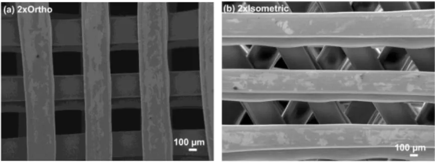
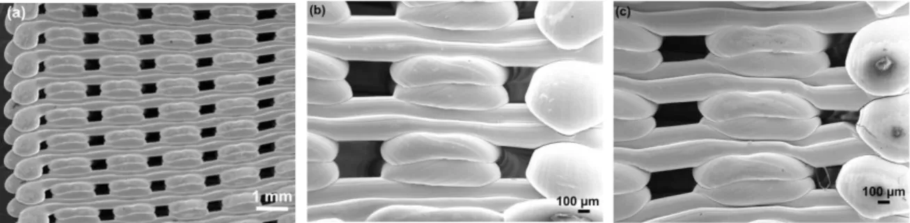
Figures 2a) and 2b) show low magnification images of 2xOrtho and 2xIsometric scaffolds, respectively. In orthogonal scaffolds the measured printed strut thickness was 411.0 21.6 µm, in good agreement with dimensions of the used extrusion nozzle (approx. 3 % larger, which was attributed to polymer deformation during cooling to room temperature). However, the printed filament thickness in isometric scaffolds was only 304.6 22.6 µm, i.e., around 24 % lower than the used nozzle diameter. Nevertheless, the average weight of produced isometric samples was only 4.5 % lower than the average weight of orthogonal specimen, suggesting that isometric printed filament height is higher than orthogonal extruded filament. Similar pore cross-sectional area was determined in the studied geometries, corresponding to 0.15 0.01 mm2 in orthogonal scaffolds and to 0.14 0.01 mm2 in isometric scaffolds.
Fig. 2. Low magnification images of the printed scaffolds before mechanical testing (front view): (a) 2xOrtho geometry; and (b) 2xIsometric geometry.
3.2. Scaffolds Mechanical Testing
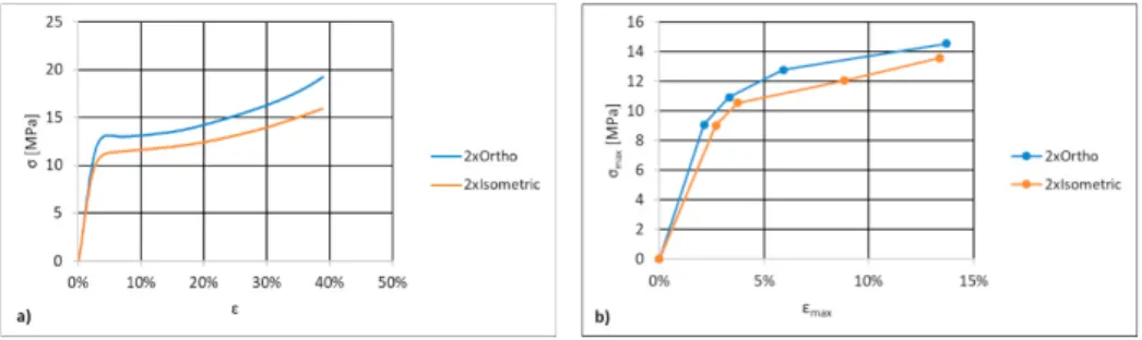
Scaffolds compression static tests rendered monotonic behavior on both geometrical configurations (Figure 3a). An initial region of linear elastic behavior is followed by a nonlinear elastoplastic zone. The transition occurs around 4% deformation and corresponds to a yield strength of 12.9 MPa and 10.8 MPa for 2xOrtho and 2xIsometric scaffolds, respectively. Over the 40 % maximum deformation the 2xOrtho scaffolds achieved a maximum strength of 19 MPa, while the 2xIsometric scaffold only reached 16 MPa (around 15 % lower). These results are in line with the values reported by Yan et al. (2019) using 3D printed PLA scaffolds with a strut spacing of 1 mm, while Rodrigues et al. (2016) obtained higher values, using 650 μm strut spacing. As for the scaffolds apparent compressive modulus, values of 510 MPa and 441 MPa were respectively obtained for 2xOrtho and 2xIsometric scaffolds. Gong et al. (2017) obtained similar apparent compressive modulus values for different pore geometries in 3D printed scaffolds, therefore using square or circular pores apparently doesn’t affect the overall scaffold mechanical behavior. When comparing the behavior of PLA materials Rosenzweig et al. (2015) have also obtained similar compressive modulus for 700 μm strut spacing PLA scaffolds.
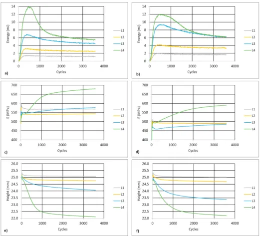
When subjected to 4 different load cycles using constant stress amplitudes (L1 = 4.1 MPa; L2 = 4.9 MPa; L3 = 5.7 MPa; L4 = 6.5 MPa, for 2xOrtho and L1 = 4.1 MPa; L2 = 4.7 MPa; L3 = 5.4 MPa; L4 = 6.1 MPa for 2xIsometric scaffold), the maximum stress and strain values can be used to build the scaffolds cyclic curve (Figure 3 b). The resulting plots cover a maximum deformation of 15 %. Direct comparison shows that the cyclic curve is below the monotonic curve for strain values lower than 7 %, an indication of cyclic softening when scaffolds are subjected to small deformation. Over a total of 3600 cycles, the area of the hysteresis loop was calculated and recorded. Figure 4 a) and b) show the deformation energy evolution along the fatigue life of the 2xOrtho and 2xIsometric scaffolds, respectively. The deformation energy can be calculated from the hysteresis loop area, and measures the irreversible deformation introduced in the scaffold in a given cycle. This energy is spent on the formation of defects and released as heat Senatov et al. (2016). The deformation energy increases very rapidly in the first 400 cycles and is proportional to the applied stress amplitude. This corresponds to an initial accumulated deformation, that tends to stabilize after 1000 cycles. This behavior can also be seen on Figures 4 e) and f), where the specimen height over the cycle test is represented for the 2xOrtho and 2xIsometric scaffolds respectively. In the first 1000 cycles specimen height is reduced due to irreversible accumulated deformation. As the deformation energy tends to stabilize, the height reduction rate also reduces. For the lower stress amplitude loadings, specimen height was almost constant after 1000 cycles, while the deformation energy was also constant and lower than 4 mJ. The maximum stress applied to the specimens was lower than the yield stress (Table 2). For higher stress level, the decreasing deformation energy during loading corresponds to cyclic hardening of the material, Senatov et al. (2016), but the initial maximum values lead to the higher height reduction of 3.3 mm and 3.2 mm for the 2xOrtho and 2xIsometric scaffolds, respectively. Changes in the apparent compressive modulus result from a balance between the rate of defect accumulation, reducing the modulus, and pore collapse, increasing the modulus, Senatov et al. (2016). Figure 4 c) and d) show the evolution of the apparent compressive modulus for both the 2xOrtho and 2xIsometric scaffolds, suggesting that that balance is dominated by pore collapse, which leads to an overall modulus increase. For all loading cycles the apparent compressive modulus is higher than the static modulus, on both scaffold layouts. For lower stress amplitudes the modulus is constant, because the specimen height is also constant, and no more pores are collapsing. Increasing stress amplitude leads to decreasing specimen height, because of pore collapsing and defect accumulation. As height decreases, and more pores collapse, the apparent compressive modulus increases, reaching a value of 680 MPa for the 2xOrtho scaffold and 589 MPa for the 2xIsometric scaffold. This behavior is opposite to what happens in real trabecular bone, as discussed by Michel et al. (1993).
Fig. 3. Compressive σ-ε curves for 2xOrtho and 2xIsometric scaffolds: (a) monotonic and b) cyclic loading.
Table 2 summarizes the obtained results, showing that the 2xOrtho scaffolds present an overall improved static and dynamic mechanical performance. Different authors have studied the geometry design influence on the mechanical properties of the scaffold. Moroni et al. (2006) studied the differences between orthogonal and 0º/45º oriented scaffolds, but the lack of strut support alignment reduces the mechanical performance due to bending between supports. Gleadall et al. (2018) suggested that the 0º/60º/120º strut orientation allows to solve this problem, because all layers share the same strut support points. In as much, applied loads can be transferred between layers without bending, increasing the scaffold strength and compressive modulus. Those authors also suggest that the increased contact area between layers on the isometric and hexagonal geometry should increase strength and elastic modulus. However this doesn’t agree with results in the current work, nor in Korpela et al. (2012). The 2xIsometric scaffolds
showed lower strength and decreased apparent compressive modulus in both static and dynamic tests. This is maybe a result of layer misalignment or layer debonding, requiring further investigation.
Fig. 4. Deformation energy for a) 2xOrtho and b) 2xIsometric scaffolds; apparent compressive modulus for c) 2xOrtho and d) 2xIsometric scaffolds; and specimen height for e) 2xOrtho and f) 2xIsometric scaffolds, after 3600 fatigue cycles.
Table 2. Dynamic cycling scaffold behavior summarized by maximum stress, apparent compressive modulus, specimen height and maximum strain after 3600 cycles.
Specimen Max Stress (MPa) E (MPa) Energy (mJ) Height (mm) Max Strain (%)
2xOrtho 9.1 569 1.324 25.071 2.1 10.9 543 2.475 24.756 3.3 12.8 577 4.672 24.067 5.9 14.5 680 5.380 22.114 13.7 2XIsometric 9.0 491 1.731 25.016 2.7 10.5 490 3.433 24.692 3.7 12.0 485 6.289 23.386 8.8 13.6 589 6.286 22.203 13.4
3.3. Scaffold Structure After Cyclic Loading
There are four main type of scaffold defects introduced by fatigue loading, as reported by Senatov et al. (2016) and Gong et al. (2017). Shear deformation, crack growth, delamination and breaking of layers. Analysis of scaffolds
structure after cyclic loading suggests that the main degradation mechanism in the produced samples is shear deformation. Figure 5 a) shows a side view of a deformed 2xOrtho scaffold after 3600 cycles under maximum applied stress of 14.5 MPa and stress ratio of 0.1, showing non-uniform deformation. In fact, in some regions deformation appears to be normal to loading direction (Figure 5b), leading to a pore height around 350 μm after deformation compared to the designed pore height of 400 μm (approx. 12.5 % reduction of the lateral pore height). In other regions shear deformation appears to prevail. Figure 5c shows shear acting upon the strut, with formation of wrinkles and strut bending where microcracks can initiate and propagate Senatov et al. (2016). It should be noted that even after 3600 loading cycles no delamination or breaking of layers was found. Scaffold layers firmly adhered to each other during the 3D printing process and bonding apparently was not affected by fatigue loading.
Fig. 5. Low magnification images of 2xOrtho scaffolds (side view) after 3600 cycles at 14.5 MPa maximum stress: a) general view; b) sample region where normal deformation appears to dominate; c) sample region where shear deformation appears to dominate.
4. Conclusions
This work shows that 3D printing with PLA is useful to manufacture scaffolds for trabecular bone replacement. Using optimized printing parameters two different scaffold layouts were produced, characterized and fatigue tested. The orthogonal configuration offers an overall better mechanical performance. An apparent compressive modulus of 510 MPa and a strength of 19 MPa, when a 40% monotonic compression is applied, are viable properties for trabecular bone replacement. When cyclic loading is applied the apparent compressive modulus increased up to 680 MPa, as dynamic loading behavior is dominated by pore collapse. The only detected fatigue damage mechanism was shear deformation. Even after 3600 loading cycles, no debonding or micro cracking was found. The isometric layout is characterized by a smaller pore, which can increase cell adhesion, but the overall mechanical properties are about 13% inferior when compared to the orthogonal scaffolds.
Acknowledgements
This work was supported by FCT, through IDMEC, under LAETA, project UID/EMS/50022/2019 and CeFEMA under contract Pest-OE/CTM/UI0084/2014.
References
Anh‐Vu, Do, Khorsand Behnoush, Geary Sean M., and Salem Aliasger K. (2015). “3D Printing of Scaffolds for Tissue Regeneration Applications.” Advanced Healthcare Materials 4(12):1742–62.
Gleadall, Andrew, Dafydd Visscher, Jing Yang, Daniel Thomas, and Joel Segal. (2018). “Review of Additive Manufactured Tissue Engineering Scaffolds: Relationship between Geometry and Performance.” Burns & Trauma 6(1):19.
Gong, Baoming, Shaohua Cui, Yun Zhao, Yongtao Sun, and Qian Ding. (2017). “Strain-Controlled Fatigue Behaviors of Porous PLA-Based Scaffolds by 3D- Strain-Controlled Fatigue Behaviors of Porous PLA- Based Scaffolds by 3D-Printing Technology.” Journal of Biomaterials Science, Polymer Edition (51305295):1–9.
Gregor, Aleš, Eva Filová, Martin Novák, Jakub Kronek, Hynek Chlup, Veronika Blahnová, Martin Barto, Alois Ne, Jan Ho, Matěj Buzgo, Veronika Blahnová, Věra Lukášová, Martin Bartoš, Alois Nečas, and Jan Hošek. (2017). “Designing of PLA Scaffolds for Bone Tissue
Replacement Fabricated by Ordinary Commercial 3D Printer.” Journal of Biological Engineering 11(1):1–21.
Guduric, Vera, Reine Bareille, Simon Latour, and Agathe Gr. (2017). “Characterization of Printed PLA Scaffolds for Bone Tissue Engineering Characterization of Printed PLA Scaffolds for Bone Tissue Engineering.” (November).
Korpela, Jyrki, Anne Kokkari, Harri Korhonen, and Minna Malin. (2012). “Biodegradable and Bioactive Porous Scaffold Structures Prepared Using Fused Deposition Modeling.” 610–19.
Li, S., A. Zahedi, and V. Silberschmidt. (2017). “Numerical Simulation of Bone Cutting: Hybrid SPH-FE Approach.” Numerical Methods and Advanced Simulation in Biomechanics and Biological Processes 187–201.
Michel, Markus C., Xiang Dong E. Guo, Lorna J. Gibson, Thomas A. McMahon, and Wilson C. Hayes. (1993). “Compressive Fatigue Behavior of Bovine Trabecular Bone.” Journal of Biomechanics 26(4–5):453–63.
Moroni, L., J. R. De Wijn, and C. A. Van Blitterswijk. (2006). “3D Fiber-Deposited Scaffolds for Tissue Engineering : Influence of Pores Geometry and Architecture on Dynamic Mechanical Properties.” 27:974–85.
O’Brien, Fergal J. (2011). “Biomaterials & Scaffolds for Tissue Engineering.” Materials Today 14(3):88–95.
Rodrigues, Natacha, Matthew Benning, Ana M. Ferreira, Luke Dixon, and Kenny Dalgarno. (2016). “Manufacture and Characterisation of Porous PLA Scaffolds.” Pp. 33–38 in Procedia CIRP. Vol. 49.
Rosenzweig, Derek H., Eric Carelli, Thomas Steffen, Peter Jarzem, and Lisbet Haglund. (2015). “3D-Printed ABS and PLA Scaffolds for Cartilage and Nucleus Pulposus Tissue Regeneration.” (July).
Roseti, Livia, Valentina Parisi, Mauro Petretta, Carola Cavallo, Giovanna Desando, Isabella Bartolotti, and Brunella Grigolo. (2017). “Scaffolds for Bone Tissue Engineering: State of the Art and New Perspectives.” Materials Science and Engineering C 78:1246–62.
Senatov, F. S., K. V. Niaza, A. A. Stepashkin, and S. D. Kaloshkin. (2016). “Low-Cycle Fatigue Behavior of 3d-Printed PLA-Based Porous Scaffolds.” Composites Part B: Engineering 97:193–200.
Szojka, Alexander, Karamveer Lalh, Stephen H. J. Andrews, Nadr M. Jomha, Martin Osswald, and Adetola B. Adesida. (2017). “Biomimetic 3D Printed Scaffolds for Meniscus Tissue Engineering.” Bioprinting 8(April):1–7.
Yan, Yufei, Hao Chen, Hongbo Zhang, Changjun Guo, Kai Yang, and Kaizhe Chen. (2019). “Vascularized 3D Printed Scaffolds for Promoting Bone Regeneration.” Biomaterials 190–191(August 2018):97–110.