Serviceability limit state related to excessive lateral
deformations to account for inill walls in the
structural model
Estado limite de serviço de deformações horizontais
excessivas com a consideração das alvenarias de
preenchimento no modelo estrutural
a Universidade Federal de Santa Maria, Departamento de Estruturas e Construção Civil, Santa Maria-RS, Brasil; b Universidade Federal de Santa Maria, Programa de Pós-Graduação em Engenharia Civil, Santa Maria-RS, Brasil.
Received: 03 Dec 2014 • Accepted: 25 Mar2015 • Available Online: 12 Jun 2015
Abstract
Resumo
Brazilian Codes NBR 6118 and NBR 15575 provide practical values for interstory drift limits applied to conventional modeling in order to prevent negative effects in masonry inill walls caused by excessive lateral deformability, however these codes do not account for inill walls in the struc-tural model. The inclusion of inill walls in the proposed model allows for a quantitative evaluation of strucstruc-tural stresses in these walls and an assessment of cracking in these elements (sliding shear diagonal tension and diagonal compression cracking).
This paper presents the results of simulations of single-story one-bay inilled R/C frames. The main objective is to show how to check the service-ability limit states under lateral loads when the inill walls are included in the modeling. The results of numerical simulations allowed for an evalu-ation of stresses and the probable cracking pattern in inill walls. The results also allowed an identiicevalu-ation of some advantages and limitevalu-ations of the NBR 6118 practical procedure based on interstory drift limits.
Keywords: inilled frames, masonry inill walls, diagonal strut model, inite element method, serviceability limit states.
Para evitar efeitos negativos em walls de vedação produzidos pela deformabilidade horizontal excessiva, a NBR 6118 e a NBR 15575 apresen-tam valores práticos de limites de deslocamentos horizontais aplicados à modelagem convencional (sem a consideração das walls de preenchi-mento no modelo estrutural). Entretanto, a inclusão das walls no modelo permite a avaliação quantitativa das tensões solicitantes nas alvenarias de preenchimento e a avaliação da ocorrência de issuras nas mesmas (por cisalhamento, tração diagonal ou compressão diagonal).
Neste trabalho são apresentados resultados de simulações numéricas de quadros de concreto armado considerando a presença da alvenaria de preenchimento. O objetivo principal do trabalho é demonstrar como pode ser realizada a veriicação do estado limite de serviço produzido por ações horizontais quando as walls são incluídas na modelagem. Os resultados das simulações permitiram a avaliação das tensões solicitantes e do provável tipo de issuração nas alvenarias. Os resultados também permitiram identiicar algumas vantagens e limitações do procedimento prático da NBR 6118 em termos de deslocamentos limites.
Palavras-chave: pórticos preenchidos, alvenarias de preenchimento, modelo de diagonal equivalente, método dos elementos initos, estados
limites de serviço.
G. M. S. ALVA a
[email protected] J. KAMINSKI JR a
[email protected] G. MOHAMAD a
[email protected] L. R. SILVA b
1. Introduction
Masonry inill walls in building frame structures are normally con-sidered only as gravity loads applied to the main structure. In other words, the stiffness of these walls is overlooked in models of structural analysis. When ixed to the concrete frame structure, inill walls act as resistant elements to lateral loads of the building. However, it is not a current design practice in Brazil to consider masonry panels in the structural model for verifying Limit States of the structure.
There are few Brazilian studies on the structural behavior of ma-sonry-inilled frames subjected to lateral loads. Alvarenga [1] car-ried out a theoretical and experimental study of steel frames with concrete masonry inills, while Santos [2], Tanaka [3] and Madia [4] focused on numerical simulations in concrete buildings.
On the other hand, there is an extensive international literature on the behavior of concrete and steel framed structures with masonry inill walls. Research in this area began to draw interest more than four decades ago, much of it focusing on analyses to respond to seismic loads. Briely, three types of research contributions related to this subject are described below.
The irst contribution is related to macromodeling research, which investigates the utilization and improvement of diagonal-strut mod-els.A number of important studies have been published since the 1970s. Relevant studies among the more recent of these include, Asteris et al. [5], Chrysostomou and Asteris [6], El-Dakhakhni et al. [7], Amato et al. [8], Doudoumis [9], Crisafulli and Carr, [10] and
Uva et al. [11]. The second line of research is related to utilization
and improvement of micromodeling, in which the structure and ma-sonry are modeled with plane or spatial elements via the inite ele-ment method, including the case of openings in the walls. Some of the more recent relevant studies include Doudoumis [12], Mondal and Jain [13], Asteris [14], Ghosh and ADSM [15], Mohyeddin et al. [16], Stavidris and Shing [17], Baloevic et al. [18] and
Koutro-manos et al. [19]. The third research contribution is comprised of
a vast number of specialized publications focusing on experimen-tal investigations. Among these, some noteworthy studies include those of Mehrabi et al. [20], Durrani and Haider [21], Flanagan and
Bennett [22], Al-Chaar et al. [23], Asteris et al. [24], Tasnimi and
Mohebkhah [25] and Liu and Manesh [26].
According to FEMA 306 [27], FEMA 274 [28] and FEMA 356 [29] guidelines, there are speciic detailed procedures for analyzing concrete and steel frames with masonry inill walls. Chapter 8 of FEMA 306 [27] summarizes the main studies on the topic and presents equations for obtaining equivalent strut width for panels without openings and for obtaining strength capacity of the equiva-lent diagonal strut with regard to possible failure modes. These guidelines have been widely cited in related international studies over the last 15 years.
The Brazilian norms NBR 6118 [30] and NBR 15575 [31] provide interstory drift limits under service conditions for preventing nega-tive effects on seals produced by excessive interstory drift ratio. These limits are practical values to be applied in conventional modeling (without accounting for inill walls as resistant elements) and are a simple way to minimize lateral deformability of the struc-ture, regardless of the mechanical characteristics of the wall. Evidently, the above-mentioned veriication does not allow a quan-titative evaluation of stresses in the masonry panels, nor does it account for geometric inluences (dimensions, openings) or
me-chanical characteristics of the walls. This evaluation can only be performed if the stiffness of the masonry panels is included in the structural model. With an assessment of stresses in the masonry panels, it is possible to examine the occurrence of possible failure modes (cracking) in walls subjected to lateral loads: by shear, by diagonal tension or by diagonal compression.
The main objective of this study is to demonstrate a way of verify-ing the service limit state produced by lateral loads when inill walls are included in the structural model. Numerical examples were car-ried out, using the equivalent diagonal strut method (DSM) and a
Table 1 – Analytical equations for obtaining
the equivalent strut width
Authors Equation
Mainstone [32]
a
0
,
175
.
( )
0,4.
D
H −
λ
=
Hendry [34]2
a
2 v 2 p+
a
a
=
λ
π
=
a
.
2
p v v.
2
λ
π
=
a
ap = contact length between column and masonry wall;
av = contact length between beam and masonry wall. Liauw e Kwan [35]
( )
H0,95.sen 2θ
a=
.D
2 λ
Decanini e Fantin [36]Uncracked panels: 85 , 7 H£ l : D . 748 , 0 085 , 0 a
H ÷÷ø ö çç è æ l + = 85 , 7 H> l : D . 393 , 0 130 , 0 a
H ÷÷ø ö çç è æ l + = Uncracked panels: 85 , 7 H£ l : D . 707 , 0 010 , 0 a
H ÷÷ø ö çç è æ l + = 85 , 7 H> l : D . 470 , 0 040 , 0 a
H ÷÷ø ö çç è æ l + = Paulay e
Priestley [37]
4
D
a
=
Durrani e Luo [38]
D . 2 sen . a=g q
( )
0,1p p 4 h . I. E . mH.Et. . 2 sen . 32 , 0 -÷ ÷ ø ö ç ç è æ q = g ÷ ÷ ø ö ç ç è æ p + = L . I. E .E I..H . 6 1 . 6 m p p v v
Ev = elasticity modulus of the beam;
Iv = second moment of area of the beam.
Chrysostomou
e Asteris [6]
a
0
,
270
.
( )
.
D
model that employs the inite element method (FEM). The compari-son between acting stresses and strength capacity of the walls al -lowed to make inferences with regard to the integrity of the walls in the face of possible failure modes (cracking) and evaluate the ap -propriateness of the practical drift limit values of the NBR 6118 [30] for conventional modeling. FEMA 306 guidelines [27] were used to calculate equivalent strut width and masonry strength parameters.
2. Evaluation of stiffness and strength
capacity of masonry panels
2.1 Diagonal strut model
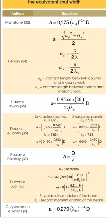
The most widely used model for simulating the contribution of masonry panels to the stiffness of framed structures under lateral loads is the equivalent strut model, which entails the introduction of pin-jointed diagonal struts with axial stiffness calculated from the mechanical and geometric properties of the walls and from the elements that compose frame structures (beams and columns). The key parameter for obtaining this axial stiffness is equivalent strut width, which can be obtained using the analytical equations proposed by a number of authors in the specialized literature and presented in item 2.2 and summarized in Table 1.
In a linear elastic analysis, with data for thickness and longitudinal elastic modulus of the wall, the problem consists of determining the width of the cross section bar that simulates the presence of the wall. In other words, it is necessary to ind the axial stiffness of the diagonal equivalent strut, which produces effects similar to that of the real structure.
The main advantage of the equivalent diagonal strut model is its simplicity, making it an attractive alternative for structural design purposes.
2.2 Equations for calculating equivalent diagonal strut
This item presents the formulation for obtaining equivalent diago -nal strut (only one single-strut element), according to the special-ized literature, for panels under lateral loads.
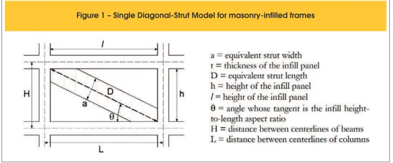
Figure 1 illustrates the dimensions involved in the equivalent di-agonal strut model for masonry-inilled frames.
Most of the formulas found in the literature employ the parameter of relative stiffness of the frame to the inill (λ), calculated by:
(1)
where
E = modulus of elasticity of the masonry panel; Ep = modulus of elasticity of the column;
Ip = second moment of area of the column; t = thickness of the inill panel;
h = height of inill panel (see Figure 1);
θ = slope of the inill diagonal to the horizontal (see Figure 1). As a matter of nomenclature, it is useful to express the product of relative stiffness (λ) and height between beam axes (H) as:
(2)
Table 1 presents equations for the case of walls without openings. These equations are discussed in Asteris et al. [5].
There are usually considerable differences observed between the values obtained through the equations in Table 1. The equa-tion proposed by Mainstone [32] is the most well-known and is included in normative guidelines of FEMA 306 [27], FEMA 274 [28], FEMA 356 [29] and in Al-Chaar [33]. However, this equation, when compared to the others, supplies the lowest values for equivalent diagonal strut width, as emphasized in Asteris et al. [5] and Chrys -ostomou and Asteris [6].
For the case of walls with openings, there are two analytical equa -tions for the purposes of a global analysis. Al-Chaar [33] proposes a reduction factor for the width obtained by Mainstone’s equation
[32], as a function of the relation between the opening area and the area of the wall without openings, regardless of the position of the opening in the masonry panel:
(3)
where
R is the width reduction factor; Aop is the area of opening;
Ainill is the area of inill panel (without opening).
Mondal and Jain [13] proposed a simple equation to obtain a simi-lar reduction factor, but applicable only to central openings:
(4)
However, as underlined in Asteris [14], the position of the openings exerts a good deal of inluence on the lateral stiffness of the panel-frame structure, underlining the need for calibration in models that employ plane or tridimensional inite elements.
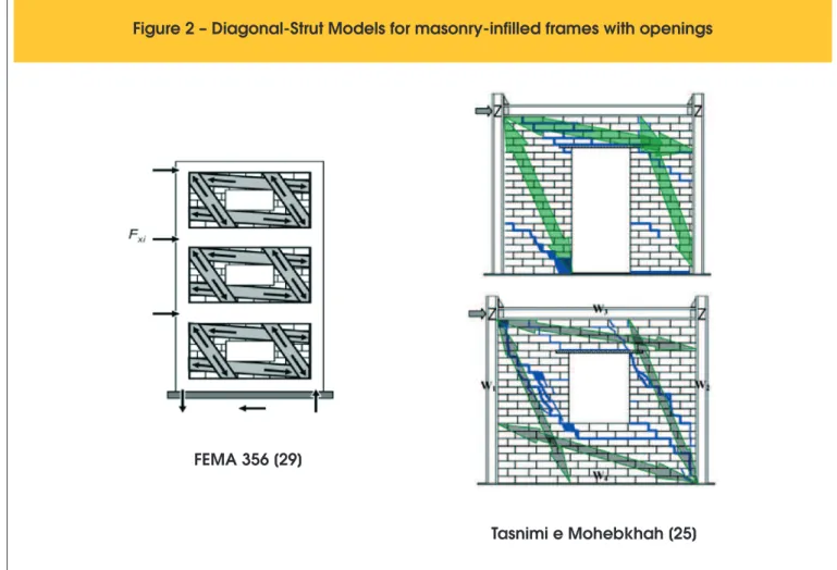
Another model that can be used is the equivalent diagonal model dein-ing compression struts to account for existent opendein-ings, as suggested in FEMA 356 [29] and Tasnimi and Mohebkhah [25] and illustrated in Figure 2. In this case, the equivalent widths of diagonal struts can be evaluated from the dimensions of the portions of the wall that are separated by the openings. However, to obtain equivalent diagonal strut width with greater precision, the ideal evaluation would employ the FEM.
2.3 Equations for evaluation of the strength
capacity of inill panels (stresses)
This item presents equations for calculating the strength capacity of inill walls (stresses), which were used in the analyses via FEM in item 4. Strength capacity was extracted from FEMA 306 guidelines [27].
2.3.1 Shear Strength of the inill – fv
According to Equation 8-4 of FEMA 306 [27], lateral load on the wall that produces sliding-shear failure (FRv) can be evaluated by:
(5)
Figure 2 – Diagonal-Strut Models for masonry-infilled frames with openings
FEMA 356 [29]
where
l and t are respectively the length and the thickness of the inill panel;.
fv is the shear strength (average) of the inill panel, which follows the Coulomb criterion:
(6)
being
τ0 = cohesive capacity of the mortar beds;
µ = coeficient of sliding friction along the bed joint; σ = vertical compressive stress in the wall.
The vertical stress σ results from the self-weight of the panel and the compression vertical component imposed on the wall by the panel-frame interaction (distortion cause by the lateral loads). The axial compressive force in diagonal strut is obtained by:
(7)
The vertical component of the resultant diagonal compression is obtained by:
q
=
q
q
=
q
F
.
tg
cos
.
sen
F
sen
.
D
Rv Rv RvThus, stress σ at the average height of the wall can be calculated by:
t.l
W
.
5
,
0
t.l
tg
.
F
Rvq
+
alv=
s
where Walv is the self-weight of the panel.
Knowing that
t.
l
F
f
Rvv
=
, compression vertical stress σ can berewritten as:
(8)
being σg the compression vertical stress due to the self-weight of the panel.
From Equations 8 and 6:
(
v g)
0
v
.
f
.
tg
0
,
5
.
f
=
t
+
m
q
+
s
Isolating fv, leads to the equation of masonry shear strength:
(9)
In the absence of experimental results, cohesion can be obtained by:
(10)
where fc,0 is the strength of masonry in the horizontal direction, which, according to FEMA 306 [27], can be considered 50% of the stacked prism strength (fp).
Thus, cohesion can be obtained simply by:
(11)
2.3.2 Diagonal Tension Strength of the inill – ft,θ
FEMA 306 [27] recognizes, in item 8.3.1, that masonry tensile strength depends on the angle of tensile principal stresses in rela-tion to the bed joints. In the absence of experimental results, ma -sonry tensile strength can be obtained according to Equation 8-12 of FEMA 306 [27]:
(12)
Thus, diagonal tension strength can be obtained simply by:
(13)
2.3.3 Diagonal Compression Strength of the inill – fc,θ
Based on Equation 8-10 of FEMA 306 [27], diagonal compression strength assumed for the panel is:
(14)
Thus:
(15)
2.4 Equations for evaluating the strength capacity
of inill panels
(diagonal forces)
2.4.1 Shear strength of the inill – DRv
The axial force strength in the equivalent diagonal strut associated to sliding-shear failure is the same as that presented in Equation 7:
q
=
cos
F
D
RvRv
where FRv is the lateral load on the wall that produces sliding-shear
failure, which can be obtained with the formulation presented in Equations 5 to 11.
2.4.2 Diagonal tension ttrength of the inill – DRt
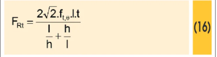
According to Equation 8-11 of FEMA 306 [27], lateral loads on the wall that produce diagonal tensile failure (FRt) can be evaluated by:
(16)
where
ft,θ is the diagonal tension strength of the panel, calculated accord -ing to item 2.3.2.
l, h and t are geometric parameters of the wall, as shown in Figure 1.
Thus, the axial force strength in the equivalent diagonal strut as-sociated to diagonal tensile failure of the wall is obtained by:
(17)
2.4.3 Diagonal compression strength of the inill – fc,θ
According to Equation 8-10 of FEMA 306 [27], lateral loads on the wall that produce diagonal compression failure (FRc) can be evalu
-ated by:
(18)
where
a is equivalent strut width; t is wall thickness;
fc,θ is diagonal compression strength.
FEMA 306 [27] considers that diagonal compression strength is equal to strength of masonry in the horizontal. Thus, axial force strength in the equivalent diagonal strut associated to diagonal compression failure is obtained by:
(19)
3. Methodology and modeling
Numerical simulations were performed in this study to analyze sin-gle-story one-bay inilled frames. Each reinforced concrete frame was composed of two columns and two beams.
In order to include the masonry panels as resistant elements, di -agonal strut (DSM) models using plane stress state inite elements (see Figure 3) were employed. For the diagonal strut structural
Figure 3 – Models used for modelling of the frame and infill-panel elements
analysis, a software program for solving plane frames was utilized. The equivalent strut width was calculated according to Mainstone’s equation [32] (see Table 1). To account for beam-column nodes dimensions, rigid-end-offsets in beams and pillars were deined ac -cording to NBR 6118.
Analysis of inilled frames via FEM was performed using the ANSYS program. The element PLANE182 was used for modeling both the
concrete structure and the inilled frame. This inite element pos -sesses four nodes, each with two degrees of freedom: translation in nodal X and Y directions (the XY plane, in this case, being the plane of the inilled frame). In terms of discretization, 10cm x 10cm inite elements were deined and, as needed, 5cm x 5cm elements. The elements CONTAT171/TARGE169 were used to account for the possibility of contact, separation and sliding between concrete frame structures and inill walls, in the surface-to-surface contact simu-lation. Normal contact stiffness factor (FKN) values were found for
each model, not only in regard to numeric convergence but also to the stabilization of values for contact pressure and penetration among surfaces. In all the models, the maximum penetration between con-crete frame structures and masonry was lower than 0.1mm. Friction between the concrete structure and the wall was considered using the
Coulomb model, limiting the maximum contact friction to α.fv. A value
of α = 1.5 was adopted to convert average (conventional) shear stress on the wall to shear stress in the inite element.
Initially, lateral loads were applied to produce interstory drifts equal to H/850 in the models with no walls. These forces were reapplied in the models with walls to analyze stresses in the masonry panels, in order to verify their stress level when two consecutive stories are subjected to the drift limit recommended by NBR 6118 [30]. In all the analyses, the materials were considered isotropic and of an elastic-linear behavior. A material linear analysis was employed because of the stress level applied to inilled frames (correspond-ing to service conditions of the structure). The materials were con -sidered isotropic because of simulations carried out by Doudoumis [12], which showed the insigniicant effects of the orthotropy of the wall on the behavior of the inilled frames with L/H > 1.5.
4. Numeric simulations
4.1 Example 1: Inilled frames without openings
In this example, four masonry-inilled frames were analyzed. The
theoretical span of the beams(L) was set at 6.0m and the distance between the beam axes (H) was set at 3.0m. The columns present -ed rectangular cross sections with the following dimensions (cm): 20x40, 20x60, 20x80 and 20x100. The rectangular cross section of the beams was set at 20x60. A 28.000 MPa longitudinal elastic
modulus was assumed for the concrete structure, corresponding to a concrete with compressive strength of C25. The inill walls were 20cm in thickness and a value of 1.50 MPa was assumed for stacked prism strength (fp). The longitudinal elastic modulus of the
wall (E) was obtained from the NBR 15812 equation [39] (E=600.
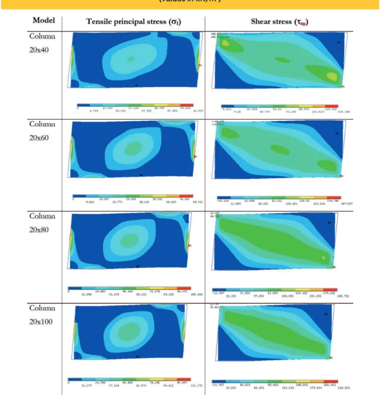
Figure 5 – Acting stresses related to diagonal tension and shear in infill walls – FEM models
2
fp). A value of µ = 0.7 was considered for the coeficient of friction between the concrete structure and the inill frame.
Results and conclusions of the simulations
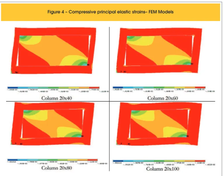
Figure 4 presents diagrams of the compressive principal elastic strains for the four inilled frames and shows the deformed shapes of the frames. It is possible to conirm the occurrence of separation between the concrete structure and the inill wall in certain places and the formation of struts in regions of contact.
Figures 5 and 6 show, respectively, the results for stresses related to diagonal tension, shear and diagonal compression. In the FEM results, σ1 is the tensile principal stress, τxy is the shear stress at the plane of the wall and σ3is the compressive principal stress. Table 2 shows a summary of the results presented in Figures 5 and 6 (FEM) and the results obtained with the diagonal strut model. It is important to note that in Table 2, the values for σ3 were extracted at a distance of 10 cm from the internal contour of the concrete frame structures, in order to prevent the extraction of values owing to the concentration of stresses. Extraction of the tensile principal stresses σ1 and shear stresses τxy proceeded in a similar way.
The main indings for this example are:
n The greater the stiffness of the column, the greater the stress
imposed in the inill walls, even when the interstory drift ratio is the same. This is an important aspect for the designer to consider, since even when complying with interstory drift limits recommended in design norms for conventional modeling, it is possible for walls ixed to framed structures with robust col-umns to suffer damage under elevated stresses.
n In the models with 20cmx80cm and 20cmx100cm columns,
cracking would have occurred had the frame structures been subjected to the interstory drift ratio limits from NBR 6118 (1/850 rad) for conventional modeling. Greater caution is therefore recommended in employing the interstory drift limit of H/850 to columns with signiicantly greater stiffness than that of the beams. In this case, modeling of the walls, even in single-story one-bay inilled frames, can provide approximate information as to their stress level.
n The expected failure modes occurred by diagonal tension and
shearing, while diagonal compression failure did not occur. Act-ing axial forces for the diagonal strut model were between 31% and 40% of the compressive axial force strength (diagonal
Figure 6 – Acting stresses related to diagonal compression in infill walls – FEM models
2
compression). In the FEM, the maximum compressive principal stresses were between 50% and 79% of the diagonal com-pression strength of the inill.
Observations on determining diagonal strut width
As mentioned in item 2.2, there are usually considerable differ-ences among the values provided by the diagonal strut width equa -tions from Table 1. For this example, width values obtained from the different equations were calculated and summarized in Table 3. For structural design purposes, it is more important to evaluate the differences in terms of interstory drifts and internal forces (espe -cially the latter, in order to predict the failure modes in the panels).
Table 2 – Summary of the results of the Example 1 – Maximum Internal Forces (Stresses) vs. Strength
(Forces in kN and stresses in kN/m
2)
Model Diagonal tension Shear Diagonal compression Probable type of failure Column 20x40
DSM DSd = 34,44
DRt = 46,80
DSd = 34,44 DRv = 83,56
DSd = 34,44
DRc = 111,51 Does not occurs
FEM s1 = 21,00
ft,q= 37,50
τxy = 75,00
a.fv= 102,86
s3 = 374,00
fc,q= 750,00 Does not occurs
Column 20x60
DSM DSd = 44,56
DRt = 46,52
DSd = 44,56 DRv = 82,35
DSd = 44,56
DRc = 121,85 Does not occurs
FEM s1 = 32,00
ft,q= 37,50
τxy = 93,00
a.fv= 104,52
s3 = 490,00
fc,q= 750,00 Does not occurs
Column 20x80
DSM DSd = 49,97
DRt = 46,23
DSd = 49,97 DRv = 81,22
DSd = 49,97
DRc = 128,41 Diagonal tension
FEM s1 = 40,00
ft,q= 37,50
τxy = 128,10
a.fv= 106,37
s3 = 540,00 fc,q= 750,00
Diagonal tension/ Shear
Column 20x100
DSM DSd = 53,07
DRt = 45,90
DSd = 53,07 DRv = 80,19
DSd = 53,07
DRc = 132,63 Diagonal tension
FEM s1 = 44,00
ft,q= 37,50
τxy = 120,00
a.fv= 108,44
s3 = 592,00 fc,q= 750,00
Diagonal tension/ Shear
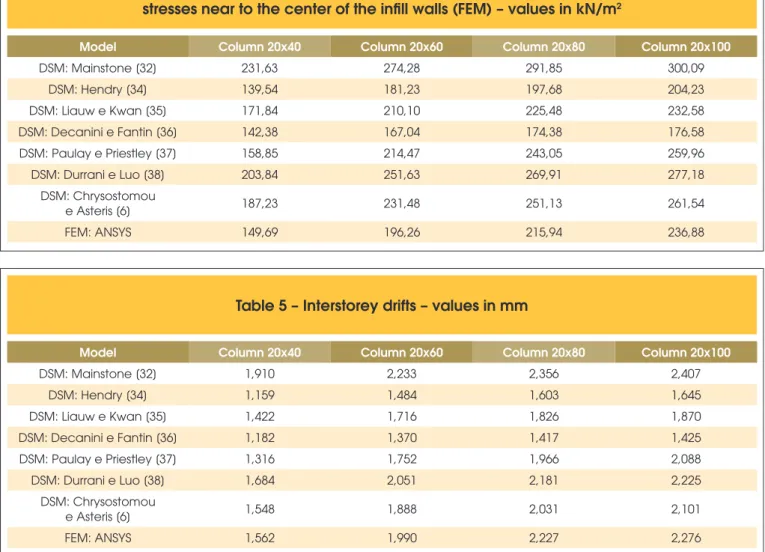
Table 4 shows the average compression stress in equivalent di -agonals struts (obtained from the ratio between compressive axial force and diagonal strut cross section area). Table 4 also shows compressive principal stresses near the center of the wall obtained by FEM (see Figure 6), for comparison with the compression prin -cipal stresses obtained by DSM. Table 5 shows values for relative lateral delections between beam axes for both models (DSM and FEM).
Despite the considerable differences in diagonal strut width val -ues shown in Table 3, such differences were not found in regard to stresses, which can be noted from the results shown in Table 4. For this example, Mainstone’s equation [32] gave the greatest diagonal strut compression stress values, thus proving to be the most conservative. The Liauw and Kwan equation [35] gave stress
Table 3 – Equivalent strut width - values in cm
Equation Column 20x40 Column 20x60 Column 20x80 Column 20x100
Mainstone [32] 74,34 81,23 85,61 88,42
Hendry [34] 186,61 203,72 222,21 241,27
Liauw e Kwan [35] 133,52 154,07 169,99 182,95
Decanini e Fantin [36] 180,95 234,37 278,76 316,17 Paulay e Priestley [37] 152,32 147,73 143,18 138,65
Durrani e Luo [38] 97,55 102,67 108,93 115,34
Table 4 – Compressive average stresses (DSM) and compressive principal
stresses near to the center of the infill walls (FEM) – values in kN/m
2Model Column 20x40 Column 20x60 Column 20x80 Column 20x100
DSM: Mainstone [32] 231,63 274,28 291,85 300,09
DSM: Hendry [34] 139,54 181,23 197,68 204,23
DSM: Liauw e Kwan [35] 171,84 210,10 225,48 232,58 DSM: Decanini e Fantin [36] 142,38 167,04 174,38 176,58 DSM: Paulay e Priestley [37] 158,85 214,47 243,05 259,96 DSM: Durrani e Luo [38] 203,84 251,63 269,91 277,18
DSM: Chrysostomou
e Asteris [6] 187,23 231,48 251,13 261,54
FEM: ANSYS 149,69 196,26 215,94 236,88
Table 5 – Interstorey drifts – values in mm
Model Column 20x40 Column 20x60 Column 20x80 Column 20x100
DSM: Mainstone [32] 1,910 2,233 2,356 2,407
DSM: Hendry [34] 1,159 1,484 1,603 1,645
DSM: Liauw e Kwan [35] 1,422 1,716 1,826 1,870
DSM: Decanini e Fantin [36] 1,182 1,370 1,417 1,425 DSM: Paulay e Priestley [37] 1,316 1,752 1,966 2,088
DSM: Durrani e Luo [38] 1,684 2,051 2,181 2,225
DSM: Chrysostomou
e Asteris [6] 1,548 1,888 2,031 2,101
FEM: ANSYS 1,562 1,990 2,227 2,276
results closer to those given by the FEM. In terms of interstory drift, there were not substantial differences, and the Durrani and Luo [38] equation gave results closer to those of the FEM.
4.2 Example 2: Inilled frames with openings
For the second example, masonry-inilled frames similar to those in item 4.1 were analyzed. These frames were investigated by Silva [40], however only for models with central openings. The main ob-jective of this example is to demonstrate the inluence of the open-ings on the panel-frame structure.
The theoretical span of the beams (L) was set at 6.0 m and the distance between beam axes (H) was set at 2.80m. Columns and beams were 20x40 and 20x50 rectangular sections, respectively. A 25.000 MPa longitudinal elastic modulus was assumed for the concrete structure. The inill walls were 19cm in thickness and a value of 1.50 MPa was assumed for stacked prism strength (fp). The remaining masonry parameters were the same as though pre -sented in the example in item 4.1.
Figure 7a) illustrates the geometry of model L1 (wall without open-ings). The remaining models - L1J1C, L1J2C and L1J3C –
pres-ent the same dimensions as model L1, however with openings as shown in Figure 7b.
Table 6 shows the values for relative lateral delections between beam axes. Although it is expected that lateral delections increase with an increasing area of opening in the wall, quantifying the ef-fects of the openings on the lateral stiffness of the structure can be important in analyses of excessive vibrations of structures using DSM. In this case, calibrations of diagonal strut axial stiffness can be carried out in regard to interstory drift given in FEM analyses, since the equations shown in Table 1 apply only to walls without openings. Examples of this type of calibration are presented in Silva et al. [41].
Figure 8 shows diagrams for compressive principal elastic strains and the deformed shapes of the frames. Figures 9 to 11 demon-strate, respectively, the results for stresses related to diagonal ten-sion, shear and diagonal compression.
The results in Figures 9 to 11 and Table 7 suggest that the pres-ence of openings, in addition to forming two main diagonal struts, leads to a reduction of values for compressive principal stresses when compared to models without openings (L1). In contrast, the introduction of openings led to a notable increase in tensile prin -cipal stresses and shear stresses, when compared to model L1. Therefore, shear failure and diagonal tensile failure can be expect-ed in walls with openings, in the case of the interstory drift limit presented in NBR 6118 (1/850 rad).
5. Conclusions and inal considerations
The main aim of this study was to demonstrate how to verify the service limit state associated to excessive lateral delections when inill panels are included in the structural model, in order to evalu -ate possible st-ates of cracking in seals.
Even if the main structure is designed without considering the con-tribution of masonry as resistant elements, it may be important to utilize modeling that includes inill walls when verifying the service limit states. This modeling has the advantage of allowing for an identiication of building panels that may potentially present prob-lems as a result of the masonry-structure interaction.
In conventional modeling (structural model without walls), this veri -ication is carried out in a more practical manner, controlling for lateral delections of the structure, which should not exceed the drift limits recommended by codes (NBR 6118 and NBR 15575). Inill walls can be included in the structural model by using equiva-lent diagonal struts or by using plane or tridimensional inite ele -ments (FEM). In both cases, in order to verify excessive vibrations of excessive lateral delections, it is necessary to know a number of geometric and mechanical parameters of the inill walls, includ-ing: thickness (t); height (h); length (l); position and dimensions of
openings (when present); longitudinal elastic modulus (E); shear strength (DRv ou fv); diagonal tension strength (DRt ou ft,θ) and di-agonal compression strength (DRc ou fc,θ). In this type of modeling, greater attention should be given to the comparison between act -ing internal forces (or stresses) and strength capacity (axial forces or stresses), in regard to the three possible failure modes (diagonal tension, shear and diagonal compression).
Clearly, conventional modeling is advantageous due to its simplic-ity and because it does not require the knowledge of geometric and mechanical parameters of the masonry. However, as the results from Example 1 of this study indicate, it is possible that walls ixed to frames with pillars presenting great stiffness are
Table 6 – Influence of the area of opening on lateral stiffness of the models
Model Area of opening (m2) Area of opening/
Area of infill Interstorey drift (mm)
L1 0 0 1,377
L1J1C 1,92 0,149 1,691
L1J2C 3,12 0,242 1,993
L1J3C 4,32 0,335 2,360
L1 without wall 12,88 1 3,294
Figure 7 – Models analyzed in Example 2
(units of measurement in cm)
Model L1 (without openings)
A
Models L1 with openings
Figure 9 – Acting stresses related to diagonal tension in infill walls – FEM models
2
Figure 10 – Acting stresses related to shear in infill walls – FEM models
2
Figure 11 – Acting stresses related to diagonal compression in infill walls – FEM models
2
Table 7 – Summary of the results of the Example 2 – Maximum Acting Stresses vs. Strength (kN/m
2)
Model Maximum acting stresses Strength capacity Probable type of failure
s1 τxy s3 ft,q s.fv fc,q
L1 18,48 61,77 359,29 37,50 103,00 750,00 Does not occurs L1J1C 82,43 63,10 298,02 37,50 103,00 750,00 Diagonal tension L1J2C 90,81 103,84 184,55 37,50 103,00 750,00 Diagonal tension/Shear
L1J3C 95,76 109,48 197,44 37,50 103,00 750,00 Diagonal tension/Shear
submitted to high stresses, even when satisies the interstory drift limits from NBR 6118 in conventional modeling. To minimize uncer-tainties, it may be useful to carry out a complementary veriication of the service limit state with modeling that includes the inill walls.
The analysis of single-story one-bay inilled frames that simulates consecutive stories, following the method presented in Example 2, may provide important information related to the level of stresses in the walls. In the case of walls with openings, this analysis can be performed using the inite elements method, following Example 2 and the work of Silva [40].
6. Acknowledgements
The authors thank CNPq for research funding (Edital Universal).
7. References
[1] ALVARENGA, R.C. Análise teórico-experimental de estrutur -as compost-as de pórticos de aço preenchidos com alvenaria de concreto celular autoclavado. 331p. Tese (Doutorado) - Escola de Engenharia de São Carlos, Universidade de São Paulo, São Carlos, 2002.
[2] SANTOS, E.M. Inluência da alvenaria no structural behaviorde edifícios altos de concreto armado. 132p. Dissertação (Mes-trado) – Universidade Católica de Pernambuco, Recife, 2007. [3] TANAKA, E.S. Inluência da alvenaria dotada de aberturas
na stiffnessglobal de um edifício. 90p. Dissertação (Mestra-do) – Universidade Estadual de Campinas, Campinas, 2011. [4] MADIA, F.C. Estudo de pórticos preenchidos com alvenaria.
142p. Dissertação (Mestrado) – Universidade Federal de São Carlos, São Carlos, 2012.
[5] ASTERIS, P.G.; ANTONIOU, S.T.; SOPHIANOPOULOS, D.S.; CHRYSOSTOMOU, C.Z. Mathematical Macromodel-ing of Inilled Frames: State of the Art. Journal of the Struc-tural Engineering, v.137, n.12, p.1508-1517, 2011.
[6] CHRYSOSTOMOU, C.Z.; ASTERIS, P.G. On the in-plane properties and capacities of inilled frames. Engineering Structures, v.41, Aug, p.385-402, 2012.
[7] EL-DAKHAKHNI, W.W.; ELGAALY, M.; HAMID, A.A. Three-Strut Model for Concrete Mansory-Inilled Steel Frames. Jour-nal of the Structural Engineering, v.129, n.2, p.177-185, 2003. [8] AMATO, G.; FOSSETTI, M.; CAVALERI, L.; PAPIA, M. An Updated Model of Equivalent Diagonal Strut for Inill Panels, Proc. Final Conference of Progetto ReLuis-DPC, Eurocode
8 Perspectives from the Italian Standpoint Workshop, Na-ples, 1-3 April 2009, pp. 119-128.
[9] DOUDOMIS, I.N. Improving Lateral Stiffness Estimation in the Diagonal Strut Model of Inilled Frames. Proceedings of the 14th World Conference on Earthquake Engineering, 2008, Beijing.
[10] CRISAFULLI, F.J.; CARR, A.J. Proposed Macro-Model for the Analysis of Inilled Frame Structures. Bulletin of the New Zealand Society for Earthquake Engineering, v.40, n.2, p.69-77, 2007.
[11] UVA, G.; RAFFAELE, D.; PORCO, F.; FIORE, A. On the role of equivalent strut models in the seismic assessment of in-illed RC buildings. Engineering Structures, v.42, p.83-94, 2012.
[12] DOUDOUMIS, I.N. Finite element modelling and investiga-tion of the behaviour of elastic inilled frame under monotonic loading. Engineering Structures, v.29, p.1004-1024, 2007. [13] MONDAL, G.; JAIN, S.K. Lateral stiffness of masonry inilled
reinforced concrete (RC) frames with central opening. Earth-quake Spectra, v.24, n.3, p.701-723, 2008.
[14] ASTERIS, P.G. Lateral Stiffness of Brick Masonry Inilled Plane Frames. Journal of the Structural Engineering, v.129, n.8, p.1071-1079, 2003.
[15] GOSH, A.K.; ADSM, A.M. Finite Element Analysis of Inilled Frames. Journal of the Structural Engineering, v.128, n.7, p.881-889, 2002.
[16] MOHYEDDIN, A.; GOLDSWORTHY, H.M.; GAD, E.F. FE modelling of RC frames with masonry inill panels under in-plane and out-of-plane loading. Engineering Structures, v.51, p.73-87, 2013.
[17] STAVRIDIS, A.; SHING, P.B. Finite-Element Modeling of Nonlinear Behavior of Masonry-Inilled RC Frames. Journal of the Structural Engineering, v.136, n.3, p.285-296, 2010. [18] BALOEVIC, G.; RADNIC, J.; HARAPIN, A. Numerical
dy-namic tests of masonry-inilled RC frames. Engineering Structures, v.50, p.43-55, 2013.
[19] KOUTROMANOS, I.; STAVIDRIS, A.; SHING, P.B.; WIL -LAM, K. Numerical modeling of masonry-inilled RC frames subjected to seismic loads. Computers and Structures, v.89, p.1026-1037, 2011.
Frames with Unreinforced Masonry Inills. Proceedings of the 11th World Conference on Earthquake Engineering, 1996, Acapulco.
[22] FLANAGAN, R.D.; BENETT, R.M. In-Plane Behavior of Structural Clay Tile Inilled Frames. Journal of Structural En-gineering, v.125, n.6, p.590-599, 1999.
[23] AL-CHAAR, G.; ISSA, M.; SWEENEY, S. Behavior of Ma -sonry-Inilled Nonductile Reinforced Concrete Frames. Jour-nal of Structural Engineering, v.128, n.8, p.1055-1063, 2002. [24] ASTERIS, P.G.; KAKALETSI, D.J.; CHRYSOSTOMOU,
C.Z.; SMYROU, E.E. Failure Modes of In-illed Frames. Electronic Journal of Structural Engineering, v.11, n.1, p.11-20, 2011.
[25] TASNIMI, A.A.; MOHEBKHAH, A. Investigation on the be-havior of brick-inilled steel frames with openings, experi-mental and analytical approaches. Engineering Structures, v.33, p.968-980, 2011.
[26] LIU, H.; MANESH, P. Concrete masonry inilled steel frames subjected to combined in-plane lateral and axial loading – An experimental study. Engineering Structures, v.52, p.331-339, 2013.
[27] FEDERAL EMERGENCY MANAGEMENT AGENCY. FEMA 306: Evaluation of earthquake damage concrete and ma-sonry wall buildings, Basic Procedures Manual, Washington, DC, 1998.
[28] FEDERAL EMERGENCY MANAGEMENT AGENCY. FEMA 274: NEHRP commentary on the guidelines for the seismic rehabilitation of buildings, BSSC Seismic Rehabilitation Proj-ect, Washington, DC, 1997.
[29] FEDERAL EMERGENCY MANAGEMENT AGENCY. FEMA 356: Prestandard and commentary for seismic rehabilitation of buildings, Chapter 7: Masonry, Washington, DC, 2000. [30] ABNT. ASSOCIAÇÃO BRASILEIRA DE NORMAS TÉCNI
-CAS. NBR 6118: Projeto de estruturas de concreto. Procedi-mento. Rio de Janeiro, ABNT, 2014.
[31] ABNT. ASSOCIAÇÃO BRASILEIRA DE NORMAS TÉCNI-CAS. NBR 15575-2: Ediicações habitacionais - Desempen -ho – Parte 2: Sistemas Estruturais. Rio de Janeiro, 2013. [32] MAINSTONE, R.J. Supplementary note on the stiffness and
strengths of inilled frames. Building Research Station, Gar-ston, UK, 1974.
[33] AL-CHAAR, G. Evaluating Strength and Stiffness of Unre -inforced Masonry Inill Structures, ERDC/CERL TR-02-1, US Army Corps of Engineers, Construction Engineering Re-search Laboratory, 2002.
[34] HENDRY, A. Structural Brickwork. MacMillan, London, 1981. [35] LIAUW, T.C.; KWAN, K.H. Nonlinear behavior of non-integral inilled frames. Computers and Structures, v.18, n.3, p.551-560, 1984.
[36] DECANINI, L.D.; FANTIN, G.E. Modelos simpliicados de la mampostería incluida en porticos. Caracteristicas de stiff-nessy resistencia lateral en estado limite. Jornadas Argen-tinas de Ingeniería Estructural, v.2, Buenos Aires, Argentina, p.817-836, 1987.
[37] PAULAY, T.; PRIESTLEY, M.J.N. Seismic design of rein-forced concrete and masonry buildings. Wiley, New York, 744, 1992.
[38] DURRANI, A.J.; LUO, Y.H. Seismic retroit of lat-slab
build-ings with masonry inills. Proceedbuild-ings from the NCEER Workshop on Seismic Response of Masonry Inills, National Center for Engineering Earthquake, Buffalo, N.Y., 1994. [39] ABNT. ASSOCIAÇÃO BRASILEIRA DE NORMAS
TÉCNI-CAS. NBR 15812-1: Alvenaria Estrutural – Blocos Cerâmi-cos. Parte 1: Projeto. Rio de Janeiro, ABNT, 2010.