Universidade de Aveiro Departamento de Eletrónica,Telecomunicações e Informática
2017
Bernardo
Menezes Rodrigues
Ferreira
Automação de Edifícios com Tolerância a Falhas
Building Automation with Failure Tolerance
Universidade de Aveiro Departamento de Eletrónica,Telecomunicações e Informática
2017
Bernardo
Menezes Rodrigues
Ferreira
Automação de Edifícios com Tolerância a Falhas
Building Automation with Failure Tolerance
Dissertação apresentada à Universidade de Aveiro para cumprimento dos requisitos necessários à obtenção do grau de Mestre em Engenharia de Com-putadores e Telemática, realizada sob a orientação científica do Doutor João Paulo Silva Barraca, Professor auxiliar do Departamento de Eletrónica, Tele-comunicações e Informática da Universidade de Aveiro, e do Mestre Nuno Lourenço da empresa Think Control.
o júri / the jury
presidente / president Prof. Doutor Rui Luís Andrade Aguiar
Professor Catedrático da Universidade de Aveiro
vogais / examiners committee Prof. Doutor Jorge Sá Silva
Professor Auxiliar com Agregação da Universidade de Coimbra
Prof. Doutor João Paulo Barraca
agradecimentos /
acknowledgements Gostaria de deixar aqui um agradecimento ao meu orientador, Professor Dou-tor João Paulo Barraca, e coorientador, Nuno Lourenço, pelo apoio e acom-panhamento dado ao longo da elaboração desta dissertação.
Quero deixar ainda, um agradecimento especial à minha família e aos meus amigos pelo incançável apoio e motivação ao longo deste tempo.
Palavras Chave Internet das Coisas, Redes de Sensores, Automação, Processamento de Eventos Complexos.
Resumo Esta dissertação enquadra-se no projecto SmartLighting e tem como objec-tivo criar uma solução energeticamente eficiente para edifícios e espaços in-teligentes. Numa primeira fase, esta dissertação apresenta uma revisão das soluções existentes de automação de edifícios e, posteriormente, propõe uma solução baseada em princípios da Internet das Coisas e sistemas de proces-samento complexo de eventos, capaz de criar um ambiente inteligente, autó-nomo e resiliente a falhas. O foco do trabalho está na criação de um software leve para ser colocado em dispositivos com pouca capacidade de proces-samento de modo a poderem, não só ser um meio para comunicação com dispositivos inteligentes, mas também habilitados para oferecer capacidades de processamento de eventos em casos de emergência.
Keywords Internet of Things, Wireless Sensor Networks, Automation, Complex Event Processing.
Abstract This dissertation was was done within the scope of the SmartLighting project and aims to create an energy efficient solution for buildings and smart spaces. In a first phase, this dissertation presents a review of existing building automa-tion soluautoma-tions and later proposes a soluautoma-tion based on Internet of Things (IoT) principles and Complex Event Processing (CEP) systems, capable of creating a smart, autonomous and fail resilient environment. The focus of the work is on creating a lightweight software to be placed on devices with low processing capacity so that they can not only be a means of communicating with intelligent devices but also enabled to provide event processing capabilities in cases of emergency.
C o n t e n t s
C o n t e n t s . . . i L i s t o f F i g u r e s . . . iii L i s t o f Ta b l e s . . . v Ac r o n y m s . . . vii 1 I n t r o d u c t i o n . . . 1 1.1 Motivation . . . 2 1.2 Objectives . . . 2 1.3 Contributions . . . 3 1.4 Structure . . . 3 2 S tat e o f t h e A rt . . . 52.1 Building Automation System . . . 5
2.1.1 Building Automation System (BAS) Solutions . . . 7
2.2 Internet of Things (IoT) . . . 8
2.2.1 Wireless Sensor Network (WSN) . . . 9
2.2.2 Wireless Communication Protocols . . . 10
2.2.2.1 IEEE 802.15.4 . . . 11
2.2.2.2 6LoWPAN . . . 12
2.2.2.3 ZigBee . . . 12
2.2.2.4 Bluetooth Low Energy . . . 13
2.2.2.5 Wireless Communication Protocols Comparison . . . 15
2.2.3 Application Protocols . . . 16
2.2.3.1 MQTT . . . 16
2.2.3.2 CoAP . . . 17
2.2.3.3 AMQP . . . 18
2.2.3.4 XMPP . . . 19
2.2.3.5 Application Protocols Comparison . . . 20
2.2.4 IoT enabled BAS solutions . . . 21
2.3 Fault Tolerance in Component-based Systems . . . 22
2.3.1 Fault-Tolerance in IoT . . . 25
2.4 Automation Logic . . . 25
3 S m a rt B u i l d i n g S o l u t i o n . . . 29
3.1 SmartLighting Project . . . 30
3.1.1 Project Overview and Objectives . . . 30
3.1.2 Stakeholders . . . 31 3.1.3 Use Cases . . . 31 3.2 System Architecture . . . 33 3.2.1 Components Overview . . . 34 3.3 Requirements . . . 36 3.4 Operational Scenarios . . . 38 4 I m p l e m e n tat i o n . . . 43 4.1 Objectives . . . 44 4.2 Adopted Technologies . . . 44 4.3 Access to Devices . . . 45 4.4 Rules Standard . . . 48 4.5 Architecture . . . 49 4.5.1 Gateway Manager . . . 50 4.5.2 Gateway . . . 55 4.6 Operational Scenarios . . . 60 5 E va l u at i o n a n d R e s u lt s . . . 67 5.1 Deployment Scenario . . . 68 5.2 Performance Results . . . 69
5.2.1 Gateway’s Automation Engine Performance . . . 69
5.2.2 System Failure’s Reaction Performance . . . 72
6 C o n c l u s i o n s a n d F u t u r e Wo r k . . . 75
R e f e r e n c e s . . . 77
A p p e n d i x A : Ru l e e x a m p l e . . . 82
A p p e n d i x B : G at e way Au t o m at i o n E n g i n e - t i m e w i n d ow m o d u l e c o d e . . . 83
L i s t o f F i g u r e s
2.1 Building Automation System schematic. Adapted from [4]. . . 6
2.2 Building Automation System hierarchy. . . 7
2.3 Estimated growth of connected devices [14]. . . 9
2.4 Open System Interconnection (OSI) model [22]. . . 11
2.5 Connection between a 6LoWPAN and an IPv6 network [24]. . . 12
2.6 ZigBee protocol stack [27]. . . 13
2.7 Product examples of Bluetooth single and dual-mode modules. Adapted from [28]. 14 2.8 BLE discover of devices. Adapted from [28]. . . 14
2.9 MQTT protocol architecture [30]. . . 16
2.10 Constrained Application Protocol (CoAP) protocol architecture. . . 18
2.11 Advanced Message Queue Protocol (AMQP) protocol architecture [35]. . . 19
2.12 Extensible Messaging and Presence Protocol (XMPP) protocol architecture. . . 20
2.13 HCL Technologies BAS deployment architecture [38]. . . 22
2.14 N Modular Redundancy. . . 24
2.15 Hot standby redundancy. Adapted from [43]. . . 24
2.16 Detection of complex events using Complex Event Processing. . . 26
3.1 Use case diagram of building occupants interaction with the system. . . 32
3.2 Use case diagram of building manager interaction with the system. . . 33
3.3 Smart Building: Architecture diagram . . . 34
3.4 Simplified SmartLighting architecture. . . 38
3.5 Functioning scenario 2. . . 39
3.6 Functioning scenario 3. . . 39
3.7 Functioning scenario 4. . . 40
3.8 Functioning scenario 5. . . 41
4.1 Device objects representation . . . 45
4.2 Access to a device resources. . . 46
4.3 Implementation Architecture . . . 49
4.4 Data structures used to store Targets and Listeners and to which Rule IDs they correspond. . . 51
4.5 Interaction diagram of adding a new rule to the Gateway Manager and a Subrule to a Gateway. . . 51
4.6 Screenshot of the Gateway Manager dashbord main page. . . 53
4.7 Interaction diagram of the procedures when a gateway fails. . . 54
4.8 Interaction diagram of a new device configuration. . . 56
4.10 Event processing flow diagram. . . 60
4.11 Functioning scenario 1. . . 61
4.12 Functioning scenario 2. . . 62
4.13 Interaction diagram of the processes that take place when Complex Event Pro-cessing (CEP) Engine fails. . . 62
4.14 Functioning scenario 3. . . 63
4.15 Functioning scenario 4. . . 63
4.16 Functioning scenario 5. . . 64
5.1 Deployment Scenario. . . 68
5.2 Gateway’s Automation Engine Performance. . . 70
5.3 Output of “htop” command with no events being processed. . . 71
L i s t o f Ta b l e s
2.1 Wireless Communication Protocols Comparison . . . 15
2.2 IoT Application Protocols Comparison. . . 21
4.1 Implemented modules in Gateway’s automation engine. . . 59
4.2 Scenarios summary table. . . 65
5.1 Time taken to process each event. . . 70
5.2 Reaction time to a CEP Engine failure . . . 72
5.3 Reaction time to a Gateway failure. . . 73
Ac r o n y m s
6LoWPAN IPv6 over Low-Power Wireless
Personal Area Networks
AMQP Advanced Message Queue Protocol BAS Building Automation System BACnet Building Automation and Control
Networks
BLE Bluetooth Low Energy BM Building Manager
BMS Building Management System SIG Bluetooth Special Interest Group CEP Complex Event Processing CFL Compact Fluorescent
CoAP Constrained Application Protocol DALI Digital Addressable Lighting
Interface
GM Gateway Manager platform GAE Gateway Automation Engine IEEE Institute of Electrical and
Electronics Engineers
IoT Internet of Things
IPv6 Internet Protocol version 6 IT Instituto de Telecomunicações
KNX Konnex
LED Light-Emitting Diode LonWorks Local Operating Network HVAC Heating Ventilation and Air
Conditioning
M2M Machine-to-Machine
mDNS Multicast Domain Name System MQTT Message Queue Telemetry Transport OSI Open System Interconnection QoS Quality of Service
REST Representational State Transfer SIG Bluetooth Special Interest Group SoC System on a Chip
TCP Transmission Control Protocol TMR Triple Modular Redundancy UDP User Datagram Protocol XML eXtensible Markup Language XMPP Extensible Messaging and Presence
Protocol
c h a p t e r
1
I n t r o d u c t i o n
Over the last decades, there has been a rising dependence on information and commu-nication technology, cross-cutting every sector. The fast growth of society is directly related to technological development as it aims to solve everyday problems. Each person, company or industry rely closely on technology.
However, this dependence comes at the cost of energy consumption, which is an essential and expensive requirement. This fact, urged society into finding affordable and environmentally friendly ways of generating energy, such as renewable energies. Yet, even though this type of energy producers have undesired effects on landscape preservation the solution for energy problems lies in reducing as much as possible energy consumption around the globe, and not just trying to find cheap ways of producing it. The amount of energy consumed in the non-residential buildings is a huge part of the worldwide energy consume [1]. This fact has been acting as an influence for finding efficient ways of reducing the energy consumption in this sector. There are already several solutions in BAS’s (Building Automation Systems), which achieve good results in automation mechanisms to reduce energy consumption in buildings. However, the majority of BAS solutions are based on proprietary implementations that require most, if not all, of the hardware, installation and management to be done by the same vendor. Even when applying industry standards, device interoperability is often limited. Moreover, as a strong downside these systems typically do not allow complex correlation between events. Simple action-reaction systems are not enough.
The rise of the Internet of Things (IoT) paradigm has enabled devices to share large amounts of data, that can be processed to extract additional information. This can be used to improve the automation of real world tasks. This concept aims to improve comfort and decrease costs, which are the main goals of smart buildings.
The work presented in this document fits this approach, as it aims to create a smart environment where the information of connected devices is gathered and processed in order to, not only achieve real time acting over the occurring events in a building, but also making sure that the whole systems can work and adapt when some of its components fail.
1.1
motivation
This dissertation is part of a research project of Instituto de Telecomunicações (IT) of Aveiro named “SmartLighting”. The main goal of this project is to endorse the second building of this institute (IT2) with a network of sensors and actuators in order to obtain an energy efficient solution, reducing operational costs and increasing comfort of occupants. Despite being a relatively recent building, it lacks the support for intelligence and automation systems, and this fact entailed the appearance of the SmartLighting project.
Both this dissertation and project have the support of Think Control, an engineering consultancy company in the area of efficient lighting systems and building automation.
1.2
objectives
The aim of this dissertation is not only, improve the energy efficiency and reduce operational costs of a building while applying IoT concepts, but also, create a secure and reliable environment resistant to fails in every element of its whole architecture.
It was expected that this dissertation built upon prior work done for this project that included a network of gateways connected to sensors and actuators [2]. On top of that the goal was to achieve a decentralized solution, removing single points of failure and also enabling faster reaction times to core events and unexpected system failures. As stated before, all new features needed to integrate fully with the actual state of SmartLighting project to grant continuity of the research work and allow additional developments in future dissertations.
1.3
contributions
This dissertation contributes with a decentralized solution of gateways that are able to react quickly to unexpected events, such as the CEP system failure, but also to ensure that basic building automation operations are processed as quickly as possible. One of the most important aspect that has been taken into account was the use of lightweight technologies to ensure the whole solution could fit in a resource limited microcontroller device acting as gateway.
Finally, it a demonstrator was implemented consisting in a dashboard to control and observe in real time the state of all registered gateways in the system. This demonstrator and prior work done in SmartLighting project was presented at the “Students and Teachers@DETI 2017” event, where dissertations, personal projects and course projects were presented publicly to the community.
1.4
structure
Following this introduction chapter, the remainder of the document is organized as follows.
• Chapter 2: presentation of the state of the art, including key concepts for the presented theme. These will focus on building automation, failure handling, Internet of Things and Complex Event Processing.
• Chapter 3: introduction to SmartLighting project and presentation of use cases and requirements for this solution. Also, an explanation of architecture and components is provided.
• Chapter 4: description of the chosen implementation for the architecture pre-sented in Chapter 3 and explanation of the implementation decisions taken. • Chapter 5: presentation and analysis of the results obtained from testing,
including test methodology, and analysis of results under a feasibility perspective. • Chapter 6: concluding remarks regarding the achieved goals for the developed
c h a p t e r
2
S tat e o f t h e A rt
This chapter aims to provide a description and overview of important concepts of Building Automation Systems, Internet of Things, fault tolerance in component-based systems, as well as event processing. For each topic there is a review of the different technologies and protocols, how they interact and how they differ from each other.
All of the topics addressed in this chapter contributed to the chosen technologies for this solution implementation.
2.1
building automation system
A Building Automation System consists in the automatic control and monitoring of building services such as lighting, heating, ventilation, air conditioning, amongst others. The main purpose of BAS is to improve the comfort of the building’s occupants, while significantly decreasing the operational costs and energy consumption. This is achieved using the information gathered by a wide set of sensors, that is used to control building’s equipment behaviour [3]. This information can also be used to prevent and react quickly to emergency situations, allowing to resolve them with minimum or even non human intervention.
Figure 2.1: Building Automation System schematic. Adapted from [4].
The biggest problem in building automation is market segmentation, where manu-facturers from different segments created, over the years, either proprietary solutions or application specific protocols and communication standards. This lead to a scenario where integrating all building automation features into a single concentrated system is a quite difficult and complex task. The most recurrent scenario includes several application specific automation systems which are monitored by a higher level Building Management System (BMS).
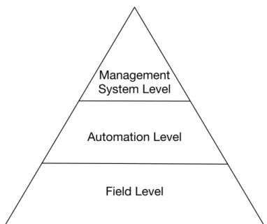
In the past it was quite common for each vendor to have proprietary specifications. However, as BAS and BMS systems became widespread, market competition and request for interoperability lead manufacturers to disclosing their specifications in an attempt to secure a larger market share. This led to the rise of new standards, often as the result of a combination of several vendor proprietary specifications. Currently, the most common communication and management standard used in BMS is the Building Automation and Control Networks (BACnet) [5], Konnex (KNX) [6], Local Operating Network (LonWorks) [7], and Digital Addressable Lighting Interface (DALI) [8]. Each one of them as an important role at different levels of a building management and automation system. As shown in Figure 2.2, those levels are Management System Level, Automation Level and Field Level [9]. The all set of devices, sensors or actuators, compose the field layer. The Automation level is responsible for all the logic and hardware needed to control those devices and the Management Level consists in the control and management of the system and the reactions to events present in the gathered data.
Figure 2.2: Building Automation System hierarchy.
BACnet fits within the Managemet System level, allowing monitoring different automation systems, while KNX, LonWorks and DALI are Automation level protocols [10]. Regarding DALI, it has its own Field level specification, which is a wired solution specific for lighting. KNX and LonWorks allow different Field level protocols, having the first one a wireless solution, KNX RF [11].
2.1.1 BAS solutions
Over the years a large number of companies stepped forward to offer solutions for reducing energy consumption in buildings. Companies like Siemens, which provides three different BAS/BMS systems, Honeywell, and Johnson Controls, which claims to be market leader, offer services, using, most of the times, the formerly addressed open standard protocols.
However, these products have some common drawbacks: most of them are highly costly, which ends up to be a problem for medium to small companies to afford, and also, are not open source and don’t allow for building managers to install and integrate new devices and feature at will.
With the rising of IoT, there has been an increasingly amount of novelty solutions that use high scalable technologies, well known communication standards, such as IP, and use lightweight devices with low power consumption. This concepts can also be applied to BAS/BMS and will be addressed over the next section.
2.2
Internet of Things (IoT)
Internet of Things is a concept that has emerged in recent years. It entails that in addition to the devices we usually connect to the Internet, like smartphones or personal computers, a new diversity of devices will also be connected, forming a vast network of smart objects. Devices like vehicles or normal household appliances will be equipped with sensors and actuators that will be able to gather data, giving people and processing systems the information to take better and more valuable decisions [12]. Also, with controllers and the sensing information, these devices can perform certain tasks without human intervention. There was already a concept, used in telemetry, industrial and automation systems, Machine-to-Machine (M2M), which enabled the exchange of information between machines, in order to perform tasks and actions without human intervention. Although both of the concepts goals remain alike, i.e. enable communication between machines, M2M should be considered as a subset of IoT, as it lacks in the creation of meaning to the information exchanges. IoT is a wide web of not only M2M networks but also, a vast set of applications that enables, as stated in the previous section, automatic decision making and data analytics.
The concept of IoT was first introduced by Kevin Ashton [13] in 1999, where he stated his idea of having computers gathering information from things around us, that humans couldn’t do by themselves, to give a new perspective to people on how to reduce waste, loss and cost. For this author, we needed to give computers the power to gather information with their own means, so they could sense the world for themselves and overcome the limited time, attention and accuracy humans have.
In the recent years, with the technological advances made in electronics, devices became smaller, low powered and more affordable, giving a boost to the integration of this concept in our society. According to [14], the turning point for IoT would be when there were more devices connected to the Internet than people. This point was reached somewhere between 2008 and 2009, and as can be seen in Figure 2.3, this numbers will grow exponentially in the next years and can even reach over a 6 to 1 factor between connected devices and the world population.
Figure 2.3: Estimated growth of connected devices [14].
Nevertheless, the growth of IoT still faces some challenges. As the authors of [15] state, with the growing number of devices being connected to the Internet, Internet Protocol version 6 (IPv6) is going to be crucial to cope with billions of new devices that will require a unique IP address. Nevertheless, IoT remains with no agreements on what standards should be used, which is a problem since it hampers the communication between devices
The IoT concept, according to [14] will be a very important evolution to the Internet, giving the ability to create new applications to improve people’s lives. The sharing of knowledge and wisdom has always been a key factor for human evolution, and now, with IoT and the help of smart devices that sense, collect and share information, we can create new ways to enhance people’s comfort and well-being.
IoT will have an important role in a vast number of sectors, and building automation is an example of that. The IoT’s rapid growth is giving building managers a wide variety of new technology choices. Darcy Otis, director of analytics and fault detection for the building technologies division at Siemens states that IoT will give BAS more information and better tools to perform its core functions [16].
2.2.1 Wireless Sensor Network (WSN)
WSN is a network of distributed devices, sensors and/or actuators, interconnected by a wireless medium. As stated in [17], this network of nodes sense and control the
environment cooperatively, enabling the interaction between persons or computers and the environment around them.
Nowadays WSNs usually include sensors, actuators and gateways. Sensors are devices capable of detecting changes in environmental variables and supply that information to other nodes. These devices can measure variables like luminous intensity, temperature, humidity, pressure, motion and a wide variety of other environmental data. Actuators, in the other hand, are devices that control mechanisms to alter the physical environment state and perform these actions based on input data. For instance, an actuator can be programmed to turn on or off an air conditioner based on a input trigger set off by the temperature in a room. Lastly, gateways are devices connected to sensors and actuators, responsible for orchestrate and interconnect this devices. Gateways can also be programmed to, based on input data gathered by sensors and a set of pre-loaded rules, trigger an actuator to act on some physical environment element, autonomously.
The connection between these three elements form a WSN, which is the primary enabler of solutions such as building automation. Also, WSNs allied with IoT protocols and standards, can truly create smart environments. Over the following sections these IoT protocols will be discussed.
2.2.2 wireless communication protocols
In this section some of the most used communication protocols in IoT are presented. Since IoT devices often require wireless networking capabilities and to be battery-powered, the main focus for this section will be wireless protocols with low power usage.
When talking about wireless communication, the protocol that first comes to mind is IEEE 802.11, better known as Wi-Fi. This wireless standard was introduced in 1997 by the Institute of Electrical and Electronics Engineers (IEEE) [18], and nowadays is used across laptops, phones and other media devices. Although it has an important role for this kind of technological equipment, IEEE 802.11 has never been widely used for communication between IoT devices. The reason for that are WiFi’s power requirements, often making it unsustainable for smart devices to use.
Another important and well known wireless protocol for communications between devices is Bluetooth. This standard was created in 1999 by Bluetooth Special Interest Group (SIG) and in 2016 reached its fifth version [19]. Bluetooth is widely used for connecting smartphones to other bluetooth enabled devices, such as wearables, cars
and others, making it one of the most used close range communication protocol. Both Bluetooth and Wi-Fi standards have polished and mature specifications, making them reliable communication protocols. However these standards are not suited for low capabilities devices since they were not created with restrictions like low power consumption and limited resources in mind. Over the next sections, will be presented a variety of protocols, more suited for this kind of devices.
2.2.2.1 ieee 802.15.4
The IEEE 802.15.4 standard was introduced by IEEE and its intent was to target Low Rate WPANs (LR-WPANs) [20]. This protocol specifies the two lowest layers of the OSI model, represented in Figure 2.4, and it is branded for its simplicity, low data rates and battery saving [21].
Figure 2.4: Open System Interconnection (OSI) model [22].
These characteristics are what make this standard quite significant for IoT. Since IoT sensors and actuators have many battery constrains, using a protocol that has these concepts in mind, make IEEE 802.15.4 a suitable standard for communications within WSNs.
IEEE 802.15.4 is also the baseline for other IoT communication protocols such as ZigBee, which will be covered in a section below.
2.2.2.2 6lowpan
IPv6 over Low-Power Wireless Personal Area Networks (6LoWPAN) is a standard presented by Internet Engineering Task Force (IETF), and its main objective was to implement IPv6 over low power networks, granting the possibility for IoT devices to be reached through the Internet using a unique address. Also this would allow the use of some IPv6 important features such as Quality of Service (QoS), mobility and multicasting.
6LoWPAN uses the previously addressed standard, IEEE 802.15.4, for the two lowest layers of the OSI model, shown in Figure 2.4. Since the network layer protocol was needed to comply with those two lower layers, and the requirements for an IPv6 based protocol didn’t match the constrained IEEE 802.15.4 standard, 6LoWPAN implemented mechanisms to efficiently transport IPv6 packets within small link layer frames [23].
In order to use 6LoWPAN in a IPv6 network, it is only needed a low complexity edge router to route the traffic from IPv6 to 6LoWPAN, as shown in Figure 2.5.
Figure 2.5: Connection between a 6LoWPAN and an IPv6 network [24].
To sum up, with the proliferating market of IoT devices, the use of IPv6 is un-avoidable, and the fact that 6LoWPAN offers a low power and low complexity way of addressing this problem, makes this protocol a viable solution for its use in IoT environments [25].
2.2.2.3 zigbee
ZigBee is a standard introduced by ZigBee Alliance, released to the public in June 2005. ZigBee is built on top of the IEEE 802.15.4 standard, addressed early, and it specifies the its own implementation of upper layers [26]. As shown in Figure 2.6, ZigBee provides on the Application, a ZigBee Cluster Library (ZCL) that maps commands to be used by developers when defining application profiles.
Figure 2.6: ZigBee protocol stack [27].
Although other standards have been emerging on the IoT constrained devices market, ZigBee widely dominates this market as it has been targeting it since the beginning, as a very low power and low latency standard. Although ZigBee is not suitable for long ranges and has low data transfer speeds, a single master node is able to control 254 devices such as light bulbs and light switches [25].
Early this year, ZigBee Alliance unveiled dotdot1, an application layer protocol that
aims to reduce the fragmentation in IoT by offering a common language between all IoT devices on any network. Due to a cooperation between ZigBee Allience and Thread
Group, a company that created Thread2, which is an IPv6 based protocol, that like
ZigBee is based on IEEE 802.15.4, dotdot is set to launch its first certified products later this year.
2.2.2.4 bluetooth low energy
Bluetooth SIG announced, in 2009, Bluetooth 4.0 including Bluetooth Low Energy (BLE) as a way to address the low power constrained devices that emerged with the
rising growth of IoT.
BLE was a radical departure from the Classic Bluetooth and there was no compati-bility between the two. BLE wouldn’t be compatible with most of the widely adopted Bluetooth protocol that most smartphones and tablets used. This fact forced the emerg-ing of two new classes of bluetooth devices: Bluetooth Smart and Bluetooth Smart Ready, as shown in Figure 2.7 [28]. The first one, known as single-mode device, is only capable of communicate using BLE, being used in sensors (presence sensor, temperature
1https://speakdotdot.com/ 2https://threadgroup.org/
sensors, etc.) or other types of battery-operated and low processing accessories. The second, also known as dual-mode Bluetooth, is capable of communicating with both BLE devices and classic Bluetooth devices, being more suitable for smartphones, IoT gateways and other more powerful devices.
Figure 2.7: Product examples of Bluetooth single and dual-mode modules. Adapted from [28].
BLE is suitable to low-energy devices because it adopts a client/server model where devices are in a sleep state and periodically send advertisement messages for clients, such as a smartphone or a gateway, discover it and begin a connection as shown in Figure 2.8. When connected, the clients can ask for data in a pre configured interval [28].
Figure 2.8: BLE discover of devices. Adapted from [28].
More recently, Bluetooth SIG introduced support for IPv6 networking in Bluetooth 4.2 and Bluetooth 5.0 taking advantage of the 6LoWPAN standard.
To sum up, BLE is one of the best solutions for communications between IoT devices due to its low energy consumption and acceptable data transfer rates.
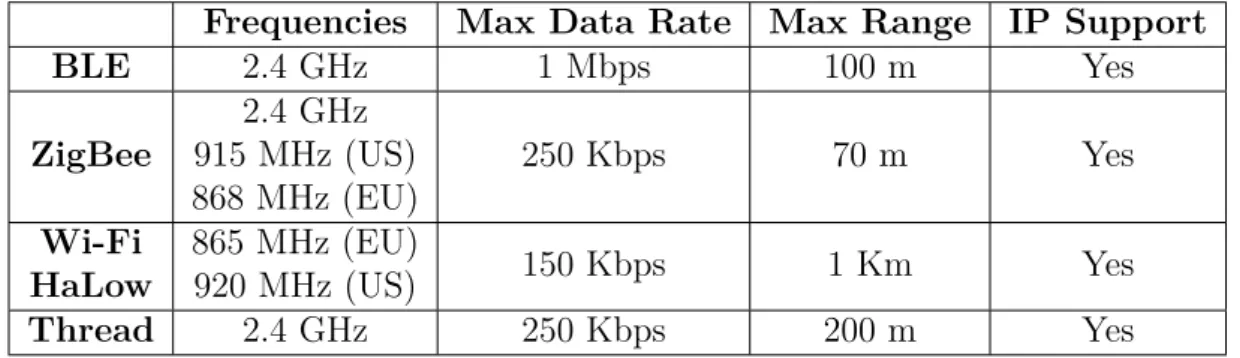
2.2.2.5 wireless communication protocols comparison
In this section is presented a comparison between the addressed wireless commu-nication protocols, adding two more wireless technologies: Wi-Fi HaLow [29] and Thread.
Briefly, IEEE 802.11ah, also known as Wi-Fi HaLow, is a recently published standard that aims to bring Wi-Fi closer to IoT solutions. This is a strong possibility since Wi-Fi HaLow uses a lower band than the classic Wi-Fi, which confer to it nearly twice the range while also granting a more robust connection in any kind of environments [29]. Wi-Fi HaLow is also an energy-efficient protocol that, allied to the benefits of Wi-Fi, such as government-grade security and easy setup, can become an important player in the wireless communication protocols for IoT.
Regarding to Thread standard, as addressed before, is an IPv6 based protocol, that like ZigBee is based on IEEE 802.15.4. Although this protocol was created for smart houses, Thread Group is expanding its connectivity to the buildings sector.
These standards, although not fully or already available, have great potential for future adoption and therefore will also be considered.
Frequencies Max Data Rate Max Range IP Support
BLE 2.4 GHz 1 Mbps 100 m Yes ZigBee 2.4 GHz 915 MHz (US) 868 MHz (EU) 250 Kbps 70 m Yes Wi-Fi HaLow 865 MHz (EU) 920 MHz (US) 150 Kbps 1 Km Yes Thread 2.4 GHz 250 Kbps 200 m Yes
Table 2.1: Wireless Communication Protocols Comparison
Regarding the protocols addressed in the previous sections, BLE and ZigBee, they are both suitable for a building automation solution. However, BLE have higher data rates than ZigBee, while achieving highly efficient power saving. Also, another advantage of BLE over other protocols is its widespread integration in smartphones, tablets and even laptops, with a large share of them already equipped with Bluetooth Smart Ready. This makes it better suitable for some IoT applications such as health care and building automation, where the user’s smartphone can be an integral part of the system, being able to interact with the other devices.
2.2.3 application protocols
As previously stated, the fast growth of IoT devices motivated the search for lightweight protocols in order to enable constrained devices to efficiently communicate with other nodes.
In this section will be presented protocols that address the application layer of the OSI model, shown in Figure 2.4, and are suitable to be used in IoT, are presented. Since IoT solutions address a huge amount of different scenarios, with different requirements, bellow protocols that have different features will be presented, and the strengths and weak points of each will be evaluated.
2.2.3.1 mqtt
Message Queue Telemetry Transport (MQTT) is a M2M communication protocol introduced by IBM in 1999, but was only standardized in 2013 as OASIS [15]. MQTT follows a publish/subscribe client/server model and, due to its simplicity, it is suitable to be used in constrained devices.
The publish/subscribe model features three components: a broker, publishers and subscribers. In the scenario shown on Figure 2.9, the central piece, the server, is a MQTT Broker, and the other components such as data gatherers and data consumers are clients that connect to this broker. Clients are able to publish and/or subscribe to topics on the MQTT broker, and its task is to route messages from publishers, to the corresponding subscribers of each topic [15].
Taking as example the case illustrated in Figure 2.9, a temperature sensor pub-lishes data on some topic and the MQTT broker forwards this messages to the clients subscribed to that temperature topic. MQTT offers the possibility of four different communication topologies: one-to-one, many-to-one, one-to-many, many-to-many [31]. The advantage of this protocol is that publishers do not need to send the same informa-tion to every client nor need to be aware of its presence. This makes the protocol well suited to be used in contexts where devices need to be as efficient as possible, which is the case of IoT environments.
Regarding the guarantees of a successful message delivery, MQTT has three levels of Quality of Service (QoS): at most once (0), at least once (1) or exactly once (2) [32]. The level 0 of QoS, also known as "Fire and Forget" is the most basic one, since the message is sent only one time to the subscribers. It has no fail mechanisms, so if, due to a network error, the message does not reach its target, is not resent by the broker. This level of QoS is suited when occasional unsuccessfully message delivers do not jeopardy system operation or when the broker-clients connection is stable enough. With level 1 of QoS, the sender stores the published message in cache and waits for the acknowledge message. If the acknowledge is not received within a pre-programmed time interval, the message is sent again. The drawback of this level os QoS is that a message can be received multiple times if the acknowledge does not reach the sender. Lastly, QoS level 2 grants that a message is delivered exactly one time, however this process introduces a greater overhead, as it takes longer than any other level of QoS.
Other important features of MQTT are the last will message, where a client can register a message to be delivered to a specific topic in the case of a lost of connection between the broker and the client, and the security concerns, in which an authentication method is provided, using a username and password. Also, regarding security, the payload of the message can be encrypted with SSL/TLS.
To sum, MQTT is an important Application layer protocol and very suitable to be used in constrained networks and devices as a powerful communications standard.
2.2.3.2 coap
Constrained Application Protocol (CoAP) is an application protocol created by IETF with the objective of providing Representational State Transfer (REST) functionalities to constrained devices and networks. REST is a standard used in communications between computer systems on the Internet. Although this principle is a well-known and adopted standard for HTTP, when talking about IoT, whose devices are energy-wise constrained, this standard presents a high overhead [33]. CoAP comes to resolve this
drawback by presenting a lightweight RESTful solution, following a request/response pattern, with the constrained devices market in mind.
As shown in Figure 2.10, CoAP, unlike HTTP, uses User Datagram Protocol (UDP) in the underlying layer of its architecture. This fact makes CoAP communication more efficient as packets are sent without handshaking, or congestion control mechanisms that would introduce more overhead, as used by Transmission Control Protocol (TCP). The communication reliability is implemented by CoAP lightweight internal mechanisms [33].
Figure 2.10: CoAP protocol architecture.
As is also shown in Figure 2.10, CoAP is divided into two sub-layers: re-quest/response and messages. The messages layer is responsible for message processes such as fail and duplication handling, since UDP, as stated before, does not have reliability mechanisms [33]. The request/response layer is responsible for enabling the RESTful interaction by offering well known methods such as GET, POST, PUT and DELETE to interchange data [34].
CoAP has also an "observe" resource that enables clients, through a publish/subscribe mechanism, to observe a resource and when there is a change, the client is notified by the server [34]. All CoAP features make this protocol also very attractive for some use cases in an IoT environment.
2.2.3.3 amqp
Advanced Message Queue Protocol (AMQP) is a communication protocol, initially created aiming at the financial sector, that, like MQTT, runs over TCP and adopts a publish/subscribe architecture. The use of this protocol for financial purposes is due to
the fact that AMQP has powerful mechanisms that grant high reliability and scalability that are crucial for that sector.
AMQP architecture is composed, as shown in Figure 2.11 by three elements: produc-ers, clients and the broker, being the last one divided in two components, the exchange and topic queues. The producers publish messages in a specific topic and the exchange module is responsible for depositing those messages in the correct topic queue. Clients are connected to the queues of specific topics and then have access to the published messages in those queues [33]. This system allows that instead of the broker having to send the same message to multiple clients subscribed to a topic, the message is only sent to the respective queue. Also, it allows clients to be offline at the time the message is sent to the queue, since it is stored there until it is consumed [15].
Figure 2.11: AMQP protocol architecture [35].
Although for majority of IoT environments reliability is not a deciding feature for the communication system, there are some few cases where that is indispensable. For instance, in a situation where a luminance sensor that sends periodic data of the measured values, a lost message will not be a huge problem because shortly after, another value will be sent and the prior loss will have almost no impact to the system. However, in a hospital, if an emergency message in not delivered successfully could mean a life threatening situation for a patient. Situations like this ensure the importance of a communication protocol like AMQP in the IoT context.
2.2.3.4 xmpp
Extensible Messaging and Presence Protocol (XMPP) is, like the former, a standard-ized message-oriented communication protocol and it was created by Jabber open-source community in 1999 for establish near real-time instant messaging (IM), presence infor-mation, and others [35].
XMPP, as shown in Figure 2.12 uses a decentralized architecture where there can be more than one server and the messages can be transferred between them until they reach the desired destination, ensuring that way a high scalability [15].
Figure 2.12: XMPP protocol architecture.
Unlike the protocols addressed previously, XMPP supports not only a pub-lish/subscribe architecture, but also a request/response one. XMPP uses an eXtensible Markup Language (XML)-based approach to messaging, which allows multiple exten-sions of the protocol to be created, making it a highly extensible protocol. However, being that XML-based messages are text based, the communication overhead is higher [33].
Although XMPP was not designed for IoT environments, it still has capacity to be an important protocol in some specific IoT use cases, due to the near real time message exchanging and the high extensibility offered.
2.2.3.5 application protocols comparison
In this section, the protocols previously addressed will be compared and an evaluation of the environments where each one of them is more suitable is provided. Bellow, in Table 2.2, the protocols are compared based on the type of transport used, the presence of security mechanisms and QoS, and also the support of Publish/Subscribe or Request/Response patterns.
Regarding MQTT and AMQP, both protocols use a publish/subscribe pattern but, although AMQP offers a wider variety of features, MQTT gains for being more lightweight, less complex and easier to deploy in most cases, client and broker wise. For this fact, MQTT is usually the choice for most systems, where there are not very restrictive requirements. Nevertheless, both protocols are suited for IoT environments with constrained and low-power devices.
MQTT CoAP AMQP XMPP
Transport TCP UDP TCP TCP
Security SSL and User/Password auth DTLS SSL SSL
QoS Yes Yes Yes No
Publish/Subscribe Yes No Yes Yes
Request/Response No Yes No Yes
Table 2.2: IoT Application Protocols Comparison.
Looking at CoAP, the greater difference between the last two is the use re-quest/response pattern, instead of a publish/subscribe one. Also, CoAP uses a one-to-one transfer protocol between a client and a server, which makes it more suitable as state change model, instead of an event driven one.
Finally, the XMPP although being a near real time communication protocol with an high number of features, such as allowing both publish/subscribe and request/response patterns, still lacks by not being as lightweight as the other protocols. Nevertheless, this protocol has a place in the market for solutions where reliability is a key factor.
2.2.4 IoT enabled BAS solutions
According to the author of [36], the old industry of BASs systems is being disrupted by the Internet of Things. Only some of the most known BAS companies are trying to integrate IoT principles and open protocols in their solutions in order to keep themselves in a leading market position. The emerge of cheap and small devices with wireless connectivity using open standards and the possibility of creating affordable automation environments, using open-source software, are now in reach, providing a wider variety of solutions to empower buildings with automation capabilities and thus, reduce the energy consumption while increasing the comfort in buildings.
A practical example of a building automation system, using IoT principles and standards, is HCL Technologies BAS. HCL Technologies is a member of the Intel Internet of Things Solutions Alliance [37] and uses an Intel-based gateway to deliver a powerful, yet cost-effective building management solution [38]. In this system, as shown in Figure 2.13, is used an Intel’s IoT gateway empowered with HCL BAS software is used, which is responsible for providing a web interface and means for simple automation mechanisms, e.g. turning the Heating Ventilation and Air Conditioning (HVAC) system on when a temperature threshold is reached. The HCL BAS software and gateway supports protocols like ZigBee and Wi-Fi, and the translation between them is made without need of configuration by the building manager.
Figure 2.13: HCL Technologies BAS deployment architecture [38].
Although the presented solution constitutes a robust and novel solution as a BAS, with basic automation that can address most of building manager’s needs, there is a lack of complex automatic correlations between events generated by the sensors network. In the next section the importance of Complex Event Processing (CEP) modules to enhance the performance of event processing as well as the intelligence of a building through complex correlations is presented.
2.3
fault tolerance in component-based systems
Nowadays, most system architectures are composed by individual components (physical or logical) with well-defined communication interfaces. This can bring several advantages such as the reusability or replaceability of components without affecting the overall operation of the system [39].
Nevertheless, this type of architecture has to be tolerant to failures of components(or nodes), in order to achieve an high availability solution, which is a crucial feature to the majority of systems [40]. As the author of [41] suggests, an error is the manifestation of a fault in the system, and a failure is the manifestation of an error on the provided service by the system. The same author also classifies faults on the base of their sources, manifestations and persistence, namely software errors, materials errors or transmission errors. Therefore, a node failure can be caused either by an internal error
on the software, a physical malfunctioning on the component or the shutdown of the communication links to the node.
In order to have a fault tolerant system, fault detection and fault recovery techniques must be implemented. Bellow, some of those techniques are presented.
Fault Detection Techniques
Fault detection is the process of collecting information about the system’s nodes state. This information can be gathered by failure detectors using two different keep alive messages: i) ping; and ii) heartbeat [41]. In the first one the failure detector sends a ping message to the monitored nodes and waits to receive an acknowledge message (ack). If the monitored node is down, due to a failure, the failure detector will not receive the ack and therefore conclude that the node is down. In contrast, for the heartbeat message it is the monitored node that sends a periodic message to the failure detector, informing that it is still running as expected. If the detector does not receive a heartbeat message from a node, after a timeout, it concludes that the node is no longer available.
The author of [41], claims that heartbeat messages have more advantages when compared to ping messages, such as the heartbeat need for half the messages used by ping detectors. However, the ping detectors only have to preform time control in case of a failure in receiving an acknowledge, while the heartbeat detectors need to keep track of the time to detect the absence of heartbeats after a timeout.
Regarding the fault detector’s location in the system, the author of [42] identifies two approaches, a centralized or distributed detector. The centralized approach uses a single node to perform the monitoring of other components, however, although this approach being efficient and accurate to identify faults [42], it constitutes a single-point of failure in the system. Plus, in large-scale systems, the traffic generated by these messages can congest the network, resulting in a more expensive and inefficient solution. The distributed approach uses several nodes as failure detectors, which eliminates the single-point of failure problem, however, introduces more complexity to the system [41].
Fault Recovery Techniques
The fault recovery occurs immediately after a detector senses the fault of a system’s node. According to the author of [43], the high availability of a system is normally achieved using redundant entities, whereby, when a component fails, the redundant node takes over its tasks. The author of [44] states that there are two types of physical redundancy: i) active replication; and ii) primary backup.
Regarding the active replication, it is usually addressed as a N-modular redundancy approach [43], in which a set of replicated modules receive the same input, and the resulting outputs from the different modules are compared and the result with more concordance(majority) is elected as the output. In Figure 2.14 this active replication method is depicted. The most common N-modular redundancy is the Triple Modular Redundancy (TMR). TMR uses a set of three replicated modules, thus, it allows one module to fail, or produce a faulty value, whilst the remainder correctly operating modules are still able to mask that failure.
Figure 2.14: N Modular Redundancy.
Concerning the primary backup approach, also known as hot standby redundancy [43], it uses a primary node, and one or more unused backup nodes. In this approach, there is a need for a failure detector so that when the primary node fails, the backup node can be notified to take over the processing. In Figure 2.15 the hot standby redundancy is represented, and as can be observed, both the active and the passive replicated module need to be connected in order to be synchronized [43].
Figure 2.15: Hot standby redundancy. Adapted from [43].
The author of [43] also states, as an example, a situation with three hosts connected through a common communication bus. Each host need to send periodic heartbeat
messages to this bus and, if a host’s heartbeat is missing, due to a failure in the host or in the network, the other hosts can act immediately to resolve the failure.
The methods presented in this chapter can be used in any component-based system to achieve an acceptable level of fault tolerance, however, each method can be more suitable to different situations.
2.3.1 fault-tolerance in iot
In typical smart environments, sensors and actuators are connected to a gateway, also called a sink, that is capable of communication and processing the received data, either by itself or by sending to another component responsible for doing so [45]. Therefore, three core components of a smart environment that have a direct effect on the whole system operation, can be considered: devices, gateways and automation engines. A device malfunction can only be surpassed by human intervention when it has no self- healing mechanisms. Otherwise there would have to be redundant devices. At the gateway level, since it is a sink device where the information flows to, redundant gateways would also be necessary. Otherwise, in case of multiple gateways connected to different devices, the other gateways should be able to sense that there was a disconnected gateway and takeover the control for the lost devices. Lastly, the automation engines, like the other components, could resolve a failure situation by having redundancy or self-healing techniques implemented in the application. However, in case of irreversible failure, gateways should be able to sense that the automation components are unreachable and, in a perfect scenario, having automation logic implemented so that the system could work at an emergency state until the automation engines are re-established.
2.4
automation logic
Automation can be described as actions preformed without human intervention. In the present dissertation context, automation is achieved using a logic component that receives all events, gathered by sensors from the environment, and infer actions based on buildings manager preloaded rules. For instance, events like movement in a room or temperature and humidity changes, are sent to this automation component that, based on a set of rules, can send triggers to turn on/off lights, HVAC units or others.
In a small house, the number of sensors and events are fairly small and thus, there is no need for a powerful and complex automation unit. However, in a building context,
the amount of events generated is much higher, which requires the use of a more efficient and high performance platform. Also in an environment with so many variables, events cannot be treated isolated from the greater context, so there is a need for a platform that able to correlate these isolated events and infer complex action-reaction relationships. In the next subsection, a system capable of inferring actions based on processing and correlating large event streams is presented.
2.4.1 complex event processing
With the emergence of IoT in different areas, huge amounts of data, that need proper analysis, are produced. However, in areas like smart homes and buildings, the information streams need to be processed almost instantly in order to infer quick actions. CEP is a technology used to process and analyse large streams of data, from multiple sources, and infer real-time conclusions or actions based on the detection of patterns and complex events. As illustrated in Figure 2.16, a complex event is inferred when a certain number of isolated events happen in a specific pattern.
This processing methodology is used in different contexts where a real-time and high performance platform to process data is needed. One of these cases is the financial industry where, in order to take low risk and profitable actions, CEP is used to deduce real-time trading predictions.
Figure 2.16: Detection of complex events using Complex Event Processing. As stated before, smart buildings could also use CEP to greatly increase the quality of its automation. In particular, with a CEP engine, the events generated by the
network of sensors can be analysed to derive actions that, with a classic automation system, would be impossible. As a simple example, in an empty room where the air conditioner is turned off, a sharp decrease of temperature over a small period of time could mean that a window was left open and thus, a message could be sent to the building manager alerting this situation. In this example, with the gathered data from different sensors, such as temperature and presence, over some time, the Complex Event Processing (CEP) engine was able to infer a conclusion. This type of conclusions are only achieved if the automation system takes into consideration multiple events across time instead of analyzing them separately.
A CEP engine implements a set of tools such as filtering, time windowing, aggregation or pattern detection of events, and makes possible to design complex rules using these mechanisms. They can be implemented either by using a query-based model using a query language similar to SQL, or a rule-based model, where a rule is divided in three components: an event, the condition that is evaluated when the event arrives and the action that is taken when the condition is satisfied.
c h a p t e r
3
S m a rt B u i l d i n g S o l u t i o n
In this chapter it is provided a solution to improve efficiency and usability of a building by adopting automation mechanisms which enhance the intelligence of the building. Considering IoT principles, this system should be capable of processing large data streams in real time, analyzing and correlating events, and react and adapt to emergency states and always guarantee a minimum functionality. This solution is intended to integrate the SmartLightinhg project which is addressed in this chapter.
This chapter begins with a brief description, in section 3.1, of SmartLighting project and its intentions of developing a smart environment of automation and control in IT2 building. Later, to ensure that all system needs are addressed and taken into account, in section 3.3 a survey of necessary capabilities and requirements to satisfy stakeholders is done.
Since the main aim of this dissertation is the failure handling and adaptation of the gateways to emergency states, in section 3.4, five critical scenarios of operation are addressed.
Finally, in section 3.2, a presentation and evaluation of the system architecture, and its components’ interactions are discussed.
3.1
smartlighting project
3.1.1 project overview and objectives
The SmartLighting project[46] aims to create a smart environment in IT2 building in order to automate lighting and HVAC infrastructures. IT2 building has been running with Compact Fluorescent (CFL) luminaries, which, are often not only, inefficient and hazardous for the environment, but also, in most cases, unable to support variation of the luminous output, i.e. to be dimmed.
This project intends to remove all these CFL luminaries by Light-Emitting Diode (LED) luminaries, that can resolve all previously stated issues and also be combined with sensors. These can used to collect data from the environment such as luminance, temperature, humidity, motion and others. The collected data is then used to act in real-time to the changes in sensor values.
Such system needs to be backed up by an intelligent management platform in order to react based on a set of rules and input streams of sensor values. Moreover, there will be mechanisms to correlate events and determine patterns that enable a more immediate reaction. As an example, if a user has the habit to turn on the AC every day in the morning, the system will be able to learn and automatically replicate that action as soon as the user arrives in the building.
Also, the system can use external sources like meteorological forecasts to take preventive actions, such as increasing the dimming levels of luminaries and the building temperature in cold rainy days.
Additionally, users should be able to set their own rules to enhance the comfort in their offices. This could be done either by using a mobile application or a web interface. Also, these user platforms can enable use of notifications, providing ways to alert the building occupants of important events. For instance, users can be informed about future meetings, the presence of another occupant in the building, and more.
Finally, an important feature for this project is the failsafe mechanisms to ensure that all basic automation needed for the building’s proper operation. This includes such things as the trigger of a motion sensor to light up corresponding luminaries, which should work even in situations of failure in core elements of the architecture or network communications. This can be achieved by giving gateways, the component that communicates directly with the sensors and actuators, lightweight processing mechanisms to ensure the basic functionalities described before. This will be the main focus of the presented dissertation.
3.1.2 stakeholders
The success of a project depends directly in the people involved, either by developing its features or simply by consuming them in its final form. A correct identification of the stakeholders, their motivations and expectations, plays an important role in the success of any project. In SmartLighting project, 4 stakeholders were identified, namely:
In SmartLighting project, 4 stakeholders were identified, namely: • Building occupants
• Building owners • Building managers • Developers team
The primary stakeholders in this project, are the IT2 building occupants and owners. While occupants will take direct advantage from the implemented features due to the enhanced comfort and usability of the building, owners gains will be economic as far as the building energy consumption and maintenance costs will be reduced.
As for building managers, the benefits come from an easier interaction and configu-ration of the whole system. A more precise aware of system’s components status and a notification system, can help prevent or quickly react to systems failures.
Lastly, the developers team take a huge benefit in the success of the project since they are interested and devoted to create the best product possible that fulfils all the other stakeholders expectations.
3.1.3 use cases
Based on the stakeholders’ survey done in the previous section, the two main actors for this BAS solution are the building’s manager and the occupants. Those actors directly use the platforms and resources provided, to enhance the comfort of the environment around them as they please, so the main focus for user driven cases will be in those two.
Although there are many use cases for both the building’s manager and the occupants, in this section will only be addressed those that were already implemented in this project, giving a greater understanding of the overall project’s functionalities. Later, in section 3.4, the use cases and scenarios introduced by this dissertation work are presented.
The building occupants will be the principal users to interact with the system. This interaction can be achieved by using either a mobile application or a web interface. The use cases addressed bellow combine the most common and frequent operations:
Figure 3.1: Use case diagram of building occupants interaction with the system. • Login/Logout: This use case is intended to enable the access to user oriented
features. The building occupants can login to the platform, either using the mobile application or the web interface, to access preferences and personal environment control features.
• Request changes in devices state: The building occupant can request a change in the state of a device, that can be accepted or denied by the system depending on the access rights of the user. For instance, an occupant can request a change in nearby devices like air conditioners, lights, and others.
• List nearby devices: This use case allows users to request the list of nearby devices, based on its location, allowing to access or request changes to devices in the same room as the occupant, giving that these are the most likely to be needed access.
• Configure device preferences: The user can create or edit device pre-sets, allowing the selected values to be applied automatically to the device in future uses. For instance, the air conditioner in a user office can be pre-set to 21ºC so that when this device is turned on, that value is automatically set. These changes would also be checked against the user access rights.
• Configure user rules: This use case allows building occupants to create rules that perform a set of actions automatically, giving the right conditions. For instance, the user could create a rule to automatically turn the air conditioner on if the temperature in his office exceed a giving value.
Building manager
Figure 3.2: Use case diagram of building manager interaction with the system. • Manage building structure: The manager can create the representation of
the building in the structure management platform. This allows the creation of a virtual portrait of the floors, rooms and areas of the building.
• Distribute devices: This use case permits connected devices to be distributed through the areas and rooms of the building’s virtual representation.
• Configure global rules: The building manager has the ability to add, delete, enable or disable rules for the whole building. These core rules’ main purpose are the increase in building´s efficiency. For instance, instead of leaving the corridors lights always on, a rule can be created to turn them off when there’s no one walking by. There is also a mechanism to test the rule before the deployment.
3.2
system architecture
Taking into account the objectives for this dissertation, and the existing architecture for the SmartLighting project, the proposed architecture has in mind, not only IoT and complex event processing principles, but also the referred features for this dissertation such as failure handling and rules distribution through gateways.
In this section, the global system architecture for this project, represented in Figure 3.3, is presented alongside with a description of all the components that compose the solution.
Note that components like the CEP engine, and the Building Manager (BM) are already implemented in a past dissertation of the SmartLighting project [2].
Figure 3.3: Smart Building: Architecture diagram
3.2.1 components overview
User Management
The user management platform is responsible for giving to common users of the building, the ability to interact with the platform through a web page. Users can manage their own building rules and control field devices directly. This can be done by publishing on the broker the desired changes, or by communication directly with the CEP Engine or the building management platform.
Building Management
The building management component is a user friendly platform that aims to facilitate the rule management and the configuration of the building’s schema. The building manager can create, edit or delete rules in a simple intuitive way and this component later translates them in a complex language that the CEP Engine can understand. Also, through a virtual representation of the building, the BM can
distribute devices across all its areas. After the correct configuration of the desired devices, this component is responsible for providing the information of how should the CEP engine, and the other blocks of the architecture, address to this device in order to send an order to change state or report new sensor data to the CEP Engine.
CEP Engine
The CEP Engine is a crucial component in the proposed building automation solution. This engine must be a real-time and high-performance component, able to process hundreds of sensor triggered events, per second, based on complex rules created by users. The actions performed by this engine can either be directed to an actuator or to a component in the platform. For instance, sending a notification to the building manager when there are irregular sensor readings.
Broker
The broker component, which refers to a message broker, is responsible for receiving and routing information across the connected components. Every component connects to receive and send information, to and from other components.
Gateway Manager
The gateway manager is the component responsible for rules distribution to gateways and fail handling. The first one, since gateways will be equipped with the ability to process events, in the case of a failure in the CEP Engine, there is the need for a regulator to distribute and be always aware where the gateways’ rules are being deployed. In case of a gateway failure, it is also responsible for distributing the devices and rules from that gateway, to other ones capable of supporting them. Also, the gateway manager should guarantee a balanced number of rules and devices across all gateways. For instance, if two gateways are in the reach of the same device, the gateway manager should allocate that device to the one with fewer devices.
Gateways
Gateways are responsible for discovering devices and communicating with them. These nodes have to convert sensor events into understandable messages to the au-tomation engine, and vice versa. Also, gateways should be equipped with a lightweight automation engine so that, in case of a failure in the CEP engine, or in the broker, the gateways can continue to process events, and thus, a minimum downtime in the system’s operation.
![Figure 2.1: Building Automation System schematic. Adapted from [4].](https://thumb-eu.123doks.com/thumbv2/123dok_br/15874346.1088456/26.892.276.706.129.459/figure-building-automation-schematic-adapted.webp)
![Figure 2.3: Estimated growth of connected devices [14].](https://thumb-eu.123doks.com/thumbv2/123dok_br/15874346.1088456/29.892.163.752.135.485/figure-estimated-growth-of-connected-devices.webp)
![Figure 2.6: ZigBee protocol stack [27].](https://thumb-eu.123doks.com/thumbv2/123dok_br/15874346.1088456/33.892.228.687.127.379/figure-zigbee-protocol-stack.webp)
![Figure 2.7: Product examples of Bluetooth single and dual-mode modules. Adapted from [28].](https://thumb-eu.123doks.com/thumbv2/123dok_br/15874346.1088456/34.892.152.722.264.432/figure-product-examples-bluetooth-single-dual-modules-adapted.webp)
![Figure 2.11: AMQP protocol architecture [35].](https://thumb-eu.123doks.com/thumbv2/123dok_br/15874346.1088456/39.892.231.688.459.707/figure-amqp-protocol-architecture.webp)
![Figure 2.13: HCL Technologies BAS deployment architecture [38].](https://thumb-eu.123doks.com/thumbv2/123dok_br/15874346.1088456/42.892.149.728.146.471/figure-hcl-technologies-bas-deployment-architecture.webp)


