DOI: http://dx.doi.org/10.1590/1980-5373-MR-2016-0012
Materials Research. 2016; 19(5): 1176-1179 © 2016
Residual Stress Evaluation by X-Ray Difraction and Hole-Drilling in an API 5L X70 Steel
Pipe Bent by Hot Induction
Rodrigo Braga Cegliasa, Juciane Maria Alvesa, Ramón Alves Botelhoa, Eustáquio de Souza Baeta
Júniora, Igor Cuzzuol dos Santosa, Nicki Robbers Darciano Cajueiro de Moraesa, Rebeca Vieira de
Oliveiraa, Saulo Brinco Diniza, Luiz Paulo Brandaoa*
Received: January 7, 2016; Revised: July 21, 2016; Accepted: August 11, 2016
The API 5L X70 steel is used in high-pressure gas transmission pipelines. Because of this, knowledge of presence of residual stress and their magnitude is important to assess the material integrity in service. For the pipeline manufacturing, tubes need to be curved which is often made using the hot induction
bending process. This process can introduce diferent residual stress depending of tube position. For
this research, in order to evaluate the residual stress, was used an API 5L X70 tube that was previously curved by hot induction process. Samples were taken from the extrados, intrados, neutral line and straight section of the curved tube. Residual stresses were studied by two conventional methods: X-Ray
Difraction (XRD) and Hole-Drilling, which are destructive and non-destructive methods, respectively,
in order to assess their qualitative responses. Each of these methods presents particular methodologies
in sample preparation and material analysis, but also they difer in factors such time consumption and cost of the analysis. The qualitative responses obtained by the two diferent methods were comparable
and satisfactory and pointed out the existence of a compressive residual stress state in steel pipe.
Keywords: API 5L X70, X-ray difraction, hole-drilling, compressive residual stress
* e-mail: [email protected]
1. Introduction
High-strength low-alloy (HSLA) steels are widely found
in the oil industry due to their high mechanical strength and
toughness. The American Petroleum Institute (API) regulates
the pipelines for these applications, such as the API 5L X70 steel pipe. The process of manufacturing the pipes is called UOE because it involves folding the rolled sheet into the “U” shape, cylindrical pressing “O” and expanding the pipe diameter to the limits set by the API 5L standard “E”1.
During manufacture, the material goes through several deformations, welds and phase transformations that can lead to residual stresses. Residual stresses are those that remain in the material even when all external forces are
withdrawn. They have elastic behavior and their inluence on
the material performance depends on their kind, magnitude and distribution in the crystal lattice2. A thermal treatment
may be performed to relieve stresses harmful to material performance3.
The UOE tubes are connected in order to produce a pipeline. For the pipeline construction is necessary bending the tube in order to follow the project instructions. They are often curved via the hot induction bending process. This is one thermomechanical process because it inputs simultaneously, in a narrow ring of the tube, the induction heating and its mechanical bending. Immediately after bending, this tube
ring is water cooling or quenching. After the quenching, the material surface should be in compression and its interior in tension as reported by Barker and Sutton4. Therefore, this hot
induction bending process can introduce phase transformation
and diferent residual stress level depending of tube position.
In general, the presence of compressive residual stress
is considered beneicial for the material since it increases its
fatigue resistance and stress corrosion cracking resistance, for example, and beyond these, compressive residual stresses are subtracted from the applied tensile stresses.
There are several techniques for measuring residual stress, among them the methods of X-ray diffraction and hole-drilling. Since the technique of hole-drilling is destructive and expensive, this work aims to compare it to
the X-ray difraction technique, which is non-destructive
and simpler to use.
2. Experimental
2.1 Material
Samples of a steel tube of API 5L of grade X70, manufactured by the UOE process, welded by submerged
arc process (SAW) and bent by hot induction process,
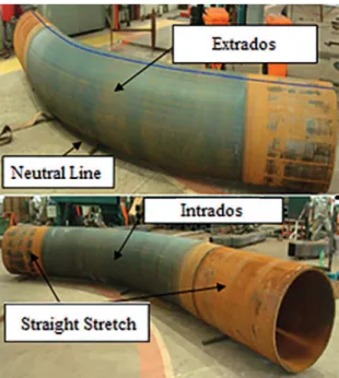
were taken from following positions of the curved tube:
extrados (EC), intrados (IC), straight section (SS) and aSeção de Engenharia Mecânica e de Materiais, Instituto Militar de Engenharia – IME, Praça General
1177 Residual Stress Evaluation by X-Ray Difraction and Hole-Drilling in an API 5L X70 Steel Pipe Bent by Hot Induction
neutral line (NL) (Figure 1). The values of yield strength
and tensile strength informed by the manufacturer were equal to 604 MPa and 746 MPa, respectively. The chemical composition of the material under study is shown in Table 1.
at any point near the surface can be calculated on the basis of angles phi (φ) and psi (ψ), from the rotation and tilt of the
sample goniometer of the X-ray difractometer.
Correlating the variation of interplanar distance (d) of
sample with diferent angles of inclination (ψ) can calculate the residual stress (σφ) in any direction from its surface considering the diferent rotation angles of sample (φ) in texture goniometer
as Equation 16,7. For this, should also be informed the elasticity
modulus (E) of the material and its Poisson’s ratio (ν).
Table 1: Chemical composition of API 5L X70 (wt%).
C S Al Si P Ti V Cr
0.076 <0.025 0.034 0.312 <0.025 0.018 0.045 0.277
Mn Nb Ni Mo B N Cu Fe
1.63 0.055 0.018 0.0022 0.0005 <0.01 0.0048 Balance
2.2. Methods
2.2.1. X-Ray Difraction
Evaluation of residual stress by X-ray diffraction is based on measuring the change of interplanar spacing of crystal lattice. A crystalline material free of residual stresses shows no change in its natural interplanar spacing. In opposite, the presence of residual stress on crystal lattice causes variations in interplanar distances due to deformation in lattice. Therefore, if the material has your crystalline structure under a stress tensile state, the interplanar spacing perpendicular to this tension state will increase while those parallel to this will decrease5.
Depending on residual stress distribution presented in microstructure there will be a shifting or a broadening of its diffraction peak when compared to the residual stress free material. That is, the macro and microstresses are responsible for these behaviors, respectively5.
Due to the low penetration of X-rays, a few microns, we consider the plane stress state, i.e., σ3, to be zero. Delection
X-ray difraction samples with dimensions 58 x 58 x 4.5
mm were ground and polished with 1 and 3 µm alumina.
The specimens used in this work were irstly cut from the 5L
X70 steel tube using blowpipe. From these material pieces, samples were removed for the XRD analysis using up bandsaw.
Measurements were performed in a PANalytical X’PERT PRO MPD difractometer with CoKα, radiation with 45 kV and 40
mA voltage and current, respectively. Data were taken with psi
(ψ) geometry8 at a relatively high 2θangle of 123.751°, since
the larger the angle, the greater the sensitivity to stress. Stress
software of PANalytical was used for processing the results.
2.2.2 Hole-Drilling
The hole-drilling method, standardized by ASTM E837:01, consists of making a small blind hole in the material and measuring the deformation near its edge using extensometers. In the calculation of residual stresses, it is considered that the strain caused in the hole-drilling combined the tensions
(P, Q and T)9 who are they, biaxial stress, shear stress 45°
and other shear stress in plane, respectively (Equation 2).
The triaxial strain gage rosettes used for the test were type PA-06-062RE-120 model with Strain Factor 2.04, target
diameter of the bore of 1.59 mm (1/16”) and mean diameter bars of 5.13 mm (0.202”).
3. Results and Discussion
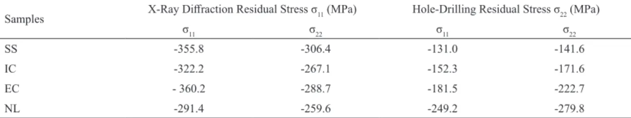
The residual stress results obtained by the X-ray difraction method and hole-drilling (Table 2) whose experimental errors were between 2.9 and 3.4%, and 5.3 and 11.9%, respectively,
show the presence of a compressive stress state in all samples.
Figure 1: Places from which samples were taken from the tube.
(
1)
s
i
n
d
d
d
ν
E
1
1
0 0
2
σ
}
=
-
+
φ
}
P
Q
T
(
2)
, maxmin
2 2
!
Ceglias et al.
1178 Materials Research
Table 2: Residual stress analyzed by X-ray difraction and hole-drilling.
Samples X-Ray Difraction Residual Stress σ11 (MPa) Hole-Drilling Residual Stress σ22 (MPa)
σ11 σ22 σ11 σ22
SS -355.8 -306.4 -131.0 -141.6
IC -322.2 -267.1 -152.3 -171.6
EC - 360.2 -288.7 -181.5 -222.7
NL -291.4 -259.6 -249.2 -279.8
Figure 3: Residual stress σ22 measured by XRD and Hole-Drilling.
Comparison of the results of residual stress (σ11 and σ22)
measured by X-ray difraction and by hole-drilling is made
in Figures 2 and 3.
Table 2 presents the σ11 and σ22 values measured by the
two methods: X-ray difraction and hole-drilling. Observing
this table, one can see that both presented similar tendency, showing that the results in modulus obtained via hole-drilling
were, in general, smaller than the ones got by X-ray difraction. This can be assigned to the speciicities of each method, as it will be discussed ahead. Only the σ22 for the neutral line
(NL) exhibited slightly discrepant behavior.
The graphs in Figures 2 and 3 present a comparison
between the residual stresses σ11 and σ22, respectively,
obtained by XRD and hole-drilling. In these Figures, can also
be observed that the curves obtained for σ11 and σ22 showed
the trend pointed previously, but it became evident that σ22
was always smaller than σ11 for all measured positions on
the tube, for the two assessment methods used.
The UOE process used for the tube manufacturing involves some steps that can be summed up in cold forming in “O” form of the steel plate followed by longitudinal welding in order to seal it. Both cold forming and welding processes introduce high level of residual stresses as can be seen in the obtained results
for straight section (SS), which was not bended. Observing once
more the Figures 2 and 3 can be emphasized, that the residual
stress for the (SS) sample was in highest level. Thus, it can be
inferred that the induction bending process did not introduce any additional residual stress in the bended tube.
The residual stresses observed for neutral line (NL) and for straight section (SS) show the same tendency but diferent
levels when assessed by the two methods. For both methods
used, the residual stress in (NL) was smaller than in (SS).
The neutral line is the region that should not undergo plastic deformation during the bending process, but it is also subject to residual stresses resulting from the heating and cooling inherent in the bending process by induction.
One can also highlight that independent of the measurement
method, the residual stress in the (EC) position is higher than in the (IC). This can be related to the kind of plastic
deformation that took place during tube bending. This process introduces in the concave region a compressive stress state larger than that in the convex region.
The results showed that both techniques were able to identify a compressive stress state distributed in the analyzed material what is compatible with the hot induction bending process and the quenching encompassed in this method as explained in the introduction of this article1,4. The diference
between the values obtained by the techniques may be due to two reasons. First, during the introduction of the hole in the sample, a new state of tension adjacent to the periphery thereof is developed, which may result in an inaccurate result of residual stress. Second, the X-ray beam has a penetration of about 10 μm10 (0.01 mm) near the surface of the material
,
which depends on type of anode used, sample absorption
coeicient, the X-ray beam tilt and the lit area10,11 and the
drill used in the hole-drilling method achieves an average depth of 0.5 mm12. Therefore, these techniques should not
be compared directly from the quantitative point of view due to intrinsic factors involved in measuring residual stress, but they presented qualitatively comparable responses.
1179 Residual Stress Evaluation by X-Ray Difraction and Hole-Drilling in an API 5L X70 Steel Pipe Bent by Hot Induction
The largest compressive stress module observed was 360 MPa. This value is lower than the yield stress of the material, whose value is about 604 MPa. Residual stresses are self-balanced and their distribution in the microstructure does not occur uniformly.
Some authors13,14 have indicated that the compressive
stress state is favorable to the mechanical behavior of materials due to the fact that it raises fracture toughness and increase resistance to fatigue crack propagation and stress corrosion cracking. Due to this, this type of residual stress
is beneicial to the crystal structure.
4. Conclusions
In face of the results obtained in this study, it can be conclude that both techniques used in this research, X-ray diffraction and hole-drilling, identified with successful the residual stress state distribution in the API 5L X70
steel pipe curved via hot induction process. However, the
quantitative results showed some differences, which can be understood due to factors inherent in the evaluation methods. Each technique must be selected from its peculiarities, which involves the method of preparation and analysis of the material and subsequent analysis of measurement data.
The measured stress state in entire tube was compressive, and results obtained by both methods were qualitatively comparable. This is consistent with the facts that after the quenching, the material surface should be in compression, and its interior in tension as mentioned in the article introduction, and also because both assessment methods used , X-ray and hole-drilling, evaluated the residual stress near the surface of the material. The observed compressive stress state is considered beneficial and suitable for pipeline application.
It can be also concluded that the induction bending process did not introduce any additional residual stress in the bended tube.
5. Acknowledgements
The authors thank Protubo and CSN for supplying the material and CAPES for inancial support.
6. References
1. American Petroleum Institute. Speciication for Line Pipe: API
Speciication 5L. American Petroleum Institute: Washington;
2012. 192 p.
2. Lu J. Handbook of Measurement of Residual Stresses. 2nd ed. Bethel: Society for Experimental Mechanic; 2005. 417 p.
3. Jun TS, Korsunsky AM. Evaluation of residual stresses and strains using the Eigenstrain Reconstruction Method. International
Journal of Solids and Structures. 2010;47(13):1678-1686. 4. Barker RS, Sutton JG. Stress Relieving and Stress Control. In: van
Horn KR, ed. Aluminum Vol. III: Fabrication and Finishing. Metals Park: American Society for Metals; 1967. p. 355-382.
5. Prevéy PS. X-ray difraction residual stress techniques. In: ASM
Handbook, 10 – Materials Characterization. Metals Park: American Society for Metals; 1986. p. 380-392.
6. Guimarães LR. Estudo de parâmetros experimentais envolvidos
na determinação de macrotensões residuais, em tubos de aço inoxidável, pelo método da difração de raios-x [Dissertação].
São Paulo: Instituto de Pesquisas Energéticas e Nucleares; 1990.
7. Fitzpatrick ME, Fry AT, Holdway P, Kandil FA, Shackleton
J, Suominen L. Measurement Good Practice Guide No. 52:
Determination of Residual Stresses by X-ray Difraction.
Teddington: National Physical Laboratory; 2005. 77 p.
8. Dias JS, Chuvas TC, Fonseca MPC.Evaluation of Residual Stresses
and Mechanical Properties of IF Steel Welded Joints by Laser
and Plasma Processes. Materials Research. 2016;19(3):721-727.
9. ASTM International. ASTM E837-01e1: Standard Test Method
for Determining Residual Stresses by the Hole-Drilling Strain-Gage Method. West Conshohocken: ASTM International; 2001. 10. Talonen J, Aspegren P, Hänninen H. Comparison of diferent methods
for measuring strain induced α-martensite content in austenitic
steels. Materials Science and Technology. 2004;20(12)1506-1512.
11. Cullity BD. Elements of X-Ray Difraction. 2nd ed. London:
Addison-Wesley Publishing Company; 1978. 555 p. 12. Rocha AS, Nunes RM, Hirsch TK. Comparação entre difração de
raios X e “método do furo cego” para medição de tensões residuais em barras cilíndricas. Revista Matéria. 2009;14(3)965-976.
13. Acevedo C, Nussbaumer A. Efect of tensile residual stresses on
fatigue crack growth and S-N curves in tubular joints loaded in compression. International Journal of Fatigue. 2012;36(1):171-180.
14. Rossini NS, Dassisti M, Benyounis KY, Olabi AG. Methods of