Faculty of Engineering of the University of Porto
Informatics and Computing Engineering Master Program
Development of a Visual GUI Modelling Front-End
MIEIC 2008 – Master Thesis
by
Rodrigo Manuel Lopes de Matos Moreira
Supervised by
Assistant Professor Ana Cristina Ramada Paiva Pimenta
April 2008, Porto – Portugal
Abstract
Nowadays, most of software systems usually feature graphical user interfaces (GUIs). They are a means to provide functionalities to the users whenever they interact with them. GUIs' appearance, correctness and usability qualities contribute to the users’ decision of using such software systems. However, GUI testing is difficult, extremely heavy, and with a limited set of both tools and techniques to assist in the testing process.
Methods and test practices based on formal specifications, or formal models, might help to systematise and automate GUI testing to higher levels, due to their potential to generate test cases automatically. Nevertheless, existing GUI testing approaches feature some limitations (problems) that are seen as obstacles in the promotion to their adoption in industrial environments: the time and effort required for building GUI formal models; modellers and testers are reluctant to write formal textual specifications/models; and there is the need to define coverage criteria best adapted for GUI testing, such as, coverage of navigation maps (the behaviour related to the possible paths an user can walk through in order to open/close the several windows of a GUI application).
This dissertation addresses some of the above problems. In order to overcome such problems, this research work started with an analysis on the state of the art towards GUI modelling. This task became highly profitable since it guided to innovative ideas that led to the design of a new visual notation for GUI modelling. Such visual notation aims to hide, as much as possible, the formal details inherent to models typically used in model‐based testing (MBT) approaches and promote the use of MBT in industrial environments providing a visual front‐end for modelling which is more attractive to testers/modellers than textual notation.
A set of rules was defined in order to automatically translate visual GUI models to a textual object‐oriented model‐based formal specification language (Spec#). GUI models developed with the visual notation are then translated automatically to Spec# that can be then completed manually with additional behaviour which was not included in the visual model for being developed in a higher level of abstraction. This translation is performed by means of a software tool (developed during the course of this work), that aims to maintain consistency between the visual model and the textual formal (Spec#) model. Once Spec# model is completed, it can be used as input to Spec Explorer (model‐based testing tool) which generates test cases and executes those tests automatically.
The approach proposed in this research work is illustrated and validated by a case study performed on the Notepad application that ships with the Microsoft Windows operating system. Overall, the visual notation together with the automatic translations mechanism provided savings in the time spent with the modelling activity around 40% when compared with the GUI modelling directly in Spec#.
A scientific paper was submitted to an international conference as a way to reveal the approach proposed, the outcomes produced and results achieved by this research work.
Acknowledgements
I would like to express my gratitude to my Supervisor for all the assistance and support I've received for this dissertation. I would like to thank for all the guidance, invaluable help, intellectual rigor and exchange of ideas. The encouragement and guidance of Assistant Professor Ana Cristina Ramada Paiva Pimenta proved invaluable throughout the process.
I express a deep appreciation to my parents who provided me items of greatest worth: responsibility, respectability and integrity. Thank you for standing by me through the many trials and decisions of my educational career. I express a deep appreciation for their efforts to help me get where I am today.
Contents
INTRODUCTION ... 6
1.1 Scope ... 7 1.2 Problem ... 8 1.3 Goals ... 8 1.4 Outcomes ... 9 1.5 Dissertation Outline ... 9GUI MODELLING ... 11
2.1 UML Extensions for GUI Modelling ... 11 2.1.1 The UML Profile for GUI Layout ... 12 2.1.2 UMLi ... 15 2.1.3 Wisdom Profile ... 19 2.2 usiXML ... 22 2.3 Canonical Abstract Prototypes ... 27 2.4 ConcurTaskTrees ... 29 2.5 Spec# ... 34 2.6 Discussion ... 35VAN4GUIM OVERVIEW ... 37
3.1 VAN4GUIM UML Profiles ... 37 3.1.1 Containers ... 38 3.1.2 User Actions ... 39 3.1.3 Hybrids ... 42 3.1.4 CTT Connectors ... 44 3.1.5 Window Manager ... 46 3.2 Overall testing process ... 48 3.3 Structure of the GUI model ... 49 3.4 Coverage criteria over the visual GUI model ... 503.5 VAN4GUIM to Spec# Translation Rules ... 50 3.6 Model‐based testing with Spec Explorer ... 52
CASE STUDY ... 55
4.1 Notepad ... 55 4.2 VAN4GUIM Notepad Specification ... 55 4.3 Spec# Model Obtained ... 62 4.4 Metrics ... 65CONCLUSIONS AND FUTURE WORK ... 67
REFERENCES ... 68
APPENDIX A ... 69
APPENDIX B ... 77
Chapter 1
Introduction
A noteworthy branch of the businesses all over the world depend upon the software industry for product development, production, marketing, support and services. That's why the importance of improving software quality becomes more evident. By conducting software tests in order to check its correctness and completeness during its development and before the release of the products, it is possible to increase the confidence in the software quality. Nowadays, the complexity and size of the software is growing and manual testing is becoming impractical. Software testing has evolved throughout years leading to improvements on overall testing techniques, such as, test cases construction, test automation, among others.
Nowadays, most of these software systems often rely on graphical user interfaces (GUIs) instead of offering textual menus and built‐in typed commands. GUIs embody an important role on the acceptance of a software system to its end‐users. They correspond to the front‐end of the system, making them the intermediary between the user and the back‐end. Its correctness, graphical power, ease of use and appropriateness settle on whether system users will eventually make use of the software.
GUI testing is an area of increasing importance, where the tests are performed from the end users point of view. Software companies have the best of interests on finding defects on their products before their costumers’ do, not only to meet user demands and therefore increase confidence in relation to their software, but also to induce correctness and commitment with them. For these reasons, GUI testing is extremely necessary. It is particularly time consuming, labour‐intensive, expensive and difficult. Presently used GUI testing methods are almost ad hoc and require test engineers to manually develop the necessary scripting to perform test execution, and though evaluate if the GUI is effectively tested. However, there are some tools that can help improving GUI testing process. Some of these tools exploit a broadly accepted method that generates GUI test scripts which relies on the capture/playback technique. Such technique requires testers to perform labour‐intensive interaction with the GUI via mouse events and keystrokes. During interaction user events are recorded into scripts which and can be automatically played later for GUI testing. However, when different inputs are required to conduct the test or even if the GUI changes, it is then required to re‐generate the test scripts. In addition, it is hard to cover all possible test cases for all GUI components and capture/playback method often records redundant data [1].
The use of a model to describe the behaviour of a system is an established and key advantage regarding testing. Models can be used in numerous ways, for instance, to improve quality of software documentation, code generation and test case generation. Model‐based testing represents the automation of the design of black‐box tests. The usage of a model to describe the behaviour of a GUI in combination with an automated test tool to generate test
cases, execute those tests and report errors found, can dramatically reduce the time required meant for testing software.
Recently, model‐based testing has been receiving attention due to the potential to automate test generation and increasing model driven software engineering practices. Nevertheless, the usage of uncommon and unfeasible modelling notations, the lack of integrated tool environments and support, the difficulties inherent to the constructions of models, the test case explosion problem, the gap between the model and the implementation, remain as obstacles regarding the adoption of model‐based GUI testing approaches. In addition, the models used are often textual models and usually testers and modellers prefer working with visual/graphical notations.
1.1 Scope
The establishment of UML as a standard for object‐oriented design has contributed for increasing confidence towards modelling. GUI modelling represents the process required to create a representation of a GUI in a higher level of abstraction, by defining its behaviour, as well as relationships and restrictions among its components. Models can be constructed using several types of notations, ranging from informal to formal specification languages. Depending on the situation in hands, it is necessary to choose the notation that suits the best of interests. The richness of modelling techniques in software design and the impact of modelling on software testing, has guided to the definition of a set of testing practices, known as Model‐ Based Testing (MBT).
Figure 1 – Simplified view of the generic model‐based GUI testing process
Figure 1 illustrates the activities and artefacts involved in the generic model‐based GUI testing process, which embraces the following steps [2]:
1. Construction of the model – the model‐based testing process starts with the construction of the model of the application under test (AUT). The model captures the requirements of the AUT [3].
2. Test case generation and coverage analyses – the model is then used as input to generate test cases according to given coverage criteria.
3. Model to implementation mapping – the model can normally be translated by means of a tool, to interactively relate the abstract user actions defined in the model with actions on physical GUI objects in the application under test, generating code automatically.
4. Test case execution − test cases are executed over the AUT and the results obtained and states reached are compared with the expected results and expected states described in the model.
1.2 Problem
One of the several activities that testers must perform during a model‐based testing process is build models. Most of the times, these models are textual and require deep knowledge of the formalism details which may involve hard work making modelling an intensive task. Much often, testers do not have the acceptance and even patience to build such models.
UML is a graphical notation widely used in industry. However, their limitations for constructing GUI models are known [4] and their inconsistencies [5] are a drawback when trying to use UML on a model‐based testing process.
Nowadays, software applications are becoming bigger, therefore more complex with composite GUIs, making manual testing of such GUIs a much more difficult activity than before. In addition, when a GUI is modified, the tester needs to start the process from the beginning, redefining the test suite and executing the tests over again. With MBT it is possible to automate more of the testing process. If the GUI model changes, test cases are automatically calculated and executed.
Another problem regarding GUI testing the difficult task of choosing the appropriate coverage criteria to test different features of the GUI, such as, navigation map (describes how the navigation ‐ opening and closing of windows – of the system happens) and other abstraction levels such as windows dialogs’ behaviour.
1.3 Goals
The main goal of the research work described in this dissertation is to overcome some of the problems with GUI testing some of which were identified in the previous section:
• Develop a visual modelling front‐end, hiding as much as possible, the formal details from both modellers and testers. These visual models will be comprised by
a set of diagrams to describe, at a high level of abstraction, the structure and behaviour of GUIs. The notation should look familiar to modellers and testers, and should be supported, as much as possible, by existing editors. The graphical notation is planned to hide formalism details from testers, diminishing the modelling effort required for GUI modelling;
• Delineate a set of rules to translate the graphical notation into a textual object‐ oriented formal specification language, such as Spec# [6];
• Develop a tool to support the translation process and maintain consistency between the visual model (a set of diagrams) and the textual formal model. Diagrams should be treated as views over the formal model. The formal model may have additional details that are not present in any of the visual diagrams. Expressions shown in selected elements of the diagrams should be written in the underlying formal notation (Spec#).
1.4 Outcomes
The current dissertation expects the following outcomes to be accomplished: • A new modern visual abstract notation comprised by a set of UML profiles and a set of internal rules, with which consistent models may be constructed if following such rules (VAN4GUIM);• A set of rules to translate the visual abstract notation into Spec#;
• A software tool supporting the translation mechanism between the visual notation and Spec# (XMI2Spec#); • A scientific paper with the purpose to describe the approach proposed in this dissertation and the results achieved.
1.5 Dissertation Outline
This dissertation is organized in five main chapters. Chapter 1 gives an introduction regarding overall GUI testing and a further presentation over model‐based GUI testing. It also gives an insight over the scope of this dissertation, describing the model‐based GUI testing process. The problems concerning GUI testing and the activities that testers must perform during a model‐based testing process are indentified. In addition, it describes the goals that have been defined to overcome the acknowledged problems, and also provides an overview of the outcomes that are expected to be realized. Chapter 2 presents several GUI modelling
the UML Profiles of the newly created notation ‐ Visual Abstract Notation for GUI modelling (VAN4GUIM). In addition, it explains the proposed model‐based testing process as well as the structure of the GUI model that is created whenever using VAN4GUIM. Topics such as coverage criteria over the visual model, the VAN4GUIM translation rules to Spec# and model‐ based testing with Spec Explorer are also covered in this chapter. Chapter 4 features the achieved results of a case study in order to evaluate and validate the proposed approach. Finally, Chapter 5 presents the achievements of this dissertation and discusses future expansion issues for it.
Chapter 2
GUI Modelling
The concepts of visually modelling software, as well as the tools to support this activity, have been around for a few years. Modelling represents the practice of creating abstractions of a system to maintain as a concept or a set of concepts flow. When applied to software, the world modelling naturally leads to UML diagrams. By making use of software modelling one is capable to: develop, communicate and discuss software models; assure that the system under specification is being correctly built; iteratively develop software, where the models and other higher abstraction levels facilitate rapidly changes or updates. There are at least, three kinds of models that are worth noting: models that track software development process; models to automate software generation and models for MBT.
Most of GUI models used are not adequate for MBT. MBT requires description of both behaviour and structure of the GUI under test. Pre and post formal notations, such as VDM++ [7] and Z [8], are good at representing the state but they are not indicated to represent the behaviour. It is possible however, to extend such notations in order to overcome such boundaries.
GUI modelling addresses quite a few challenges such as, the description of windows behaviour, use case scenarios and navigation maps. Modelling the behaviour of a window induces an eminent setback, the state explosion problem [3]. Scenarios are used to structure the GUI model in different levels of abstraction with the purpose to model user interactions. Modelling the behaviour of a GUI represents the notable challenge in GUI Modelling.
A more detailed study was performed over several GUI modelling approaches. As such, the current chapter presents and discusses these approaches.
2.1 UML Extensions for GUI Modelling
Currently, GUIs play an important role in most of software systems, as they represent
the fore‐front of the system. UML is a natural candidate for GUI modelling since it represents a standard notation for object‐oriented modelling of applications. GUIs can be decomposed in two main groups: a dynamic or behaviour group and a static or layout group [9]. While the dynamic group can be modelled using existing UML diagrams and elements, GUI layout cannot, due to the fact that all existing UML diagrams are not layout‐aware. In addition, it is not clear and simple to identify how UI elements, such as user tasks and display, are supported by UML. So, it is necessary to make use of UML extension mechanisms, like constraints, tagged values, and stereotypes, in order to provide more flexibility to the existing UML notation. With these extension mechanisms it becomes possible to construct several UML profiles particularly suited for GUI modelling.
UML profiles represent a clear‐cut mechanism for adapting an existing meta‐model
with constructs that are specific to a particular domain, platform, or method. Furthermore, they can be used to create additional constraints to an existing meta‐model. Stereotypes are one of the most important elements of UML 2.0 profiles. A stereotype extends a class of the meta‐model by adding additional semantics and offers the possibility of modifying its syntax. The notation of stereotypes can be changed by defining icons in order to provide an intuitive meaning. This step becomes useful as it eases the task of matching designers’ draft to models.
Constraints are used to define the semantics of the stereotype and correspond to Boolean
expressions [10].
2.1.1 The UML Profile for GUI Layout
Several researchers have recognized the lack of support for GUI’s layout information in
UML and thus have followed different approaches. Kai Blankenhorn and Wilhelm Walter [9] have developed an UML Profile for GUI Layout, which is a UML 2.0 profile that uses Diagram
Interchange to store layout information while staying fully conform to standards. The diagram‐
interchange specification originates XMI from the XML metadata interchange format, which is used for storing information about the elements of a UML diagram. Although it serves quite well this purpose, it fails to express the graphical layout information of the diagram. Diagram Interchange, as an integral part of UML 2.0, adds drawing and layout information to every UML element, including size and position. This additional information enables new applications for UML that could not be handled properly with previous versions of the language. They claim their profile is one of the first to explore these new possibilities. The profile’s meta‐model makes use of stereotyped classes that are linked by constrained associations, taking benefit from UML 2.0 extension mechanisms.
The meta‐model of the UML profile for GUI Layout can be seen in Figure 2.1. The main
concept of the profile is a base element called ScreenArea, which is a stereotyped class representing the rectangular area of the screen. The base element is comprised by two subclasses, FunctionalScreenArea and ContainerScreenArea. The first is used to present a fraction of functionality to the user, for instance, images, texts, links and forms. Finally, the
ContainerScreenArea acts as a container of other ScreenAreas. Other elements worth notice
are StaticUIFunctionalities – an element responsible to present a visual element on the screen ‐ and ActivatableUIFunctionalities, which performs an action if clicked.
In order to improve the usefulness of the graphical language and to transfer the general look of designer sketches to models, creators have developed a set of stereotype icons, as illustrated in Figure 2.2. The right column displays the original screen elements, as extracted from designers’ sketches.
Figure 2.1 – Meta‐model of the UML profile for GUI Layout
Figure 2.2 – Stereotype Icons
The diagram below (Figure 2.3) represents a rough layout of a web page. It contains the mentioned ScreenAreas, which dictate the functionality of the modelled web page. Three of the ScreenAreas are given names and are denoted as being abstract by having their name written in italic. A particular interest is that since Abstract ScreenAreas (Figure 2.1) cannot be instantiated, and therefore cannot be directly displayed on screen, they may however have
concrete specialized ScreenAreas, which can be displayed instead.
Figure 2.3 – A rough layout of a web page
It is possible to create and use a template for multiple pages that share the same layout, by specializing ScreenAreas. As stated, the rough layout displayed above can be used as a template, taking benefit of ScreenArea sub‐classing and specialization, as can be seen in Figure 2.4.
Figure 2.4 ‐ ScreenArea sub‐classing and specialization
2.1.2 UMLi
The Unified Modelling Language (UML) has been broadly accepted by software
developers, but not so much by UI designers. In addition, there are no modelling languages and tools capable to support round‐trip between developers and designers. In addition, UML lacks support for modelling certain aspects of GUIs [11]. To overcome this problem, a new notation was born to diminish the gap between developers and UI designers. The UMLi notation aims to be a light‐weight extension to the UML notation with the purpose to provide greater support for UI design. This approach was proposed by [12], and is a result of a research held at the University of Manchester.
UMLi notation has been influenced by model‐based user interface development
environment (MB‐UIDE) technology. In fact, MB‐UIDEs provide a context within which declarative models can be constructed and related as part of the user interface design process. In addition, the authors of UMLi believe that the MB‐UIDE technology offers many insights into the abstract description of user interfaces that can be adapted for use with the UML technology, such as techniques for specifying static and dynamic aspects of user interfaces using declarative models.
With UMLi, it is possible to model both structure and behaviour of a system. The notation defines three distinct types of models: presentation model, domain model and
behaviour model. The presentation model represents the visual part of the user interfaces
that can be modelled using object diagrams composed of interaction objects. Domain models specify classes and objects that represent the system entities, the domain elements. Behaviour models describe object collaboration and common interaction behaviour, such as tasks, actions and events.
Regarding domain models it is typical and indicated the usage of class diagrams. Concerning the presentation model, the interaction objects mentioned before, are also called
widgets or visual components. The tasks of selecting and grouping such objects are crucial for
modelling UI presentations. It is found hard to perform these tasks because of the amount of interaction objects with different functionalities. Regarding UML, these tasks are not doable because UML does not provide graphical distinction between domain and interactional objects. However, using the UMLi user interface diagram notation it became possible to overcome such complicated tasks.
A set of stereotypes were defined in order to specify the UMLi user interface diagram
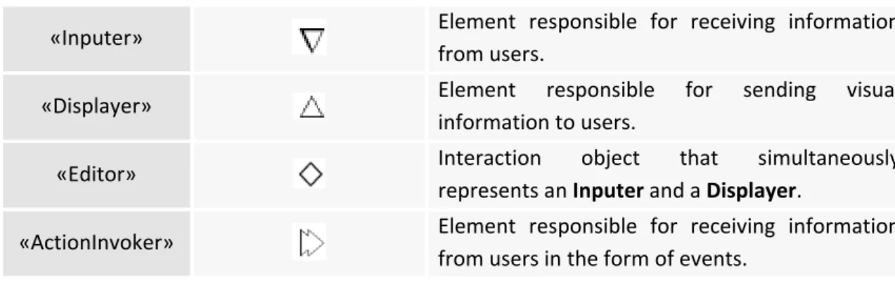
notation. The user interface diagram is composed of six constructors that specify the role of each interaction object in a UI presentation and are defined in Table 2.1.
Stereotype Icon Description
«Free Container»
Element that represents a top‐level interaction object that cannot be contained by any other interaction object.
«Container»
«Inputer» Element responsible for receiving information from users.
«Displayer» Element responsible for sending visual
information to users.
«Editor» Interaction object that simultaneously
represents an Inputer and a Displayer.
«ActionInvoker» Element responsible for receiving information
from users in the form of events. Table 2.1 – UMLi user interface diagram’ stereotypes
To model the behaviour of collaborative objects, activity diagrams come into place. Due to the ability to describe object collaboration and common interaction behaviour, UMLi activity diagrams provide a greater support for UI design than regular UML activity diagrams, by the usage of UML extension mechanisms.
Modelling transitions are useful for selection states. A combination of transitions, forks and joins is adequate for activities that can be executed in parallel. A combination of transitions and branches is suitable for modelling the situation when only one among many activities is executed. However, for the designing of interactive applications there are situations where these constructors can be held to be rather low‐level, leading to complex models. The following behaviours are common interactive application behaviours, but usually result in complex models. 1. Order independent behaviour is presented in Figure 2.5. Figure 2.5 – Order independent behaviour Activities A and B are called selectable activities since they can be activated in either order on demand by users who are interacting with the application. Thus, every selectable activity should be executed once during the performance of an order independent behaviour. Further, users are responsible for selecting the execution order of selectable activities. An order independent behaviour should be composed of one or more selectable activities. An object with the execution history of each selectable activity (in point 1 above) is required for achieving such behaviour.
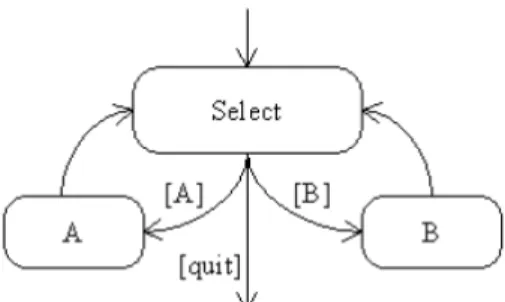
Figure 2.6 – Optional behaviour Users can execute any selectable activity any number of times, including none. In this case, users should explicitly specify when they are finishing the Select activity. Like the order independent behaviour, the optional behaviour should be composed of one or more selectable activities. 3. The repeatable behaviour is presented in Figure 2.7. Figure 2.7 – Repeatable behaviour Unlike the order independent and optional behaviours, a repeatable behaviour should
have only one associated activity. A is the associated activity of the repeatable behaviour. Further, a specific number of times that the associated activity can be executed should be specified. In the case of the diagram in Figure 2.8 (c), this number is identified by the value of X.
Figure 2.8 – The UMLi modelling of an order independent selection state in (a), an optional
selection state in (b), and a repeatable selection state in (c).
Order independent and repeatable behaviours are common in interactive systems [12], UMLi proposes a simplified notation for them. The notation used for modelling an order independent behaviour is presented in Figure 2.8 (a). There we can see an order independent selector, rendered as a circle overlying a plus signal, , connected to the activities A and B by return transitions, rendered as solid lines with a single arrow at the selection state end and a double arrow at the selectable activity end. The order independent selector identifies an order independent selection state. The double arrow ended on return transitions identifies the selectable activities of the selection state. The distinction between the selection state and its selectable activities is required when selection states are also selectable activities. Furthermore, a return transition is equivalent to a pair of statechart transitions, one single transition connecting the selection state to the selectable activity, and one non‐guarded transition connecting the selectable activity to the selection state, as previously modelled in Figure 2.8 (a). In fact, the order independent selection state notation can be considered as a macro‐notation for the behaviour described in Figure 2.8 (a). The notations for modelling optional and repeatable behaviours are similar, in terms of structure, to the order independent selection state. The main difference between the notations of selection states is the set of symbols used by their selectors. The optional selector, which identifies an optional selection state, is rendered as a circle overlaying a minus signal. The repeatable selector which identifies a repeatable selection state is rendered as a circle overlaying a times signal. The repeatable selector additionally requires a REP constraint, as shown in Figure (c), used for specifying the number of times that the associated activity should be repeated. The value X in this REP constraint is the X parameter in Figure 2.8 (c). The notations presented in Figures 2.8(b) and (c) can be considered as macro‐notations for the notation modelling the behaviours presented in Figures 2.8 (b) and (c) [12].
2.1.3 Wisdom Profile
The Wisdom Profile is proposed by Nunes and Cunha [13], for the documentation, specification and design of interactive systems. They propose a minimal set of extensions for a UML profile for interactive systems development taking advantages on human‐computer interaction domain knowledge under the notation and semantics of the UML. The extension was named Wisdom UML Profile due to the fact that it was originally created with the purpose to maintain the Wisdom (Whitewater Interactive System Development with Object Models) software development method. Not only the authors believe that, despite the lack of support for building complex interactive systems, UML is the most universally used modelling language, but also that Wisdom extensions are broadly applicable in different process contexts.
The Wisdom approach suggests two important models: the analysis model and the
interaction model. The latter includes the information, dialogue and presentation dimensions,
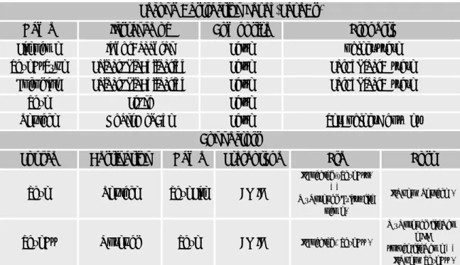
mapping the conceptual architectural models for interactive systems, while maintaining the desired separation of concerns. The analysis model encompasses the UML profile architecture and shared information. During the design phase, the interaction model embraces two other models: the dialogue model and the presentation model. The former specifies the dialogue structure of the application, using an UML based approach of the ConcurTaskTrees (CTT) notation. One of the most important features of the CTT notation is the capability to express temporal relationships between tasks. Accordingly, the creators of the Wisdom Profile took advantage of the UML constraint extension mechanism to express such relationships between tasks. The result of the adaption of the CTT temporal relationships can be seen in Table 2.2. Furthermore, the dialogue model requires an additional definition of stereotypes, constraints and tagged values. As such, authors define the «Refine Task» stereotype, which is an association between two tasks, denoting that the target class (subtask) specifies the source task (parent task) at a lower level of detail. The task association is unidirectional and can only be used between task classes. As for the Refine task association it implies a set of constraints, namely: • {xor} – represents an UML constraint to be applied to a set of associations. It indicates that over the set, exactly one is manifest for each associated instance; • {sequence} – symbolizes a constraint with the purpose to be applied to a set of «refine task». It specifies that over that particular set, associated instances become active in sequential order, i.e., one associated instance activates the other when it becomes inactive; • {deactive} – this constraint is applied to two «refine task» associations, specifying that one associated instance explicitly deactivates the other, when it becomes active. In order to perform task allocation the following tagged values are applied to the task classes: • {abstract task} – tasks that require complex activities and whose performance cannot be univocally allocated;
• {user task} – represents all the tasks performed by the used that do not imply any interaction with the system; • {application task} – tasks completely executed by the application; • {interaction task} – tasks performed by the user interaction with the system. Temporal Relationships Description Independent concurrency (T1|||T2) – denotes that actions belonging to two tasks (T1 and T2) can be performed in any order without any specific constraint; Choice (T1[]T2) – denotes that it is possible to choose form a set of tasks and once the choice has been made the chosen task can be performed, while other tasks are not available; Concurrency with Information Exchange (T1|[]|T2) – same has independent concurrency but the tasks have to synchronize in order to exchange information; Iteration (T*) – denotes the task (T) is performed repeatedly until the task is deactivated by another task;
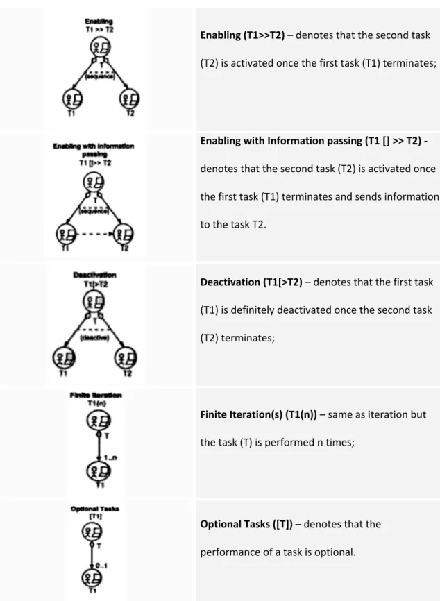
Enabling (T1>>T2) – denotes that the second task (T2) is activated once the first task (T1) terminates; Enabling with Information passing (T1 [] >> T2) ‐ denotes that the second task (T2) is activated once the first task (T1) terminates and sends information to the task T2. Deactivation (T1[>T2) – denotes that the first task (T1) is definitely deactivated once the second task (T2) terminates; Finite Iteration(s) (T1(n)) – same as iteration but the task (T) is performed n times; Optional Tasks ([T]) – denotes that the performance of a task is optional.
Table 2.2 – UML adaptation of ConcurTaskTrees. The circles with the person icon and computer represent a stereotype «task». Furthermore, all the associations between «task» classes are stereotyped «refine task» associations. Finally {xor}, {sequence} and {deactivate} are UML constraints [13].
As to the design model, it defines the physical realization of the interactive system, centring on the structure of the different presentation entities in order to realize the physical interaction
with the user. Like dialogue model, the authors propose a set of UML extensions to support the design model. They have defined the following stereotypes:
• «Interaction Space» ‐ stereotype responsible for receiving and presenting information to the users supporting their task. Typically, interaction spaces are organized in hierarchies and containment relationships can occur between interaction spaces;
• «Navigate» ‐ represents an association stereotype between two interaction space classes indicating the move of a user from one interaction space to another. The navigate association can be unidirectional or bidirectional. The latter means that there is an implied come back in the navigation. Users navigate in interaction spaces while performing complex tasks and a change between interaction spaces generally requires a switch of thinking from the user;
• «Contains» ‐ is an association stereotype between two interaction space classes and representing that the source class (container) contains the target class (content). The «contains» association can only be used between interaction space classes and is unidirectional. • «input element» ‐ is an attribute stereotype denoting information received from the user, typically information that the user can operate with; • «output element» ‐ is an attribute stereotype denoting information presented to the user. For instance, information that the user can recognize but cannot manipulate; • «action» ‐ is an operation stereotype indicating something that a user can perform in the physical user interface that will cause a significant change in the internal state of the system, i.e., changes in the long term information of the system (entities), request for signification functionality, changes in context of the user interface, and others.
2.2 usiXML
User Interface Extensible Markup Language (usiXML) represents a paradigm which
allows designers to develop user interfaces, based on the User Interface Description Language (UIDL). Hence, it becomes possible to specify a user interface at and from different levels of abstraction while maintaining the mappings between these levels, whenever required. In addition, the development phase can start from any level of abstraction, where the final user interface may be composed of several contexts of use at other levels of abstraction. The usiXML model has been developed in the context of the Cameleon research project being held by Jean Vanderdonckt [14].
A considerable number of User Interface Description Languages (UIDL) subsists to attend to different characteristics of user interfaces. However, despite the fact UDLI addresses aspects such as portability, device independency and user‐centred design, it induces a broadcast of several dialects that are not both largely used and do not support interoperability between tools that were developed in the order of UIDL. Furthermore, some UIDLs lack support to attend both traditional GUIs and Multimodal User Interfaces (MUI) needs. As
response, a new notation called usiXML emerged to overcome the above problems. This notation is based on five main concepts: expressiveness of UI, central storage of models,
transformational approach, multiple development paths, and flexible development approaches. The expressiveness of UI remarks that any UI is expressed depending on the
context of use due to a suite of models analyzable and editable by software. As for the central
storage of models key, it denotes each model is stored in a model repository where all UI
models are expressed according to the same UIDL. Regarding the transformational approach concept, each stored model in the model repository may be subject to one or many transformations supporting various development keys. The multiple development paths refer to the development steps that can be combined together to form development paths that are compatible with the organization’s constraints, conventions, and context of use. Finally, the
flexible development approaches point to top‐down, bottom‐up, wide‐spreading approaches. They are supported by flexibly following alternate development paths and enable designers to freely change between these paths depending on the modifications imposed by context of use. UsiXML is a language designed to support multi‐directional UI development. MDUI is based on a framework – Cameleon Reference Framework [15] – that defines UI development steps for multi‐context interactive applications. This framework is illustrated in Figure 2.9. The CR framework structures development processes for two contexts of use into four development steps: Final UI (FUI), Concrete UI (CUI), Abstract UI (AUI), and Task & Concepts
(T&C). FUI represents the operational UI, any UI running on a particular platform. Regarding CUI, it concretizes an abstract UI for a given context of use into Concrete Interaction Objects
(CIOs), in order to define widgets layout and interface navigation. In addition, it converts a FUI into a UI definition independently of the computing platform. Although a CUI makes explicit the final Look & Feel of a FUI, it is still a mock‐up that runs only within a particular environment. AUI defines interaction spaces by grouping subtasks according to various criteria, a navigation scheme between the interaction spaces and selects Abstract Interaction Objects (AIOs) for each concept so that they are independent of any context of use. An AUI abstracts a CUI into a UI definition that is independent of any modality of interaction. Finally,
T&C describes the various tasks to be carried out and the domain‐oriented concepts as they
are required by these tasks to be performed. These objects are considered as instances of classes representing the concepts manipulated.
The framework defines three basic transformation types: Reification, Abstraction, and
Translation. MDUI development refers to a UI tool that enables a designer to start a
development activity from any entry point of the framework, and to a support in the performance of the basic transformation types and combinations from Figure 2.9. Hence, in order to perform such development, the authors gathered two crucial requirements:
a) A language that enables both expression and manipulation of the model at each development steps and for each context of use.
b) A mechanism to express design knowledge that would provide a substantial support to the designer in the realization of transformations.
Figure 2.9 – Cameleon Reference Framework
As a response for the requirements above, usiXML is introduced and defined, and a set of graphical transformation techniques is introduced and defined, respectively.
Since usiXML comprises visual, formal and seamless features, graphical transformation
techniques were chosen to formalize the language. The latter feature refers to the capability offered by usiXML in representing manipulated artefacts and rules within a single formalism. Consequently, this formalism applies equally to all levels of abstraction.
The authors propose that each level of Figure 2.9 could be decomposed into two sub‐levels:
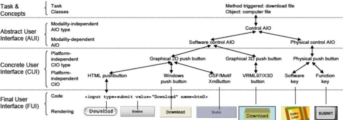
• At the FUI level, the rendering materializes how a particular UI coded in one language (markup, programming or declarative) is rendered depending on the UI toolkit, the window manager and the presentation manager. For example, a push button programmed in HTML at the code sub‐level can be rendered differently, here on MacOS X and Java Swing. Therefore, the code sub‐level is materialized onto the rendering sub‐level.
• Since the CUI level is assumed to abstract the FUI independently of any computing platform, this level can be further decomposed into two sub‐levels: platform‐ independent CIO and CIO type. For example, a HTML push‐button belongs to the type “Graphical 2D push button”. Other members of this category include a Windows push button and XmButton, the OSF/Motif counterpart.
• Since the AUI level is assumed to abstract the CUI independently of any modality of interaction, this level can be further decomposed into two sub‐levels: modality‐ independent AIO and AIO type. For example, a software control (whether in 2D or in 3D) and a physical control (e.g., a physical button on a control panel or a function key) both belong to the category of control AIO.
• At the T&C level, a task of a certain type (here, download a file) is specified which naturally leads to AIO for controlling the downloading.
Figure 2.10 – Example of transformations in usiXML Thanks to these four abstraction levels, it is possible to establish mappings between instances and objects found at the different levels and to develop transformations that find abstractions or reifications or combinations. In addition, the usiXML language provides tool support at the various levels identified in Figure 2.10.
In order to face express multi‐directional development of UIs, usiXML features a collection of basic UI models, such as domain model, task model, AUI model, CUI model, context model and mapping model (Figure 2.11) and a transformation model (Figure 2.12) [14].
Figure 2.12 – usiXML model collection
Beyond the AUI and CUI models that reflect the AUI and CUI levels, the other UI models are defined as follows [14]:
• taskModel: is a model describing the interactive task as viewed by the end user interacting with the system. A task model represents a decomposition of tasks into sub‐tasks linked with task relationships. Therefore, the decomposition relationship is the privileged relationship to express this hierarchy, while temporal relationships express the temporal constraints between sub‐tasks of a same parent task.
• domainModel: is a description of the classes of objects manipulated by a user while interacting with a system.
• mappingModel: is a model containing a series of related mappings between models or elements of models. A mapping model serves to gather a set of inter‐ model relationships that are semantically related. • contextModel: is a model describing the three aspects of a context of use in which an end user is carrying out an interactive task with a specific computing platform in a given surrounding environment. Consequently, a context model consists of a user model, a platform model, and an environment model.
• uiModel: is the topmost super class containing common features shared by all component models of a UI. A uiModel may consist of a list of component model without any order and any number, such as task model, a domain model, an abstract UI model, a concrete UI model, mapping model, and context model. A UI model does not need to include one of each model component. Moreover, there may be more than one of a particular kind of model component.
2.3 Canonical Abstract Prototypes
The concept of abstract user interface prototypes offer designers a form of
representation for specification and exploration of visual and interaction design ideas that is intermediate between abstract task models and realistic or representational prototypes. They represent an intermediate form that can speed the user interface design process and improve the quality of the results. As abstractions, they can serve as an intermediate bridge between task models and realistic designs, smoothing, simplifying, and systematizing the design process.
Abstract prototyping is specified by using content models. A content model represents
the contents of a user interface, without regard for the details of what the user interface looks like and how it behaves. In a content model, a user interface is a collection of materials, tools and working spaces. They are all described in the terms of their purposes or how they are intended to be used. Furthermore, content models help to simplify what a user interface must contain and how its contents are assembled before entering into a deep detail. The abstraction levels that materials, tools and workspaces imply, offer a great and simple support to describe a lot more than a simple common user interface.
Canonical Abstract Prototypes (CAP) are an extension to usage‐centred design that provides a formal vocabulary for expressing visual and interaction designs without concern for details of appearance and behaviour. CAPs embody a model specifically created to support a smooth progression from abstraction toward realization in user interface design. The necessity inherent for their development arose from a growing awareness among practitioners of usage‐ centred design regarding the substantial conceptual gap between the task models needed to drive an effective design and the detailed, realistic prototypes needed for successful implementation. Simple content inventories had proved both too abstract and too imprecise for resolving design issues in very complex user interfaces. A sample regarding Canonical Abstract Prototypes is illustrated in Figure 2.13. Each CAP component has a specific abstract interactive function, for instance, create information or provide a notification. These functions are represented by simple symbols. Canonical Abstract Components model not only the interactive functions to be provided by a user interface, but also the position, size, layout, and composition of the user interface features. The notation, indeed the entire scheme for Canonical Abstract Prototypes, was devised so as to promote precise and consistent modelling while maximizing the utility for practicing visual and interaction designers working on real‐ world projects.
The use of a standard set of abstract components serves a number of purposes. Easy
selection from a palette of available components can speed and simplify the process of abstract prototyping. The standard form facilitates comparisons of designs and makes it easier both to recognize and to describe recurring patterns or common configurations. In addition, because the abstract components are related by their specific interactive function to particular realizations, Canonical Abstract Prototypes provide direct guidance for the visual and interaction design of the user interface. Abstract Prototypes were devised for designing user
interfaces in order to support design decision making at a higher level of abstraction than typical paper prototypes.
Figure 2.13 ‐ Example of a Canonical Abstract Prototype displaying concepts of key notational elements.
Each Canonical Abstract Component is comprised by a symbolic graphical identifier and a descriptive name. The graphical symbols have as purpose to serve as learned shorthand for the various functions available. The notation is quite simple, since it is built on two basic symbols: a generic tool or action and a generic material or container. Materials are the containers, content, information or data. Tools are the actions, operators, mechanisms, or controls that can be used to create, manipulate, transform or operate upon materials. The symbolic notation is built from two glyphs: a square to represent a container and an arrow to represent an action. The combination of a container and an action form a generic hybrid component. Figure 2.14 illustrates the symbols for Canonical Abstract Components.
Fig. 2.14 – Basic symbols for Canonical Abstract Components where (a) represents a generic abstract tool, (b) represents a generic abstract material and (c) figures a generic abstract material.
The generic container can be used as the abstract representation of any type of material, the generic action can represent any sort of tool, and the generic hybrid can represent any component with characteristics of both.
The original set of abstract components and their symbolic representation has suffered
from several improvements through the years. At the moment, the notation comprises a collection of 21 components, which includes 3 generic components, 11 specialized abstract tools, 3 specialized abstract containers, and 7 abstract hybrids. The figure bellow details the complete set of Canonical Abstract Components. It first illustrates the canonical abstract tools, then the canonical abstract materials and, finally the abstract hybrids.
Fig. 2.15 ‐ Canonical Abstract Components featuring (in order of appearance): abstract tools, abstract materials and abstract hybrids. Notice that the first element of each group with a ‘*’ placed there are called generic elements, and the rest are elements of the specialization group.
2.4 ConcurTaskTrees
Task models play an important role in human‐computer interaction field as they represent the intersection between user interface design and other engineering approaches. Further, they provide designers with a means of representing and manipulating a formal abstraction of activities that should be performed to reach user goals. A goal is either a desired modification of state or an inquiry to obtain information on the current state and can be associated with multiple tasks, where there can be different tasks to fulfil the same goal. Despite the fact that task models have always been well thought‐out, only recently user interface designers and developers have realized their importance and the need for engineering approaches to task models to better obtain effective and consistent solutions.
There are many proposals for representing task models. Such notations vary from GOMS (Goals, Operators, Methods, and Selection rules) [16], UAN [17], CTT [18], MAD [19] and GTA [19]. A set of dimensions must be taken into account, in order to better choose the most appropriate notation. Such dimensions are syntax, set of operators for task composition and
level of formality. Syntax means that the notation can be either graphical or textual. For
instance, GOMS are mainly textual, as opposite to ConcurTaskTrees that are graphical. Graphical representations aim to better highlight the hierarchical structure. The set of operators for task composition is a point that distinguishes the proposed notations. It intends to identify the best notation that provides the richest set of temporal operators, in order to provide more flexible ways to perform tasks. The comparison can be seen in Table 2.4. Finally, the level of formality represents the point of abstraction importance to define the meaning of operators.
The ConcurTaskTrees is one of the most widely used notations for task modelling, specifically tailored for user interface model‐based design [20]. This notation has been developed taking into account the previous experience in task modelling and adding new features to better obtain an easy‐to‐use powerful notation, to describe the dialogue in interactive systems. In fact, CTT provides the concept of hierarchical structure, exposing a wide range of granularity allowing large and small structures to be reused and, enables reusable task structures to be defined at both low and high semantic level. CTT introduces a rich set of graphical temporal operators, providing more possibilities than those offered by concurrent notations. These operators can be seen in Table 2.5.
As mentioned, in a model‐based GUI testing approach, task models can be used to define the behaviour of user interfaces. They correspond to the logic of the user interactive layer of the system, and they describe assumptions about how the user will interact with it. In fact, using this approach, CTT grants a considerable number of advantages: they focus on
activities, thus allowing testers to centre on the activities that users perform; its set of temporal operators provides richness and intuitive guidance to clearly express user actions;
and, the notation itself is becoming quite popular
Operators
Notation
GOMS UAN CTT MAD GTA
Sequence X X X X X Order Independence X X X Interruption X X X Concurrency Only CPM‐ GOMS X X X X Optional X X Iteration X X X X Allocation X X Objects X X Performance X X X Pre‐post condition X X X X Table 2.4 – Comparison of operators among notations from task modelling
The integration of CTT into UML can be achieved by using UML extension mechanisms
to represent elements and operators of the CTT notation. However, another approach consists of extending the UML meta‐model, thus introducing a separate task model, and establishing relationships between the CTT elements and existing UML elements, becoming possible to represent CTT operators as UML connectors. Further, [20] have proposed a different approach that enables the integration of CTT in the UML through the extensions of UML 2.0 activity diagrams.
The first approach represents CTT as stereotyped class diagrams. Constraints
associated with UML class, association and dependency stereotypes are defined to enforce the structural correctness of the CTT models. The major drawbacks of this approach are the low expressiveness of the notation and the lack of semantic validation of the CTT temporal constraints in terms of UML class diagrams. The second approach is outlined in [21] and covers the definition of an UML extension for Interactive Systems. It describes the integration points between UML models and task models in a complementary way. Yet, a unified integration at semantic and notational levels should be provided towards an effective incorporation of task models into UML.
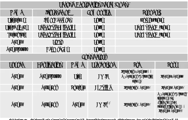
The larger the complexity of the GUI, the more difficult the modelling task will be. Thus, tools such as CTTE [22] offer the possibility of modelling such systems, aiming to help end users in this complicated task. Hier archy Tasks at same level represent different options or different tasks at the same abstraction level that have to be performed. Read levels as “In order to do T1, I need to do T2 and T3”, or “In order to do T1, I need to do T2 or T3”. Enabling Specifies second task cannot begin until first task performed. Example: I cannot enrol at university before I have chosen which courses to take. Choice Specifies two tasks enabled, then once one has started the other one is no longer enabled. Example: When accessing a web site it is possible either to browse it or to access some detailed information.
Enabling w/ in fo change Specifies second task cannot be performed until first task is performed, and that information produced in first task is used as input for the second one. Example: The system generates results only after that the user specifies a query and the results will depend on the query specified. Concurr e n t tasks Tasks can be performed in any order, or at same time, including the possibility of starting a task before the other one has been completed. Example: In order to check the load of a set of courses, I need to consider what terms they fall in and to consider how much work each course represents. Concurr e n t co mmunicati ng tasks Tasks that can exchange information while performed concurrently Example: An application where the system displays a calendar where it is highlighted the data that is entered in the meantime by the user. Task ind e pe nd e n ce Tasks can be performed in any order, but when one starts then it has to finish before the other one can start. Example: When people install new software they can start by either registering or implementing the installation but if they start one task they have to finish it before moving to the other one.