Design of a modular submersible platform for monitoring marine
ecosystem (Benthic Lander)
Hugo João Miranda Alves
Dissertação de Mestrado
Orientador na FEUP: Professor Doutor Mário Augusto Pires Vaz Orientador no INEGI: Engenheiro Tiago António Nunes da Silva Morais
Mestrado Integrado em Engenharia Mecânica
Conceção de uma plataforma modular submersível para a
monitorização do ecossistema marinho (Benthic Lander)
Resumo
A presente dissertação insere-se no âmbito do Projeto AMALIA – ‘Algae-to-Market Lab IdeAs’. AMALIA é um projeto europeu que pretende transformar uma atual ameaça dos oceanos, as algas invasoras, numa oportunidade. Valorizar as algas do Noroeste da Península Ibérica e criar produtos alimentares inovadores, rações com potencial para estimular o sistema imunitário de peixes e camarões em aquacultura, extratos para a indústria cosmética e medicamentos, são alguns dos objetivos do projeto AMALIA. Para a monitorização destas algas invasoras serão utilizados avançados sistemas e soluções de engenharia e recolha de imagem, integrados num sistema subaquático que dará informações em tempo real sobre o aparecimento e as quantidades de algas. O trabalho desenvolvido nesta dissertação apresenta a fase inicial da conceção e projeto de uma plataforma oceânica submersível modular e reconfigurável para suporte de sensores que permitam monitorizar e detetar o aparecimento de algas invasoras.
Numa fase inicial procedeu-se à recolha de informação referente ao estado-da-arte das tecnologias utilizadas para a observação do espaço marinho, dos diferentes materiais utilizados e de distintos equipamentos de monitorização. Após análise e seleção da tecnologia que mais se adequa à operação pretendida, foram gerados diversos conceitos da plataforma e sistemas propostos pelo autor.
Após ter sido selecionado um conceito procedeu-se ao dimensionamento dos principais componentes da estrutura e a um estudo dos diferentes materiais que poderiam maximizar a sua performance, tendo sido dado especial atenção à redução do peso e preço do produto final. Para isso, foram realizadas várias análises de esforços e tensões na estrutura tendo em conta os diversos casos de carga previstos e, posteriormente, foi feito um estudo do comportamento estrutural previsível.
Concluiu-se que a inserção de materiais de origem polimérica neste tipo de tecnologias, embora não convencional, surge como uma alternativa viável para a obtenção do produto com as características descritas, pelas suas propriedades mecânicas e comportamento para aplicação em ambiente marinho.
Design of a modular submersible platform for monitoring marine
ecosystem (Benthic Lander)
Abstract
This dissertation integrates the project AMALIA – ‘Algae-to-Market Lab IdeAs’. AMALIA is an European project that aims to transform a current ocean threat, invasive seaweeds, into an opportunity. Give value to seaweeds of the northwest of the Iberian Peninsula and create innovative food products, animal feed with potential to stimulate the immunity system of fish and shrimps in aquaculture, extracts for cosmetic industry and medicines, are some of the objectives of the AMALIA project. To monitor the appearance of these macroalgae, advanced engineering and imaging systems and solution will be deployed into the seafloor to provide real-time information regarding the appearance and quantities of algae. The worked developed on this dissertation presents initial steps of the design of a ocean modular submersible platform adjustable to support sensors that allow to monitor and detect the surge of invasive seaweeds.
Initially, it was made an information collection regarding the state-of-the-art of current technologies used for marine observation, different used materials, and distinct monitoring equipment. Analysed and selected the most suitable technology to the operation, it were generated several concepts for the platform and systems, proposed by the author.
Selected on single concept, it was designed the main structural components, and studied different materials in order to maximize its performance, always giving special attention to weight and cost reduction of the final product. For that, there were made several stress analysis on the structure, considering different predicted load cases and, posteriorly, it was made a study regarding the predicted structural behaviour.
It was concluded that the insertion of polymeric materials on this type of technologies, although not conventional, are a viable alternative to obtain a final product as described, given their good mechanical properties and behaviour under marine environment applications.
Agradecimentos
Mais do que a meta de um percurso académico prestes a findar, vejo esta dissertação como o resultado de um esforço conjunto, um pináculo de uma viagem composta por mil e um obstáculos ultrapassados, na sua maioria, pelo apoio dos muitos que me acompanharam.
Como tal, começo por agradecer ao Professor Doutor Mário Vaz e ao Engenheiro Tiago Morais, cruciais na orientação deste projeto.
Uma palavra de apreço aos Professores José Luís Esteves, Paulo Tavares de Castro e António Torres Marques, e aos Engenheiros Nuno Viriato, Diogo Vale, Carlos Machado e José Cunha pela disponibilidade e pelo conhecimento transmitido em diferentes matérias, fundamentais para a execução do projeto.
De cariz mais pessoal, inicio, agora, por agradecer aos colaboradores do INEGI que estiveram presentes aquando deste projeto: à Elisabete Barros, aos meus colegas do Grupo TECMAR, Guilherme, Pedro, Ashank e Vasco, e aos restantes companheiros das efémeras e esporádicas pausas!
Ao Grupo de amigos do Fafes, que me acompanharam desde o meu primeiro dia nesta casa, com quem partilhei momentos inesquecíveis e que, indubitavelmente, contribuíram para que este momento fosse possível. Aos meus póneis e àqueles com quem muitas horas passei na sala de estudo do Departamento. À Tuna de Engenharia, com quem passei imensos momentos de diversão, a fazer o que mais gosto, com quem mais gosto.
Ao Clube das Estrelas e restantes amigos flavienses a quem devo muito do que sou hoje. Ao staff da Ilha do Cavaleiro que, mais do que incluir-me como apenas um colaborador, acolheram-me como um deles. À família Durão pelas oportunidades que me deram, quer a mim, quer à minha família. A vocês um eterno obrigado.
À minha família, nomeadamente o meu pai, Alberto, o meu irmão João e a minha avó Helena, que por muitas vezes foram obrigados a aturar os meus desnorteios ao longo deste curso. À minha tia Sandra, padrinho Jano e prima Beatriz por terem sempre sido mais do que seria espectável. Aos meus avôs, Maria e Guilhermino, e à Nana, as minhas estrelas, por quem farei sempre o máximo por honrar o que por mim fizeram.
Um agradecimento especial à minha mãe, a minha guerreira, lutadora, que fez o impossível para que o hoje fosse possível. A ti, dedicar-te-ei todo e qualquer sucesso que a mim esteja destinado.
Por fim, àqueles que, nem que apenas por uma breve e tardia passagem, marcaram e que, certamente, o vosso contributo se revê neste projeto. E ao Justin Vernon, que muito me acompanhou nas horas de escrita deste documento.
A todos vós, o meu mais sincero e profundo obrigado.
Este projeto teve apoio da União Europeia através do Projeto AMALIA - Algae-to-MArket Lab IdeAs da EASME Blue Labs (EASME/EMFF/2016/1.2.1.4/03/SI2.750419).
Contents
1 Introduction ... 1
1.1 Ocean Exploration ... 1
1.2 Algae-to-MArket-Lab IdeAs – TECMAR - INEGI ... 2
1.3 Project objectives ... 3
2 State-of-the-art ... 4
2.1 Deep-sea Technologies ... 4
2.1.1 Manned Submersibles ... 4
2.1.2 Remotely Operated Vehicle ... 6
2.1.3 Unmanned Submersibles ... 7
2.2 Benthic Landers ... 9
2.2.1 The Role of Benthic Landers in the science fleet... 9
2.2.2 Types of Landers ... 10
2.2.3 Mechanical and Material Issues ... 11
2.2.4 Sea keeping and Mooring System ... 17
3 Lander Structural Concepts ... 20
3.1 Project Requirements ... 20 3.2 Lander Geometry ... 21 3.2.1 Central Module ... 23 3.2.2 Supports ... 33 3.2.3 Buoyancy ... 34 3.2.4 Modularity ... 36 4 Structure design ... 38
4.1 Central Module Housing design ... 38
4.1.1 Coordinate System ... 38
4.1.2 Theoretical Approach ... 38
4.1.3 Open Cylinder Dimensioning ... 40
4.2 Frame dimensioning ... 49
4.2.1 Buckling Analysis ... 53
4.2.2 Steel Structure ... 56
4.2.3 Structure Material Alternative – POM ... 62
5 Drag Force ... 69
6 Finite Element Analysis - Simulation ... 73
6.1 Load Case no 1 ... 74 6.2 Load Case no 2 ... 77 6.3 Load Case no 3 ... 80 6.4 Load Case no 4 ... 83 6.5 Load Case no 5 ... 86 6.6 Modal Analysis ... 88 Steel ... 88 POM ... 91 7 Analysis Discussion ... 95
8 Conclusions and Future works ... 97
Bibliography ... 98
Appendix A – Different Materials Behaviour under External Pressure ... 103
List of figures
Fig. 1 (a) AMALIA logo; (b) INEGI logo ... 3
Fig. 2 Remotely Operated Vehicle (a) ROV VICTOR 6000; (b) ROV KIEL 6000... 7
Fig. 3 Autonomous Underwater Vehicles (a) AUV SENTRY; (b) AUV BLUEFIN-21; (c) AUV DEPTHX; (d) Hybrid Remotely Operated Vehicle Nereus ... 8
Fig. 4 Hybrid Remotely Operated Vehicle 11k from Promare ... 9
Fig. 5 Benthic Landers - (a) HADAL Lander A; (b) HADAL Lander B ... 12
Fig. 6 Benthic Landers - (a) ROBIO Lander; (b) Medusa Lander; (c) Bait system e-jelly ... 13
Fig. 7 Benthic Landers - (a) K/MT100 Lander; (b) DOBO Lander ... 14
Fig. 8 Benthic Lander DELOS ... 14
Fig. 9 Benthic Landers - (a) OBSEA Lander; (b) K-Lander ... 15
Fig. 10 Lander Design/Geometry sketches ... 21
Fig. 11 Modelled concepts of lander studied in this project ... 22
Fig. 12 Rendered model of the selected concept - SOLIDWORKS; ... 22
Fig. 13 (a) Central Module representation; (b) Handle detail. ... 23
Fig. 14 Technical draw of the housing cylinder ... 23
Fig. 15 (a) Undistorted pattern; (b) Pincushion distortion; (c) Barrel Distortion (adapted [55]) ... 29
Fig. 16 (a) Angle of coverage representation; (b) Flat port angle of coverage [57] ... 30
Fig. 17 Virtual image formation when a dome cover is used [58] ... 32
Fig. 18 Definition of a plane based on three non-collinear points ... 33
Fig. 19 (a) Concept for the Lunar Excursion Module (May of 1962) [60]; (b) Main support variable length, AMALIA Lander concept ... 34
Fig. 20 (a) TELEDYNE Glass Sphere; (b) Hard Hats Shapes ... 35
Fig. 21 Pumped Water Variable Buoyancy System; ... 36
Fig. 22 AMALIA Lander modularity feature ... 37
Fig. 23 Stress Representation ... 38
Fig. 24 Thin-walled cylinder cross section representation ... 39
Fig. 25 (a) Cross section of a thick-walled cylinder loaded by both internal and external pressure; (b) Elementary ring with thickness dr. ... 39
Fig. 26 Circumferential and Axial Stresses distribution through the cylinder thick wall. ... 40
Fig. 27 POM cylindrical tube ... 41
Fig. 28 Impact of External Pressure on Equivalent Stress ... 42
Fig. 29 Equivalent (von-Mises) Stress (Pa) for 2.23 MPa external pressure – POM ... 43
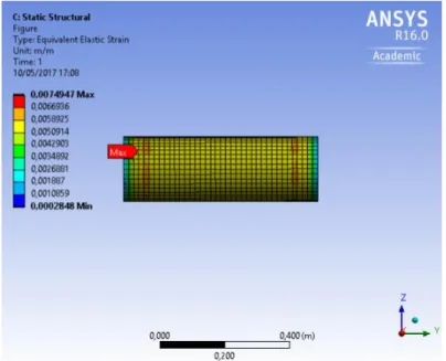
Fig. 30 Equivalent Elastic Strain (m/m) for 2.23 MPa external pressure - POM ... 44
Fig. 32 Stress/thickness relation on Syntactic Foams ... 47
Fig. 33 Representation of rigidity rings ... 48
Fig. 34 First model Assumed for the main structure ... 50
Fig. 35 Relative coordinates of the main joints ... 51
Fig. 36 Buckling factor function of boundary conditions ... 54
Fig. 37 - Representation of thickness deformation ... 60
Fig. 38 Steel Structure ... 61
Fig. 39 POM structure ... 68
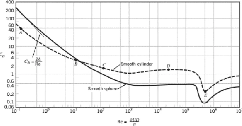
Fig. 40 Drag coefficient as a function of the Reynold's number and geometry ... 70
Fig. 41 Structure dimensions - Steel ... 70
Fig. 42 Structure dimensions - POM ... 72
Fig. 43 Total Deformation (displacements in m) on Load Case no 1 - Steel Structure ... 74
Fig. 44 Equivalent Elastic Strain on Load Case no 1- Steel Structure ... 74
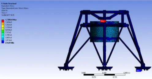
Fig. 45 Equivalent von-Mises Stress (Pa) on Load Case no 1- Steel Structure ... 75
Fig. 46 Total Deformation (displacements in m) on Load Case no 1 - POM Structure. ... 75
Fig. 47 Equivalent Elastic Strain on Load Case no 1- POM Structure. ... 75
Fig. 48 Equivalent von-Mises Stress (Pa) on Load Case no 1- POM Structure. ... 76
Fig. 49 Total Deformation (displacements in m) on Load Case no 2 - Steel Structure. ... 77
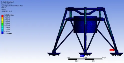
Fig. 50 Equivalent von-Mises Stress (Pa) on Load Case no 2- Steel Structure. ... 77
Fig. 51 Equivalent von-Mises Stress (Pa) on Load Case no 2- Steel Structure. ... 78
Fig. 52 Total Deformation (displacements in m) on Load Case no 2 - POM Structure. ... 78
Fig. 53 Equivalent Elastic Strain on Load Case no 2- POM Structure. ... 78
Fig. 54 Equivalent von-Mises Stress (Pa) on Load Case no 2- POM Structure. ... 79
Fig. 55 Total Deformation (displacements in m) on Load Case no 3 - Steel Structure. ... 80
Fig. 56 Equivalent Elastic Strain on Load Case no 3- Steel Structure. ... 80
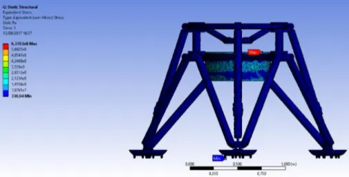
Fig. 57Equivalent von-Mises Stress (Pa) on Load Case no 3- Steel Structure. ... 80
Fig. 58 Total Deformation (displacements in m) on Load Case no 3 - POM Structure. ... 81
Fig. 59 Equivalent Elastic Strain on Load Case no 3- POM Structure. ... 81
Fig. 60 Equivalent von-Mises Stress (Pa) on Load Case no 3- POM Structure. ... 81
Fig. 61 Total Deformation (displacements in m) on Load Case no 4 - Steel Structure. ... 83
Fig. 62 Equivalent Elastic Strain on Load Case no 3- Steel Structure. ... 83
Fig. 63 Equivalent von-Mises Stress (Pa) on Load Case no 4- Steel Structure. ... 83
Fig. 64 Total Deformation (m) on Load Case no 4 - POM Structure. ... 84
Fig. 65 Equivalent Elastic Strain on Load Case no 4- POM Structure. ... 84
Fig. 67 Total Deformation (displacements in m) with Drag force- Steel Structure. ... 86
Fig. 68 Equivalent Elastic Strain with Drag force - Steel Structure. ... 86
Fig. 69 Equivalent von-Mises Stress (Pa) with Drag force - Steel Structure. ... 87
Fig. 70 Total Deformation (displacements in m) with Drag force - POM Structure. ... 87
Fig. 71 Equivalent Elastic Strain with Drag force - POM Structure. ... 87
Fig. 72 Equivalent von-Mises Stress (pa) with Drag force - POM Structure. ... 88
Fig. 73 The first 6 eigen-frequencies for the proposed Steel Structure. ... 89
Fig. 74 Mode 1 Shape – 48.283 Hz ... 89
Fig. 75 Mode 2 Shape - 48.397 Hz ... 90
Fig. 76 Mode 3 Shape – 79.789 Hz ... 90
Fig. 77 Mode 4 Shape – 79.789 Hz ... 90
Fig. 78 Mode 5 Shape – 108.87 Hz ... 91
Fig. 79 Mode 6 Shape – 108.96 Hz ... 91
Fig. 80 The first 6 eigen-frequencies for the proposed POM Structure. ... 92
Fig. 81 Mode 1 Shape – 23.301 Hz ... 92
Fig. 82 Mode 2 Shape – 23.4 Hz ... 92
Fig. 83 Mode 3 Shape – 32.279 Hz ... 93
Fig. 84 Mode 4 Shape – 32.327 Hz ... 93
Fig. 85 Mode 5 Shape - 42.927 Hz ... 93
Fig. 86 Mode 6 Shape - 43.037 Hz ... 94
Fig. 87 Stress in function of External Pressure - Structural Steel ... 103
Fig. 88 Stress in function of External Pressure - Stainless Steel ... 104
Fig. 89 Stress in function of External Pressure - Titanium ... 105
Fig. 90 Stress in function of External Pressure - Aluminium ... 106
Fig. 91 Comparison of metal material stress ... 107
Fig. 92 Stress in function of External Pressure – PTFE ... 108
Fig. 93 Stress in function of External Pressure – FEP ... 109
Fig. 94Stress in function of External Pressure - FPA ... 110
Fig. 95 Stress in function of External Pressure – LDPE ... 111
Fig. 96 Stress in function of External Pressure HDPE ... 112
Fig. 97 Stress in function of External Pressure - UHMW-PE ... 113
Fig. 98 Stress in function of External Pressure - PBI ... 114
Fig. 99 Comparison of polymeric material stress ... 115
Fig. 100 Stress in function of External Pressure - 94Al2O3 ... 116
Fig. 102 Stress in function of External Pressure - Si3N4 ... 118
Fig. 103 Comparison of ceramic material stress ... 119
Fig. 104 Main Support (Upper Part) - Load Case 1 - Steel ... 120
Fig. 105 Main Support (Upper Part) - Load Case 2 - Steel ... 120
Fig. 106 Main Support (Upper Part) - Load Case 3 - Steel ... 121
Fig. 107 Main Support (Upper Part) - Load Case 4 - Steel ... 121
Fig. 108 Main Support (Upper Part) - Load Case 1 - POM ... 122
Fig. 109 Main Support (Upper Part) - Load Case 2 - POM ... 122
Fig. 110 Main Support (Upper Part) - Load Case 3 - POM ... 123
Fig. 111 Main Support (Upper Part) - Load Case 4 – POM ... 123
Fig. 112 Main Support (Inferior Part) - Load Case 1 - Steel ... 124
Fig. 113 Main Support (Inferior Part) - Load Case 2 - Steel ... 124
Fig. 114 Main Support (Inferior Part) - Load Case 3 - Steel ... 125
Fig. 115 Main Support (Inferior Part) - Load Case 4 - Steel ... 125
Fig. 116 Main Support (Inferior Part) - Load Case 1 - POM ... 126
Fig. 117 Main Support (Inferior Part) - Load Case 2 - POM ... 126
Fig. 118 Main Support (Inferior Part) - Load Case 3 - POM ... 127
Fig. 119 Main Support (Inferior Part) - Load Case 3 – POM ... 127
Fig. 120 Secondary Support - Load Case 1 - Steel ... 128
Fig. 121 Secondary Support - Load Case 2 - Steel ... 128
Fig. 122 Secondary Support - Load Case 3 - Steel ... 129
Fig. 123 Secondary Support - Load Case4 - Steel ... 129
Fig. 124 Secondary Support - Load Case 1 - POM ... 130
Fig. 125 Secondary Support - Load Case 2 - POM ... 130
Fig. 126 Secondary Support - Load Case 3 - POM ... 131
Fig. 127 Secondary Support - Load Case 4 – POM... 131
Fig. 128 Columns - Load Case 1 - Steel ... 132
Fig. 129 Columns - Load Case 2 - Steel ... 132
Fig. 130 Columns - Load Case 3 - Steel ... 133
Fig. 131 Columns - Load Case 4 - Steel ... 133
Fig. 132 Columns - Load Case 1 - POM ... 134
Fig. 133 Columns - Load Case 2 - POM ... 134
Fig. 134 Columns - Load Case 3 - POM ... 135
Fig. 135 Columns - Load Case 4 - POM ... 135
Fig. 137 Superior Hoop - Load Case 2 - Steel ... 136
Fig. 138 Superior Hoop - Load Case 3 - Steel ... 137
Fig. 139 Superior Hoop - Load Case 4 - Steel ... 137
Fig. 140Superior Hoop - Load Case 1 - POM... 138
Fig. 141 Superior Hoop - Load Case 2 - POM ... 138
Fig. 142 Superior Hoop - Load Case 3 - POM ... 139
List of tables
Table 1 Active Manned Submersibles ... 5
Table 2 ROV Groups [15] ... 6
Table 3 Mechanical Properties and Ratio Price/Weight for different materials [5][35][36][37]. ... 16
Table 4 Mechanical properties and Price/kg ratio of different metallic materials [37]. ... 24
Table 5 Mechanical properties and Price/kg ratio of different composite materials [37]. ... 25
Table 6 Mechanical properties and Price/kg ratio of different ceramic materials. ... 26
Table 7 Mechanical properties and Price/kg ratio of fluoropolymers [49]. ... 27
Table 8 Mechanical properties and Price/kg ratio of polyethylene polymers [49]. ... 27
Table 9 Mechanical properties and Price/kg ratio of POM and PBI [49]. ... 28
Table 10 Mechanical properties of MZ-24 ... 28
Table 11 Comparison of angles of coverage underwater with a flat port and air ... 31
Table 12 Mechanical properties and Price/kg ratio of Glass and Acrylic [1] ... 32
Table 13 Pumped Water Variable Buoyancy System Valves functioning ... 36
Table 14 Tube thickness for each material... 41
Table 15 Equivalent Stress resultant from different loads ... 42
Table 16 Maximum ANSYS values for POM ... 44
Table 17 Depth range for each material... 45
Table 18 Ratio €/m for each material for maximum depth ... 46
Table 19 Syntactic Foam ANSYS analysis ... 46
Table 20 ANSYS and theoretical values comparison for POM cylinder ... 49
Table 21 Imperfection Factors ... 55
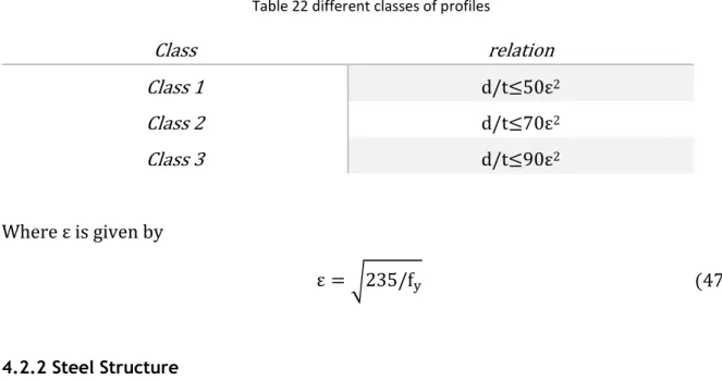
Table 22 different classes of profiles ... 56
Table 23 Buckling analysis for steel frame main supports ... 56
Table 24 Buckling analysis for steel frame main supports - chosen profile ... 57
Table 25 Buckling analysis for steel frame secondary supports ... 58
Table 26 Buckling analysis for steel frame secondary supports - chosen profile ... 59
Table 27 Bending radius for steel profiles ... 60
Table 28 Steel Structure submersed volume ... 61
Table 29 Buckling analysis for POM frame main supports ... 63
Table 30 Safety factor for polymeric buckling analysis ... 64
Table 31 Buckling analysis for POM frame main supports - chosen profile... 65
Table 32 Buckling analysis for POM frame secondary supports - chosen profiele ... 66
Table 34 Structural Components Stress - Load Case 2 ... 79
Table 35 Structural Components Stress - Load Case 3 ... 82
Table 36 Structural Components Stress - Load Case 4 ... 85
Table 37 Steel Structure Vibration modes' frequencies ... 89
Table 38 POM Structure Vibration modes' frequencies ... 91
Table 39 Maximum Stress Values - Steel Structure ... 95
Table 40 Maximum Stress Values - POM Structure ... 96
Table 41 Structural Steel Analysis Values ... 103
Table 42 Stainless Steel Analysis Values ... 104
Table 43 Titanium Analysis Values ... 105
Table 44 Aluminium Analysis Values ... 106
Table 45 PTFE Analysis Values ... 108
Table 46 FEP Analysis Values ... 109
Table 47 FPA Analysis Values... 110
Table 48 LDPE Analysis Values ... 111
Table 49 HDPE Analysis Values ... 112
Table 50 UHMW-PE Analysis Values ... 113
Table 51 PBI Analysis Values... 114
Table 52 94Al2O3 Analysis Values ... 116
Table 53 96Al2O3 Analysis Values ... 117
1 Introduction
1.1 Ocean Exploration
The ocean carries a fundamental role in human life, from the climate pattern, to the air we all breathe [1]. However, despite its value, the ocean remains highly unknown, inhibiting us from exploiting full advantages of all its potentialities.
Citing The Ocean Portal Team, “Deep below the ocean’s surface is a mysterious world
that takes up 95% of Earth’s living space.” [2]. The deep-sea homes a large diversity of
geological features and living beings, whose adaptation to the harsh medium characterized by cold temperatures, high pressure and low light, created unique and fascinating creatures with special features, that can be exploited in many areas of industry.
The Ocean Exploration, mainly laying on deep-sea, will give us new information on marine geology and biology, which may allow to discover new potentialities and resources that so far are not in use. Water quality, mineral resources, biological stock evaluation, biodiversity protection against invasive species, determination of highly valued species, are some examples of potentialities ocean exploration offers.
One of the main fields that deserves an increased focus are benthic macroalgae, given their industrial potential and their constitution that can be highly valuable in food, feed, pharmaceutical and cosmetic industries. The main advantages of macroalgae as a biological resource are their fast grown, the ability of growth in all climatic zones, their high content of valuable carbohydrates, proteins and lipids [3]. Regarding the ecological functioning of marine ecosystems, these seaweeds have an essential part since they are a habitat for other leaving creatures [4] and they are one of the main producer of nutrient in the benthic food chain, therefore, a rigorous control of seaweeds may have direct effect in the upper food chain levels.
From detecting a specific specie to mere curiosity, the study of the deep ocean is something that have always intrigued scientists and engineers, however the water barrier that split us from the seafloor has been a major challenge [5].
Cornelis Drebbler built the first submarine ever made, in 1623: a machine comprised by an outer hull of greased leather over a wooden frame that could operate to depths of 3.5 to 5 m. One of the first successful technologies developed to know the fauna and flora living on the sea bottom, and turning point for deep-sea exploration paradigm, was the marine
organisms from seafloor. With this technology, simply composed by a net and a digging mechanism, samples were collected at 548.64 meters deep in the ocean (300 fathoms). Up to date, it was believed that were no life under 200 m [6], since there was no light. With this discovery, there was a bloom in deep-sea exploration technologies development.
The first advanced engineered technology came up in the 1950’s with the first untethered manned submersibles, like ALVIN. The first unmanned vehicles appeared one decade after, and the last 25 years of the XX century was the main period for development of Autonomous Unmanned Vehicles [5]
1.2 Algae-to-MArket-Lab IdeAs – TECMAR - INEGI
This project can be seen as a part of a project entitled AMALIA. This project counts on the participation of higher education institutions, research units, companies and local development associations, in particular INEGI - Institute Of Science And Innovation In Mechanical And Industrial Engineering, which is a research and technology organization, acting as an interface between the university and the industry, and it is manly focused on applied research and development, innovation and technology transfer activities [7]. The Sea Technologies group (TECMAR), an INEGI sector, where this dissertation project was developed, aims to promote and create technologic solutions that can fit industrial needs, particularly economy of Sea, through innovation of traditional marine activities or through the emergence of new high value economic activities (on the domain of biotechnology, energy, robotics). This working group skills comprise the hydrodynamic evaluations of anny offshore and marine structures (such as SPARs, FPSOs, TLP, energy converters), design and mooring systems global performance analysis, dynamic stability analysis, among others.4
The surge of invasive macroalgae species has becoming a major concern both in an ecological and economic level. These species displace natives, causing the loss of their genotype, affecting marine habitats, ecosystem processes, and food-web properties, having impact in human health. In addition, all of these lead to an economic loss [8].
Instead of looking at this event has a threat, is possible to see it as a promising opportunity.
The AMALIA (Algae-to-Market Lab IdeAs) project aims to exploit these seaweed species, in the northwest of the Iberian Peninsula, considering their industrial potential and their compounds that can be used in the food, feed, pharmaceutical and cosmetic industries, thus, increasing their value and contributing to the economy. Besides, the effective control of these macroalgae will lead to an improvement in the quality of the oceans.
To monitor the appearance of these macroalgae, advanced engineering and imaging systems and solution will be deployed into the seafloor to provide real-time information regarding the appearance and quantities of algae.
1.3 Project objectives
Underwater operations in deep-sea have a major importance in the knowledge of both chemical and physical properties of water, and also in the study of its biodiversity. The seabed is the habitat for a great variety of organisms, therefore constitutes a distinct stratum for benthic life [9].
The analysis of this environment can be conducted either in-situ or ex-situ, regarding where this analysis is taken: directly from deep-sea or from a samples extracted from their natural habitat, respectively.
In ex-situ, when brought up to the surface, samples are subjected to hydrostatic pressure and temperature variations; it consequently becomes difficult to collect accurate data for further analysis. It is therefore desirable to carry out deep-sea experiments and measurements in-situ, avoiding artefacts induced by disturbance. Such operations are carried out using manned or unmanned vehicles that explore the sea floor whose main goal is to collect all data needed while minimizing the possible perturbation it may cause to seabed and samples during both landing and operation [9].
The main objective of this project is to design a submersible modular system for seashore monitoring, capable of conducting in-situ analysis. During this report, the procedure to select the system geometry and construction materials for different components it will be describer, as different load cases. Other parameters were considered as vertical movements’, hydrodynamic design, methods for launching, landing and recovering, sampling, observation and measurement techniques, choice of electronic components, as sensors, and, for last, energy requirements, are specific points to be considered when designing these vehicles in order to obtain successful results, regarding data collect [9].
(a) (b)
2 State-of-the-art
2.1 Deep-sea Technologies
Explore seafloor is an appealing topic since it is the largest geographic feature in our planet. It will therefore boost the need for new and more developed marine technologies for ocean exploration and discovery [10].
These technologies can be distinguished either if they are manned or not, or based on its autonomy.
2.1.1 Manned Submersibles
Manned vehicles are vehicles that drive with, at least, one operator into deep-sea. For
Manned Underwater Vehicles Committee, these vehicles can be divided in two different
groups: GROUP 1 – HADAL Depth, for a working depth over 1000m; and GROUP 2 – Deep Ocean, for working depth between 250 and 1000 m [11]. With these deep diving capabilities, manned submersible vehicles are able to explore approximately 98% of the ocean floor [10].
The main advantages of manned submersibles lies ‘in placing the human eye, hand and
brain at the point of observation’, as it is said by R.A. Geyer in Submersibles and Their Use in Oceanography and Ocean Engineering [12]. This means that a closer and more direct look can
be took, allowing one to pick out more details, thus improving accuracy when compared to less sophisticated remote system. The most durable virtue for manned submarines is ‘(…) the
ability to react, to pursue the unexpected, to alter plans quickly and continuously in response to a changing situation (…)’. Despite all this, it requires complex, expensive, and non-optional
life-support and safety systems, thus less preferable for deep-sea exploration. An additional disadvantage, when compared to other technologies, is the limitation exploration period, once it does not allow long-term operations [12].
One of the most known manned submersible project is de Deepsea Challenger, where a partnership between Woods Hole Oceanographic Institution (WHOI) and James Cameron an explorer and filmmaker, culminated in a one single person expedition to the deepest point of the world’s Ocean, the Mariana Trench, at the depth of nearly 11 000 m. The Deepsea Challenger construction was secretly made under the leadership of the Australian engineer Ron Allum, in a partnership with the National Geographic Society and with support from Rolex. The vehicle descend speed was about 2.6 m/s, taking 2 hours to reach the ocean bottom. There, due to the sub battery life, the expeditor had 6 hours to ‘(…) explore the
deep-ocean frontier for clues new life-forms and the forces that shape our planet (…)’, as it is said in NATIONAL GEOGRAPHIC magazine [13], which reported the project. On ascent, as a result of
the sub technology, the velocity of the vehicle achieved approximately 3.6 m/s, reaching the surface one hour after leaving the seafloor.
Manned submersible vehicles may present some risks and dangers to its operator(s). Some of those where mentioned by James Cameron. The possibility of implosion due to miscalculated sphere project; penetration failure; freezing; fire; adrift, when only some of the ballast weight, whose liberation allows the sub to ascend, drops, causing the hazard of getting
lost in the water column; hypothermia and hyperthermia are some examples. All of these present a major life risk [13].
Alongside this manned submersible, there are many other currently active vehicles, Table 1 Active Manned Submersibles presents some of the models.
Table 1 Active Manned Submersibles
Deepsea Challenge JIAOLONG SHINKAI 6500
Depth 11 000 m 7000 m 6500 m
Capacity 1 3
Operator Woods Hole Oceanographic
Institution (WHOI)
China National Deep Sea Centre
Japan Agency for Marine-Earth Science
& Tech (JAMSTEC)
Country USA China Japan
MIR 1 NAUTILE ALVIN
Depth 6000 m 6000 m 4450 m
Capacity 3 3 3
Operator PP Shirshov Inst. of Oceanology
(RAS)
IFREMER Woods Hole Oceanographic
Institution (WHOI)
2.1.2 Remotely Operated Vehicle
According to Remotely Operated Vehicle Committee of the Marine Technology Society, a Remotely Operated Vehicle, further referred to as ROV, is ‘(…) a tethered
underwater robot that allows the vehicle's operator to remain in a comfortable environment while the ROV works in the hazardous environment below.’
A ROV system is composed by a vehicle connected to the control van via a tether, which comprises a group of cables responsible to transmit video and data signal back and forth between the vehicle and the operator, as well as carry electrical power, a handling system for cable dynamics control, a launch system and power supplies. Additional equipment needed for data collecting may be assembled to the vehicle, fitting its requirements. Such equipment can be video cameras, sonar systems, lights, or an articulating arm [14].
Due to high drag on the vehicle and tether cable, ROVs are slow in speed, however, they can move with full control along all axes.
Concerning size, depth capability, on-board horsepower, and whether it has or not hydraulic components, ROV systems can be grouped as it is shown in the following table.
Table 2 ROV Groups [15]
Class Depth Type Power Observations
Micro Observation <100 m Low Cost
Small Electric
<5 hp Less than 3 kg
An alternative to a diver for places he may not be able to reach
Mini Observation <300 m Small
Electric <10hp Around 15 kg Light/Medium Work Class <2000 m Medium Electric/Hybrid <100 hp
Can be made from polymers (e.g., polyethylene) Observation/Light Work Class <3000 m High Capacity Electric <20 hp
Heavy Work Class /Large Payload
<3000 m High Capacity
Electric/Hybrid <300 hp
Ability to carry at least two manipulators
Observation/Data Collection
>3000 m Ultra-Deep
Electric <25 hp
Heavy Work Class /Large Payload
>3000 m Ultra-Deep
Electric/Hybrid <120 hp
Ability to carry at least two manipulators
Some ROVs are capable of achieving 6000m depth, for example KIEL 6000 from GEOMAR [16], presented on Fig. 2 (b) used in a ‘live-boating-mode’, by means of a deep-sea glass fibre cable; and VICTOR 6000 [17], show on Fig. 2(a), from IFREMER. With this working depth, both of these ROVs can reach more than 90% of the seafloor.
Fig. 2 Remotely Operated Vehicle (a) ROV VICTOR 6000; (b) ROV KIEL 6000
2.1.3 Unmanned Submersibles Autonomous Underwater Vehicles
Autonomous Underwater Vehicles, further referred to AUVs, are unmanned and self-propelled vehicles, usually deployed into the sea from a surface vessel. AUVs can operate independently for periods of a few hours to several days [18].
These vehicles differ from ROVs in the way that AUVs are un-tethered to the host vessel; therefore, their speed, mobility and spatial range are less constrained. Nonetheless, ROVs present advantages in real-time communication and power transmission.
AUVs are able of maintaining a linear trajectory through the seawater, just unlike submarines gliders, which due to its variable buoyancy system, profile the water column in a sawtooth pattern by shifting small amounts of ballast to dive and climb. The glides moves both horizontally and vertically. These vehicles can follow a pre-programmed course and they are able to navigate using a combination of Ultra Short Base Line acoustic communication, GPS positioning, and inertial navigation; or using arrays of acoustic beacons on the seafloor.
Operations with these vehicles cannot be done everywhere; therefore, there is a need to consider some particular aspects. Usually, the maximum speed of AUVs used for sea exploring is 1.5-2.0 m/s, this value can be influenced by currents, namely tidal, approaching or exceeding these velocities. This may affect data quality collect due to navigational drift [18]. The ability to operate close to the seabed, less than 5 m altitude in low relief, allows these vehicles to collect seafloor mapping, profiling and imaging data of far higher spatial resolution [18].
AUVs may have a torpedo-shape, the most usual, or a more complex configuration, allowing them to move in slower motion and across complex terrain. These are commonly related with hovering navigation and hybrid AUV/ROV capabilities [10].
Some AUVs examples are Sentry from WHOI, capable of exploring down to 6000 meter, presents a complex shape, allowing it to carry a range of devices. Sentry AUV (Fig. 3 (a)) produces ‘(…) bathymetric, sidescan, subbottom, and magnetic maps of the seafloor and is
mid-ocean ridges, deep-sea vents, and cold seeps at mid-ocean margins(…)’ as it is said in WHOI
website. It also can locate and quantify hydrothermal fluxes [19].
Another example is the Bluefin-21 (Fig. 3(b)), from Bluefin Robotics, a modular vehicle able to carry different sensors and payloads. It presents high energy capacity that grant long-term operations at big depths, up to 4500 meters [20]. DEPTHX AUV - Deep Phreatic THermal
eXplorer (Fig. 3 (c)) from Stone Aerospace is another AUV example. It was the first mobile
robotic system to implement 3D-SLAM (Simultaneous Localization and Mapping) as part of real-time navigation engine, the first to explore and map a subterranean cavern – a hydrothermal spring, and the first robotic system able to decide autonomously the precise moment and place to collect biological data [21].
Fig. 3 Autonomous Underwater Vehicles (a) AUV SENTRY; (b) AUV BLUEFIN-21; (c) AUV DEPTHX; (d) Hybrid Remotely Operated Vehicle Nereus
Hybrid Remotely Operated Vehicle
The AUV/ROV hybrid, commonly known as HROP (Hybrid Remotely Operated Vehicle), e.g. Nereus (Fig. 3 (d)), from WHOI, which was the highest level of development concerning the deep-sea unmanned vehicles. It was able to operate in two different modes, for deeper or more expansive areas it operates untethered as an AUV, and it could be converted to a ROV to enable close-up images and sampling [22]. Nereus was lost at sea while exploring the Kermadec Trench at approximately 10,000 meters [23].
Another example of AUV/ROV hybrid is the Promare’s 11k (Fig. 4). This is a low cost solution, able of achieving 11 000 meters, with a total weight of 60 kilograms. What controls all vehicle functions is a single board computer, which, in AUV mode the system is completely programmed by it. When it comes to ROV mode, the vehicles control is via a fibre-optic connection that provides two channel of communication: one for operator command and sensor measurements, the other aims to provide real-time high definition video signals [24].
The most peculiar feature of this technology is that most of the hardware is embedded in a glass sphere, held in place by a thermoplastic structure [24].
Fig. 4 Hybrid Remotely Operated Vehicle 11k from Promare
Benthic Landers
It is known as ‘Benthic Lander’, commonly just lander, any unmanned, autonomous and instrumented vehicle, which is deployed in the seafloor, unattached to any cable, to gather physical and chemical variables in situ over a period of time. The lander operations may be taken in a few days, for biological studies, to several years, for physical oceanography studies [9][10].
The deployment can be in a free fall mode or in a high precision location to measure geomorphological features using a special design lunching device connected to a crane from the ship or vessel in the surface. The climb is usually made by the release of ballast weights or using variable bouncy systems. They are then recovered and put on board, lifted by cranes [9]. 2.2 Benthic Landers
2.2.1 The Role of Benthic Landers in the science fleet
Given the concerns regarding manned and tethered submersibles, there was a need to develop a vehicle able to perform underwater without any physical connection to the surface. However, underwater operations present many engineering challenges, for example, electromagnetic waves that hardly spread underwater, creating communications barriers between the surface and the vehicle [5]. Therefore, the emergence of a completely autonomous vehicle or structure would ease the deep-sea exploration. To this end, AUVs and Benthic Landers appear face to ROVs and Manned Submersibles.
AUVs and Benthic Landers can now easily be deployed into the ocean and retrieve the required data for a specific operation, however, when it comes to longer terms, or time lapsed comparison of static images, benthic landers present a clearly advantage. The fact of being completely static down the sea bottom, allows the lander to capture easily the same image over the time, allowing us to monitor the progress of macroalgae growth, for example. An AUV, for instance, could capture the same picture as well, however, it would need a much more power consumption, and a simple disturbance in the current could damage the image.
Another advantage of benthic landers is the fact that they can carry experiments and measurements in situ, reducing the possibility of artefacts on collected samples [9].
2.2.2 Types of Landers
As inserted in autonomic and unmanned deep-sea technology group, the depth rate of the site the lander will operate characterizes its category [5]. There are, therefore, the following categories:
Shallow Water; Mid-water; Deep-Water.
Shallow Water Landers
Shallow Water Landers usually operate at a maximum depth of 500 m [5], in a near offshore zone. Here, the main loads applied on the structure are dynamic forces caused by current or wind, thus it is very important to minimize the projected area of all equipment in order to reduce drag effect. The hydrostatic pressure they have to bear, compared to other loads, is negligible.
These landers are usually small and consequently the power supply equipment they carry may limit the operation term.
Mid-Water Landers
This category refers to Landers rated up to 2500 m [5]. In order to handle the hydrostatic pressures at the seafloor, these landers are typically voluminous. Since the water current at these depths is negligible, also the drag effect is, therefore the area is not a major facto to take in count.
Deep-water Landers
These landers operate at depths of more than 2500 m [5]. Here, the oceanographic pressures are enormous and thus the whole structure must be robust. To compensate its own weight on the recovery, it must have a complex variable buoyance system, however it my carry some risk of implosion of some of its equipment, e.g. glass spheres [9].
2.2.3 Mechanical and Material Issues Lander Design - Lander Structural Types
Regarding its applications and measuring instruments they carry, landers come in different shapes and sizes. They can generally be arranged in micro open-frame landers, macro open-frame landers, and flat shape landers [10].
Micro open-frame landers
A modular structure capable of carry instruments for monitoring and measuring in situ. These landers have an open-framed structure to minimize the effects of horizontal drag due to sea currents, allowing water to flow through the instruments and sensors payload. This type of lander has ballast weights in its bases that will be left in the bottom of the sea after its operation.
Examples of this kind of structures are the free falling baited landers HADAL – Lander A and HADAL – Lander B from WHOI, ROBIO and Medusa.
HADAL – Lander A and HADAL – Lander B
HADAL-Lander A, Fig. 5 (a), was equipped with a 3CCD hi-resolution colour video camera, mounted vertically at an altitude of 1 m, providing a visible area of 0.62 x 0.465 m, illuminated with two 50 W halogen lamps. I also had a Conductivity, Temperature and Depth (CTD) sensor that recorded temperature, salinity, and pressure every 10 seconds after deployment. Both camera and CTD probe were programmed a priori its deployment and all data were download after lifting and recovering [25].
The lander deliver system was comprise with the frame structure, made out of aluminium, with a mooring in which 6 buoyancy modules where couple off-line, three ballast weights and two acoustic release systems to discard the ballast weight. The total weight of the system during the free fall was 135 kg and reached the descent velocity of approximately 0.83 m/s. After the observational period, a unique acoustic command was sent in order to release the ballast, allowing the lander to ascend at the 0.5 m/s by virtue of the positive buoyant mooring [25].
HADAL-Lander A reached depths of 9800 m, prior to its loss in 2009 [25].
The lander deliver system of HADAL – Lander B, Fig. 5 (b), was similar to A, the only exception was that it comprised two acoustic release systems to jettison the ballast weight. These two are used in the event of failure of one of them. This lander reached 8074 m depth [26].
Despite this difference, the monitoring and observation equipment was different as well. It was equipped with a 5 megapixel digital camera and a CTD sensor. The camera was mounted vertically at an altitude of 1 m, providing a visible area of 0.62 x 0.465 m, as well [26].
Both of them were also equipped with small baited funnel traps, located on the extremity of each of the 3 legs or on the mooring line, used to collect samples [25][26].
Fig. 5 Benthic Landers - (a) HADAL Lander A; (b) HADAL Lander B
ROBIO
The RObust BIOdiversity, ROBIO (Fig. 6 (a)), is a baited lander built to monitor the fauna of benthic communities near possible subsea oil and gas exploration sites, autonomously, capable of reaching 3000 m. These landers are equipped with 3 Megapixel digital camera, able of taking up to 1400 frames per year, and other sensors to characterize currents properties such as direction, velocity and salinity [10].
It has two different deployment methods: i) tethered two meters above seabed with the camera positioned vertically, pointed downward looking at the bait; ii) landed on the sea-floor, with the camera pointed outward [27].
Medusa
The Medusa lander (Fig. 6 (b)) is deployed in a free fall mode and recover in the surface after the acoustic signal that allow the ballast release. It uses red light illumination, which is not visible to most of deep-sea fauna, and it is equipped with a camera system that is able to amplify both this dim illumination as bioluminescence. This camera will record for 24-hour time intervals for up two days [28]. The data is not transmitted in real time; therefore, the analysis can only be made after its recovery [29].
This lander uses two different bait systems: a bait box on the end of the bar, mounted directly in front of the camera; or a lure simulating a bioluminescent jelly to attract large predators in the area. These 16 blue LEDs system called e-jelly (Fig. 6 (c)) simulate the signal that Atolla jellyfish produces in need for help [28].
Fig. 6 Benthic Landers - (a) ROBIO Lander; (b) Medusa Lander; (c) Bait system e-jelly
Macro open-frame landers
These type of benthic landers are similar to the prior referred. However, these are used for longer term deployments whit a major number of equipment, which leads to a considerable size increase.
Some examples of these landers are K/MT 100 from KUM Kiel, DELOS and DOBO, both from Aberdeen Ocean Lab.
K/MT 100
The K/MT 100 Lander Fig. 7 (a) comprises an open framed titanium structure with three legs, float units and measuring and monitoring equipment. The deployment is due the negatively buoyant ballasted lander that descents to the sea floor at a speed of 0.5 to 1.0 m/s where it lands. After the research period, steel weights are dropped through time release or an acoustic signal, switching the buoyancy to positive. After ascending to the surface, the research vessel recovers the lander. Its maximum operation depth e 6000 m [30].
Apart from the camera, the lander is also equipped with a benthic chamber. It is within the enclosed environment of this chamber where in situ experiments are carried out [9].
DOBO
Deep Ocean Benthic Observatory Fig. 7 (b) lander, known as DOBO, from Aberdeen Ocean Lab, is a benthic lander, which comprises a titanium frame, able to stay immersed for long term, up to 10 months, at a maximum depth of 2500 m operation. It has bait release systems that releases portions of bait at pre-programmed periods. This bait will attract benthic fauna, such as fish and invertebrates, photographed then by the camera incorporated in the lander [10].
This lander does not allow real-time data access, however, it has six to twelve months of data storage capability.
Fig. 7 Benthic Landers - (a) K/MT100 Lander; (b) DOBO Lander
DELOS A and DELOS B
The DELOS (Fig. 8) system comprises two environmental monitoring platforms: DELOS A, located within 50 meters of a seafloor wellhead; and DELOS B, located 16 km from sea floor structure. Each one of them comprises two parts: the seafloor anchor station, a robust triangular shaped structure made out of glass fibre designed to withstand 25 years; and observation modules, with a power storage enough for autonomous operation for 12 months. After this period, each platform requires intervention to recover observatory modules to the surface for calibration, data offload and servicing, for this operation is used a ROV. Therefore, for this system is not required a buoyancy system or other system for further recover [31].
Fig. 8 Benthic Lander DELOS
OBSEA
OBSEA lander (Fig. 9 (a)), a part of the FixO3 project, Fixed point Open Ocean Observatory, is a stainless steel structures designed for not permitting unauthorized manipulation, therefore protecting all the equipment. The cylinder that holds the control electronics is within this metal housing and it was projected to withstand water pressure at 300 m depth [32]. It will provide the interface between the marine cable, made up of six mono mode fibre optics for data transmission and two conductor tubes for power supply, and other instruments connected to the observatory [33].
After deployed, these platforms will be connected to shore by the marine cable, which allows continuous data flow and to supply enough power to operate [33].
Flat Shape Landers
The prior design concepts lies in the minimization of the projected surface area, orthogonal to the current movement direction, in order to reduce horizontal drag effect. This new concept uses a flat shape structure that seats in the seafloor. Thus, due to existence of the boundary layer and the fact that the wave induced effects decrease exponentially with the increase of the depth, this type of lander present low drag exposures. In addition, it uses its hydrodynamic effect to generate downward forces that anchors the system with the increase of seafloor currents [10].
K-Lander
This autonomous seabed sensor carrier, from KONGSBERG Modular Subsea Monitoring-Network (Fig. 9 (b)), has complete flexibility on sensor type installed and electric power from integral battery packs. It is a robust steel framed structure, which allows the implementation of multiple data source sensors allowing a wide area coverage [34].
It can operate for up to 24 months with low intervention at a depth rating of 2000 m.
Fig. 9 Benthic Landers - (a) OBSEA Lander; (b) K-Lander
Outer Frame Material
The lander is comprised by a basic support structure on which the equipment, ballast weight, and other mechanisms are mounted. When projecting, and posterior construction, these frames the main goal is to keep them as light as possible without compromising its mechanical properties, such as strength, in order to minimize the need for extra bouncy material. When deployed, the static stress that the lander is exposed is trivial, therefore, the main risks of mechanical damage occur during launch and recovery. For easier transport, most constructors designed outer frames that are readily dismantled [9]. Another crucial factor to
keep in mind when designing these devices is the non-inert sea environment, since it is highly corrosive.
The most common material is aluminium, but, despite of being relatively inexpensive and light, it is not strong as other materials and it needs some special welding equipment that may not be available in many ships [9].
Stainless steel is heavier than aluminium (about three times denser), however it presents better mechanical properties [9]. Its Modulus of Elasticity, E, is bigger than the other common materials module. The values can be compared in table 3.
Titanium is also a common material to build the outer frame; however, its higher price turns it into an unappealing solution for applications that do not require its properties. Titanium presents some disadvantages apart from its cost, such as the difficulty of weld it and polish it. A good quality welding must be undertaken in an oxygen free environment, and polishing titanium must have considerable precaution since its dust can ignite spontaneously [9].
Galvanized steel is a less likely alternative since it presents several disadvantages. Closed sections of the frame, such as cylindrical tubes, are difficult to galvanize internally, leaving the frame vulnerable to corrosion. In order to reduce this problem, constructors recommend the use of sacrificial anodes (made of Zn or Mg) [9].
To give the structural shape and strength to the frame, composite structures have not been used yet, due to their low behaviour under high external pressures [9]. However, in order to minimise corrosion, composites overwrapped profiles are an alternative [31].
The table below presents the average values for mechanicals properties density and Modulus of Elasticity, and the average price per kilogram of most used materials. Fibres and a matrix, a resin, comprise composite materials. Thus, these materials combine both components mechanical properties. For comparison, the resin chase was Epoxy.
Table 3 Mechanical Properties and Ratio Price/Weight for different materials [5][35][36][37].
Material Density [kg/m3] E [GPa] €/kg (14 Feb 17) Corrosion Resistance
Stainless Steel 7800 198 2.01 Fair
Aluminium 2699 68 1.41 Fair
Titanium 4500 116 3.45 Very Good
Epoxy + Carbon fibre reinforcement* 1575 141.5 36.20 Excellent
Epoxy + Glass fibre (S Class) reinforcement* 1905 47.7 23.20 Excellent
Epoxy + Aramid fibre reinforcement* 1380 70 58.00 Excellent
Housing Material
Many of the equipment used in landers are designed to operate at one atmosphere. So, most of them, such as non-compensable batteries, computer electronics, etc., must be placed in housings at this pressure condition. Since these housings’ walls bear a big differential pressure between the internal one atmosphere pressure and the relatively higher exterior hydrostatic pressure, it is crucial that the housing material grants high strength [5]. This material selection presents a major concern regarding the final weight of the structure, and its shape is a crucial factor as well, since it will be the lander’s component with the biggest projected area (orthogonal to current movement), consequently the one that will create a bigger drag.
With the big surface area of the housing, corrosion is another critical problem to be solved. Unless a composite or a ceramic material is used, the harsh environment of the ocean will corrode the metal housing and, as it was said in the previous section, some techniques must be used in order to decrease this risk. One of the most commonly solutions used is to attach a sacrificial anode or a more galvanically active material, e.g. zinc, that would corrode preferentially before the housing [38].
In some cases, the components that will take part in the lander are pressure compensable, thus, they experience a high and uniform pressure. To prevent the equipment from getting wet, these are normally enclosed in an oil-filled housing. Although this set up presents an advantage concerning the water bouncy, since the oil density is lower than the water’s, it is not recommended for long-term deployments once it need regular maintenance.
Variable Buoyancy Systems
To lift off the seafloor and following ascending, landers use positive bouncy. Depending on the system they use, after the surface signal is sent, vertical forces will be no longer in static equilibrium, and, therefore, a vertical movement will be generated by impulsion.
Variable buoyancy systems (VBSs) provide the lander the capacity of controlling descendent and ascendant speed; relocating [10]; low operating cost and energy consumption; increased payload capacity; simplified pre-dive maintenance [39]; and better lander control. Some VBSs already used are: Discharge Variable Buoyancy Systems; Pumped
Water Variable Buoyance System; One-way Tank Flood Variable Buoyancy System and Pumped Oil Variable Buoyancy System [39].
2.2.4 Sea keeping and Mooring System
It is a major concern that the lander stays in the required position to collect the desirable data. In order to obtain that, there are some aspects which must take into account regarding its landing, descent movement and its stationary properties.
Deployment
As was previously said the deployment of the lander can be made in a free fall mode or, if the operation requires high precision positioning, using a special design-lunching device connected to a crane from the vehicle in the surface [10].
Depending on the lander’s dimensions and weight, its transportation to the deployment site may vary from a simple rib boat to a ship-of-opportunity equipped with a crane and winch system, having direct effect in the final coast. Therefore, the final structure must be able to fit a standard sized maritime container of 20’ x 8’ x 8.6’ [40].
Descent and Landing
The projected lander’s position in the ocean’s floor before its deployment is strongly conditioned by its descent movement, which, in turn, is highly affected by the currents within the ocean water column. This, allied to lander’s sink speed, can be the cause of a crucial obstacle in keep the lander in its desirable position [9].
To oppose these effects, some techniques are used. In order to obtain greater dive velocities, the structure must not comprise a big projected area in the dive direction. This will reduce the hydrodynamic effects, such as drag effects and added mass effects, on the lander not deviating it from its planned dive path [9].
Regarding the lander’s landing, the descent speed is also important, once, if it is too fast, it is likely to produce great disturbance among the seafloor and it will be driven deeper into the sediment, increasing the risk of the lander becoming trapped in sticky bottom sediments [9].
However most landers successfully land by simply crash into the bottom, to minimize the impact, the seafloor disturbance, and the risk above mentioned, some techniques have been developed in order to adjust lander’s sink speed. When launched, landers have a negative buoyancy, which value, as it sinks into the water column, decreases due to the increase of seawater density. Some landers have a ballast weight suspended beneath it that will firstly reach the bottom. When this happens, the lander buoyancy has already turn into positive and, therefore, it will not hit the floor, keeping suspended. An acoustic command from the surface will then pull the lander onto the bottom at a small speed. This system is used in ROLAI2D Lander [9].
Other identical technique consists in the same principle of using buoyancy variations with suspended ballast bellow the structure; however, in this set the lander stays suspended, not touching the seafloor, not requiring the feet. This method is used in BANYULS and
GOTEBORG [9].
Concerning footpads, these must be big enough to prevent low penetration of the lander into the sediment. To prevent suction when recovery ascent movement starts, these footpads must have holes.
Mooring Systems
When in the seafloor the lander is constantly subjected to dynamic forces that may remove it from its desirable position. In order to prevent it, there are different approaches that engineers adopt. One of these systems is the mooring.
The purpose of a mooring system is to keep a floating structure on its desired position. The most common components of a mooring system are the mooring line and the anchors, connected with specific connectors.
The most used materials for the mooring line are wire, chain, or synthetic fibre rope or even, in some required cases, such as ultra-Deep-water station keeping, a combination of them. For permanent moorings in shallow waters up to 100 m, the most likely option is the chain [41].
Some mechanisms, such as Single Anchor Leg Mooring (SALM), a mooring line is not used. Instead, this mooring system comprises an anchoring structure with built-in buoyancy, anchored to the seabed by an articulated connection [42].
Regarding the anchoring component, this is the element where the system relies for its strength. There are three main types of anchors: Drag Embedment Anchors, Vertical Load
Anchors and Suction Anchors [41].
The first referred, Drag Embedment Anchors, are most used. Here, as the anchor is dragged along the seabed until it reaches the desirable depth, it uses soil resistance to get hold. It does not have a good performance when the anchor is under vertical forces; therefore, it is mainly used for centenary moorings [41].
Vertical Load Anchors work in a similar way as the previous described, however they can withstand both horizontal and vertical mooring forces. This kind of anchors is mainly used in Taut Leg Mooring Systems once the mooring line arrives at the seafloor with an angle [41]. At least, Suction Anchors systems performance lays in tubular pipes that are driven into de seabed, where a pump sucks out the water from the top of the tubular, pulling the pipe deeper into the seabed. This kind of anchors cannot operate in porous soils, such as gravel, once the water must not flow through the ground into installation [41].
3 Lander Structural Concepts
3.1 Project Requirements
This project started with the presentation of several concept models. These could be distinguished regarding their geometry and functionality. However, all of them must obey a list of rules and desires, named Project Requirements. This is a collection of requirements that should be followed in order to obtain the final desired product. These may be demanded (D), which, if not met, the final product is not truly complete, or desirable (d), which add value to the lander, making it more attractive in the industry market.
Regarding its geometry, we must consider the following requirements:
- D - Modularity – the lander must be projected considering that it must be able to engage more components regarding its operation.
- D - The centre of gravity of the lander must be below its centre of buoyancy.
- D - The total volume of the different lander modules disassembled must be inferior to 20’ x 8’ x 8.6’ (6.096 m x 2.4384 m x 2.62128 m).
- d - The projected area in the perpendicular plane to the currents direction must be minimized in order to reduce drag effects.
- d -The horizontal projected area must be minimizing as well to reduce the drag during the landing.
Considering the forces applied to the structures, the requirements are:
- D - The weight of the hardware module housing must be inferior to 6 kg; - D - Ability to adjust its ballast weight, and consequently, varying its
buoyancy;
- D - Landing velocity inferior to 0.5 m/s;
- D - Ability to handle hydrostatic pressures up to 2 MPa without damaging structural joints.
The demanded requirement for the lander’s modularity aims to adjust the components on the lander regarding its operation, therefore, among others, the lander should:
- D - Use an integrated hyper spectral camera to collect the possible source of seaweed in the ocean floor;
- d - Use a digital camera for image acquisition through the water column above the lander;
- Collect data regarding:
D - Water temperature; D - Salinity; D -Dissolved Oxygen; D - Turbidity; D - Ph; d - Depth;
d - Velocity of the currents; d -Wave amplitude.
For the material choice for the structure, the main requirements are: - D - Minimum working temperature of 0ºC;
- D - Chemically inert;
- D -Ability to handle hydrostatic pressures up to 2GPa without damage; 3.2 Lander Geometry
The geometry of a lander must be chosen regarding its application and requirements. The Lander developed within the scope of AMALIA project first priority is to detect invasive macroalgae species through their spectral reference; hence, the camera allocation is crucial. Aside from this, the lander must carry specific equipment able to characterize the environment of the macroalgae emergence. Once the need for sensors and monitoring equipment varies in accordance to our needs, the lander geometry must be able to adapt. Therefore the lander’s modularity is a central factor, as well.
As presented on the State-of-the-art, regarding their geometry, landers can be defined as ‘Open Frame’ or ‘Flat Shape’. In this specific application, invasive macroalgae will appear on the seafloor, at approximately 20 m depth; therefore, the camera must point upside down. For this main reason, the lander cannot be flat shaped. Thus, all concepts presented are open framed.
The first step consisted on reviewing existing benthic landers and understand why that was the chosen geometry and how could it be optimized. As the search progressed, a simple pen and a notebook were crucial to imagine the most suitable configuration foreseen for this application, presented on Fig. 10.
Fig. 10 Lander Design/Geometry sketches
After analysing some concepts proposed, some of them were modelled three-dimensionally using the software SOLIDWORKS for a better space perception.
Fig. 11 Modelled concepts of lander studied in this project
The chosen geometry for the lander in an initial approach was the represented on Fig. 12. As mentioned, this selection was based on the state-of-the-art, fitting both requirements and purposes. As a dynamic process, as the project progresses, the geometry may vary according to errors or necessities that may appear.
Fig. 12 Rendered model of the selected concept - SOLIDWORKS;
Next, it will be presented reasons behind this first approach for the lander’s geometry. In next chapters, some modules will be analysed in detail due to more likely to happen load cases.

![Fig. 19 (a) Concept for the Lunar Excursion Module (May of 1962) [60]; (b) Main support variable length, AMALIA Lander concept](https://thumb-eu.123doks.com/thumbv2/123dok_br/15677784.1063027/47.892.188.782.126.376/concept-excursion-module-support-variable-amalia-lander-concept.webp)