PIOTR SPUŚ
COST ANALYSIS OF REINFORCED CONCRETE
SLABS AND COLUMNS
ANÁLISE DE CUSTOS DE LAJES E PILARES EM
BETÃO ARMADO
PIOTR SPUŚ
COST ANALYSIS OF REINFORCED CONCRETE
SLABS AND COLUMNS
ANÁLISE DE CUSTOS DE LAJES E PILARES EM
BETÃO ARMADO
Dissertation was presented at University of Aveiro to fulfill the requirements for the degree of Master in Civil Engineering, held under the scientific guidance of Professor Miguel Morais, Assistant Professor, Department of Civil Engineering, University of Aveiro.
jury
president Prof. Doutor Carlos Daniel Borges Coelho
assistant professor, University o Aveiro
Dr hab. Dariusz Heim, prof. TUL
associate professor, Lodz University of Technology
Prof. Doutor Miguel Nuno Lobato de Sousa Monteiro de Morais assistant professor, University o Aveiro
agradecimentos Em primeiro lugar expresso o meu profundo agradecimento ao Professor Miguel Lobato de Sousa Monteiro de Morais pela sua disponibilidade, incentivo e compreensão durante a concretização deste trabalho.
Ao meu irmão e à minha mãe pelo carinho e apoio demonstrado. À Agusia, pelas palavras de apoio quando precisei.
Ao Dawid, pelo apoio nos maus momentos.
Aos amigos, Márcia e André, pela sua ajuda e sugestões com este trabalho. A todos… Muito Obrigado.
podziękowania W pierwszej kolejności pragnę podziękować mojemu promotorowi doktorowi Miguel Lobato de Sousa Monteiro de Morais za dyspozycyjność, cierpliwość i zrozumienie.
Profesorowi Dariuszowi Heimowi za umożliwienie mi wyjazdu do Portugalii. Mojemu bratu i mojej mamie za troskę i wsparcie.
Agusi, której zawdzięczam bardzo dużo, za okazaną bezinteresowną pomoc i bycie wzorem pracowitości.
Dawidowi za wysłuchanie, gdy tego potrzebowałem.
Moim kolegom z wydziału, Marcia i André, za zainteresowanie i praktyczne wskazówki.
keywords rainforced concrete, design, safety check, ultimate limit states, cost analysis, flat slabs, reinforced concrete columns
abstract The construction industry is increasingly looking for solutions that are both simple and effective and that provide cost savings, speed and flexibility of execution. Two-way slabs are a form of construction unique to reinforced concrete comparing with the other major structural materials. It is an efficient, economical, and widely used structural system.
The present dissertation aims to analyze and compare costs between four types of slabs: waffle slab with recuperate molds, flat slabs with drop panels, two-way slabs with beams and flat plates.
In this analysis the loads considered for the floors were of a residential type. The most common spans for slabs were considered.
For the analysis of the slabs the simplified methods were used. For the design, security checks and construction rules, it was considered the current legislation applied in the member countries of the European Committee for Standardization, namely the Eurocodes.
In order to compare the cost of usage of these four types of floor systems, in the analysis of the results it is shown the price for the necessary resources and the total cost of each slab for each study model per m2 of total area of a building.
From this dissertation, the conclusion may be drawn that waffle slabs have a lower cost than flat slabs with enlarged column heads for all spans considered and respectively flat plates have a lower cost than slabs with beams. From all of the slabs, waffle slab is the most economical one in the range of considered spans.
T
ABLE OF CONTENTS
List of tables ... xix
Latin upper case letters ... xxi
Latin lower case letters ... xxii
Greek letters ... xxiii
1. Introduction ... 1
1.1. Objectives ... 1
2. Two-way slab systems ... 3
2.1. Types of slabs ... 3
2.1.1. Flat plates ... 3
2.1.2. Slabs with beams ... 4
2.1.3. Waffle slabs ... 4
2.1.4. Flat slab ... 6
2.2. Slab thickness ... 7
3. Calculation of RC slabs and columns ... 8
3.1. Columns ... 8
3.2. Recommendation for torsion (BS 8110) ... 8
3.3. Beams ... 10
3.4. Equivalent frame analysis ... 11
3.5. General rules of design ... 17
3.5.1. Concrete cover ... 17
3.5.2. Distance between bars ... 18
3.5.3. Anchorage of longitudinal reinforcement... 18
3.5.4. Anchorage of shear reinforcement ... 20
3.6. Ultimate limit states ... 20
3.6.1. Bending ... 20
3.6.2. Shear force ... 22
3.6.3. Shear punching ... 25
3.7. Serviceability limit state ... 33
4. Models of study ... 34
4.2. Actions ... 34
4.3. Edge beams ... 35
4.4. Columns ... 35
4.5. Cost of materials, formwork and labour ... 36
5. Analysis of results ... 38
5.1. Internal forces and bending moments ... 38
5.2. Comparison of costs ... 43
5.2.1. Cost structure of slabs with column heads ... 43
5.2.2. Cost structure of waffle slabs ... 45
5.2.3. Cost structure of flat plates ... 46
5.2.4. Cost structure of slabs with beams ... 48
5.2.5. Comparison of different slab systems ... 49
6. Final conclusions ... 52 Bibliography ... 53 Appendix A.1 ... 54 Appendix A.2 ... 69 Appendix A.3 ... 85 Appendix A.4 ... 98 Appendix B... 110 Appendix C ... 119
L
IST OF FIGURES
Figure 1: Example of a flat plate. ... 3
Figure 2: Two-way slab with beams... 4
Figure 3: Examples of waffle slabs. ... 5
Figure 4: Dimensions of the solid head (Tesoro, 1991). ... 5
Figure 5: Not desired but practical way of designing beam-column connection. ... 10
Figure 6: Division of frames for equivalent frame analysis. ... 11
Figure 7: Division of panels in flat slabs (Eurocode 2, 2010). ... 12
Figure 8: Effective width - be (Eurocode 2, 2010). ... 13
Figure 9: Coefficients to calculate shear force in beams (Tesoro, 1991). ... 15
Figure 10: a) Coefficients to determine moments b) Coefficients K (Tesoro, 1991). ... 16
Figure 11: Shear force in edge beams (Tesoro, 1991). ... 17
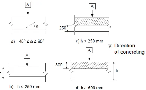
Figure 12: Description of bond conditions Eurocode 2 (2010). ... 19
Figure 13: Anchorage of shear reinforcement (Eurocode 2, 2010). ... 20
Figure 14: Minimum anchorage of reinforcement in flat slabs (Tesoro, 1991). ... 22
Figure 15: Definition of Asl (Eurocode 2, 2010). ... 23
Figure 16: Cracking pattern of slab after failure. ... 25
Figure 17: Example of support zone in waffle slabs (Starosolski, 2003). ... 25
Figure 18: Basic control perimeter. ... 28
Figure 19: Basic control perimeters close to edge or corner (Eurocode 2, 2010). ... 28
Figure 20: Reduced basic control perimeter u1* ... 29
Figure 21: Coefficients recommended in eurocode 2, 2010. ... 29
Figure 22: Slab with enlarged head where lH < 2hH (Eurocode 2, 2010). ... 30
Figure 23: Slab with enlarged head where lH > 2hH (Eurocode 2, 2010). ... 31
Figure 25: Stud considered to resist punching shear. ... 32
Figure 26: Spacing of links (Eurocode 2, 2010). ... 32
Figure 27: Edge beams in waffle slab. ... 35
Figure 28: Division of slab into frames for the method of Cachim (2005). ... 39
Figure 29: Plan of a slab with beams. ... 41
Figure 30: Comparison of costs of materials and formwork and labour per m2 of total area of building for slabs with column heads. ... 44
Figure 31: Total cost of slabs with column heads and columns per m2 of the total area of the building. ... 44
Figure 32: Comparison of costs of materials and formwork and labour per m2 of total area of building for waffle slabs. ... 45
Figure 33: Total cost of waffle slabs and columns per m2 of the total area of the building.46 Figure 34: Comparison of costs of materials and formwork and labour per m2 of total area of building for flat plates. ... 47
Figure 35: Total cost of flat plates and columns per m2 of the total area of the building ... 47
Figure 36: Comparison of costs of materials and formwork and labour per m2 of total area of building for slabs with beams ... 48
Figure 37: Total cost of slabs with beams and columns per m2 of the total area of the building ... 49
Figure 38: Total costs of slabs and columns per m2 of total area of building for span of 7.2m. ... 50
Figure 39: Comparison of costs of materials and formwork and labour per m2 of total area of building for all considered slabs. ... 50
L
IST OF TABLES
Table 1: Percentage of area of reinforcement required for the mid-span design moment. ... 8
Table 2: Bending moment coefficients for square panels supported on four sides with provision for torsion at corners for ly / lx = 1.0... 9
Table 3: Simplified apportionment of bending moment for a flat slab in Eurocode 2 (2010). ... 12
Table 4: k values for calculating rough estimate of internal forces and moments (Cachim, 2005). ... 14
Table 5: Percentage of bending moments (Tesoro, 1991). ... 16
Table 6: Values of k for rectangular loaded areas. ... 27
Table 7: Considered actions ... 35
Table 8: Cost of materials ... 36
Table 9: Price comparison of reinforcement in 100m of beam ... 37
Table 10: Bending moments in considered slabs in direction x for span of 7.2m [kNm]. .. 40
Table 11: Bending moments in considered slabs in direction y for span of 7.2m [kNm]. .. 40
Table 12: Bending moments in the considered slab with beams in direction x for span of 7.2m [kNm/m] ... 41
Table 13: Bending moments in the considered slab with beams in direction y for span of 7.2m [kNm/m] ... 41
Table 14: Axial force in columns from the slab of different types for span of 7.2m [kN].. 42
Table 15: Shear forces in the egde beams ... 42
Table 16: Bending moments in the edge beams. ... 43
List of tables in Appendix B
Table B.1: Slab with column heads – span 7.20m ... 110Table B.3: Slab with column heads – span 8.80m ... 112
Table B.4: Waffle slab - span 7.20m ... 113
Table B.5: Waffle slab - span 8.00m ... 114
Table B.6: Waffle slab - span 8.80m ... 115
Table B.7: Flat plate - span 5.60m ... 116
Table B.8: Flat plate - span 6.40m ... 116
Table B.9: Flat plate - span 7.20m ... 117
Table B.10: Slab with beams – span 7.20m ... 117
Table B.11: Slab with beams – span 6.40m ... 118
Table B.12: Slab with beams – span 5.60m ... 118
List of tables in Appendix C
Table C.1: Cost of columns for the slabs with column heads – span 7.20m... 119Table C.2: Cost of columns for the slabs with column heads – span 8.00m... 119
Table C.3: Cost of columns for the slabs with column heads – span 8.80m... 120
Table C.4: Cost of columns for the slabs with beams – span 5.60m ... 120
Table C.5: Cost of columns for the slabs with beams – span 7.20m ... 121
Table C.6: Cost of columns for the slabs with beams – span 6.40m ... 121
Table C.7: Cost of columns for the flat plates – span 5.60m ... 122
Table C.8: Cost of columns for the flat plates – span 6.40m ... 122
Table C.9: Cost of columns for the flat plates – span 7.20m ... 123
Table C.10: Cost of columns for the waffle slabs – span 7.20m ... 123
Table C.11: Cost of columns for the waffle slabs – span 8.00m ... 124
L
IST OF SYMBOLS
Latin upper case letters
Ac - cross sectional area of concrete
As - cross sectional area of reinforcement
As,min - minimum cross sectional area of reinforcement
As,max - maximum cross sectional area of reinforcement
Asw - cross sectional area of shear reinforcement
Asw.min - maximum cross sectional area of shear reinforcement
Ec,eff - effective modulus of elasticity of concrete
EC2 - Eurocode 2 (2010)
Ecm - secant modulus of elasticity of concrete
Es - design value of modulus of elasticity of reinforcing steel Gk - characteristic permanent action
I - Second moment of area of concrete section M0 - Reference moment
MEd - Design value of the applied internal bending moment
NEd - Design value of the applied axial force
Qk - Characteristic variable action
SLS - Serviceability limit state ULS - Ultimate limit state
VEd - Design value of the applied shear force
VRd - shear resistance of a member with shear reinforcement
Latin lower case letters
b - overall width of a cross-section be - effective width of a cross-section
bt - mean width of a cross-section
cmin - minimum concrete cover
cmin,b - minimum cover due to bond requirement
cmin,dur - minimum cover due to environmental conditions
cnom - nominal concrete cover
d - effective modulus of elasticity of concrete dg - maximum size of aggregate
e - eccentricity
fcd - design value of concrete compressive strength
fck - characteristic compressive cylinder strength of concrete at 28 days
fctm - mean value of axial tensile strength of concrete
fyd - design yield strength of reinforcement
fyk - characteristic yield strength of reinforcement
fywd - design yield of shear reinforcement
k - coefficient
h - height
lb,rqd - basic required anchorage length
lH - distance from face of a column to face of drop panel
s - spacing of stirrups
sr - spacing of shear links in the radial direction
st - spacing of shear links in the tangential direction
u -
u1 - basic control perimeter
u1* - reduced control perimeter
ui - considered perimeter
uout,ef - perimeter where shear reinforcement is no longer required
vEd - design value of the applied shear stress
vRd,c -
design value of the punching shear resistance of a slab without punching shear reinforcement along the control section considered
vRd,max -
design value of the maximum punching shear resistance along the control section considered
z - inner lever arm
Greek letters
ζ - reduction factor/distribution coefficient Ø - diameter of a reinforcing bar
α - angle; coefficient
γc - partial factor for concrete
γs - partial factor for steel
δ - increment/redistribution ratio
μ - reduced moment
ρ1 - reinforcement ratio for longitudinal reinforcement
1. I
NTRODUCTION
The construction industry is constantly looking for more effective solution. Especially in the era of worldwide crisis the approach to economic side of construction is significant. The construction of a slab because of its dimensions and area and form is very important part of the total cost of the building. The main aim of the dissertation is to compare reinforced concrete flooring systems. The comparison focuses on the economic appraisal (evaluation). Simplicity of realization which means lower labour costs and quantity of used materials are two crucial factors when considering economy of construction.
The type of construction is reinforced concrete construction. Method of construction is cast in place. A model of buildings with 6 storeys is under focus of this dissertation. This is the residential building without any special loads. This assumption helps to focus on the essence of considered problem. The plan of storeys of the building is simple and symmetrical. The common spans form 5.6m to 8.8m are taken into consideration. In the dissertation solid slabs spans in two directions with loads distributed uniformly were presented. The angles of considered slabs are right.
1.1. Objectives
The present work has as the main objective to make a comparative analysis of costs between different types of flat slabs and columns supporting them, in order to facilitate the decision of choosing the right slab among many types of flooring systems.
2. T
WO
-
WAY SLAB SYSTEMS
Two-way concrete slabs are classified by load transfer system. The correct thickness is designed on the basis of an economical reinforcement which can be estimated as reinforcement ratio of 0,3 0,9% (Starosolski, 2003). Two-way slabs bend under load in both principal directions therefore there is a necessity to design layers of bars that are perpendicular to each other.Calculating a two-way slab uses the assumption that concrete is isotropic material. In restrained slabs the corners are prevented from lifting. In two-way slabs bending and torsion moments and shear forces are present. The characteristic dead load and imposed loads are approximately the same on the considered and adjacent panels.
2.1. Types of slabs
2.1.1. Flat plates
Flat plates are reinforced concrete slabs of uniform thickness that transfer loads directly to the supporting columns. Flat plate is a popular and well thought of slab mainly for its ease to arrangement the interior. Due to their simple formwork and reinforcing bar arrangement flat plates are quick to construct. They assure the highest level of flexibility in the arrangement of columns and partition walls and need the smallest storey height to provide headspace requirements. Flat plates have high fire resistance due to lack of sharp corners in which the phenomenon of spalling of the concrete may occur. Usually, the spandrel beams at the edges are designed. According to MacGregor (2012) for spans longer than 6.0m, the thickness required for the shear transfer of vertical loads to the columns exceeds that required for flexural strength. As a result, the concrete at the middle of the panel is not used efficiently. In this dissertation a confirmation of this statement is sought.
A possible problem in transferring the shear force may occur at the perimeter of the columns. It may therefore be necessary to increase column sizes or slab thickness or to use shearheads. Shearheads consist of steel I profile placed in the slab height over the column. Albeit using steel beams may seem expensive, it is still profitable when taking into consideration the simple and cheap formwork of such slab. For heavy industrial loads or long spans flat plates are not economical but they are commonly used in residential type of buildings.
2.1.2. Slabs with beams
Two-way slab with beams is used when the loads or spans or both are large and it is more economical to construct such a slab, despite the higher formwork expenditure. Putting it into other words, beams between columns strengthen the slab.
2.1.3. Waffle slabs
Waffle slabs (Figure 3) are constructed by arranging square molds with tapered sides with spaces between them. The concrete is later cast over and between the molds creating a characteristic waffle shape. These slabs are usually constructed solid near columns because there may be a problem with shearing force as in flat plates. Waffle slabs are rather thick and as a result they provide large moment arms for the reinforcing bars. Thanks to molds the weight of the concrete is significantly reduced without substantially changing the moment resistance. The span among ribs is typically less than 1,5m. Note that, near the
columns. This type of slab is also known as a two-way joist system. Waffle slabs are used for spans from 7.5m to 12.0m.
Figure 3: Examples of waffle slabs. Solid heads in waffle slabs
Solid heads in waffle slabs are thicker areas of slab in proximity of columns. Their function is to transmit loads to columns and be the support for ribs and resist shear punching.
The height of solid heads is usually the same as the ribs. However, when large concentrations of loads occurs in the area of columns, thickness of solid heads may be greater. The half of a solid head dimension must be at least 0.15 times the span corresponding measured from the axis to the edge of the column (Figure 4). However, these are often constrained by the geometry of the molds which leads to the larger sizes required (Tesoro, 1991).
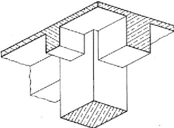
2.1.4. Flat slab
Flat slab (Figure 5) are reinforced concrete slabs with capitals, drop panels, or both. Although the framework is more expensive than for flat plates, the usage of concrete and steel is economical when heavy loads and long spans occur. They are particularly economical for structures where exposed drop panels or column capitals are acceptable. Flat slabs are used for spans from 6.0m to 9.0m.
Figure 5: Flat slab with enlarged column heads and drop panels. Column heads
The column head is the enlargement of the upper section of the column or thicker area of the slab. Currently, its scope has been reduced to industrial type buildings and commercial spaces, due to high overloads that these types of constructions lead (Tesoro, 1991). These elements are designed to resist moments and shear forces in the proximity of columns. Drop panels
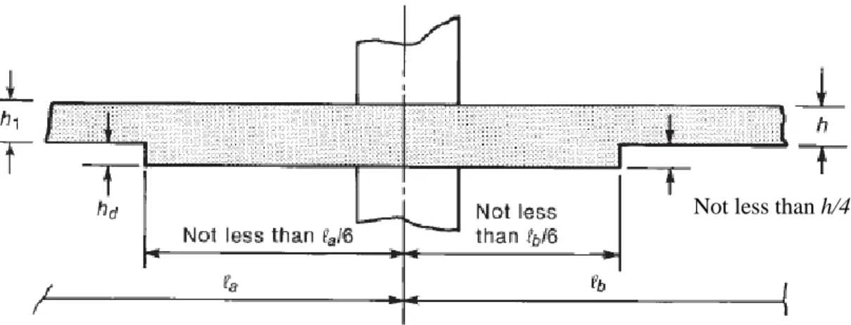
The drop panel stiffens the slab in the region of highest moments hence reduces the deflection. The presence of drop panel reduces the amount of negative-moment flexural reinforcement because effective depth of slab is increased. With the additional slab depth at the column, the area of the critical shear perimeter is increased. Minimum thickness of slab may be reduced by 10% if drop panels are present according to ACI Code Section 13.2.5. The thickness of the drop panel below the slab used in the calculations shall not be taken greater than one-fourth of the distance from the edge of the drop panel to the face of the column or column capital. If the drop panel were deeper than this, it is assumed that the maximum compression stresses would not flow down to the bottom of the drop panel, and thus, the full depth would not be effective, according to ACI Code Section 13.2.7. For economy in form construction, the thickness of the drop, shown as hd in Figure 6 should be
Figure 6: Minimum size of drop panel according to ACI Section 13.2.5.
2.2. Slab thickness
The parameters that determine the thickness of flat slabs are usually the punching shear and deformations.
According to Jiménez Montoya (2001) the thickness of flat slab should not be less than the minimum value of 12cm or 1/32 of the largest span. With respect to waffle slab, the thickness should not be less than the minimum of 15cm or 1/28 of the larger span.
In practice, these minimum values are not recommended, since the lead to deformation problems. The usual minimum thicknesses for flat slabs is 15cm or l/30 and for waffle slabs is 20 cm or l/25 respectively (Jiménez Montoya, 2001).
In order to control deformations Eurocode 2 (2010) in point 7.4.2 limits the span/effective height ratio. According to Eurocode 2 (2010), in the case of flat slabs with span greater than 8.5m, the span/effective height ratio should be multiplied by 8.5/leff (leff in meters). leff
is defined in section 5.3.2.2 (1) of that standard. Regarding the compression area in the case of waffle slab, Eurocode 2 (2010) requires a thickness of topping slab exceeding 1/10 of the clear span between the ribs or 50mm.
3. C
ALCULATION OF
RC
SLABS AND COLUMNS
For the analysis of the slabs the simplified methods was used. For the design, security checks and construction rules, it was considered the current legislation applied in the member countries of the European Committee for Standardization, namely the Eurocodes. In order to make a decision among the use of specific type of slab, in the analysis of the results the price for the necessary resources and the total cost of each slab and columns for each study model should be delivered.
Not until deflection surpasses the obligatory standard, which is unacceptable, the value of a building on the real estate market is not affected. Therefore complying with the European standards in the matter of serviceability limit state is for every slab prerequisite.
3.1. Columns
To minimalize cost the columns have different cross section area on every two storeys. The cross section area of columns was calculated in accordance to EC2. When predimensioning of columns β coefficient which estimates the occurrence of eccentric support reaction with regard to control perimeter was taken into consideration. In Figure 6.21N recommended values of β are given. Values of β differ depend on the position of column in a structure.
3.2. Recommendation for torsion (BS 8110)
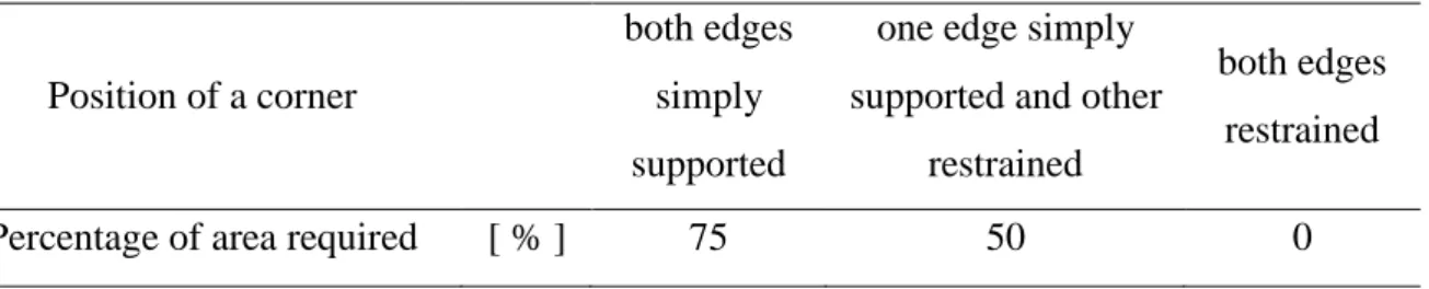
Torsion reinforcement should be provided on a basis of Table 1. It should consist of bars parallel to the edges of the slab and having at least 1/5 of the length of the shorter span. Both the top and bottom reinforcement are required.
Table 1: Percentage of area of reinforcement required for the mid-span design moment.
Position of a corner
both edges simply supported
one edge simply supported and other
restrained
both edges restrained
To estimate bending moments in slab British Standard gives a designer tool of coefficients. In Table 2 the values for considered situations are shown. In the British Standard there are given conditions for the use of equations (1.1) and (1.2), that characteristic dead load and characteristic imposed loads are approximately the same on adjacent panels and the panel being considered. According to BS 8110 in slabs where corners are prevented from lifting, and provision for torsion is made, the maximum design moments per unit width are given by following equations:
(3.1)
(3.2)
where:
, – moment coefficients
– total design ultimate load per unit area
– length of shorter and longer side respectively
The span of adjacent panels is approximately equal the span of the considered panel in the direction perpendicular to the line of the common support.
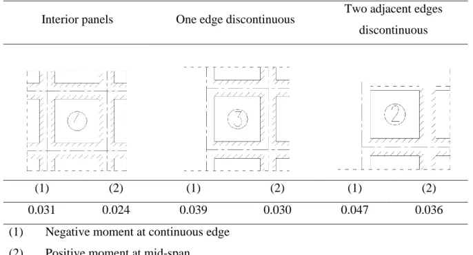
Table 2: Bending moment coefficients for square panels supported on four sides with provision for torsion at corners for ly / lx = 1.0.
Interior panels One edge discontinuous Two adjacent edges discontinuous
(1) (2) (1) (2) (1) (2)
0.031 0.024 0.039 0.030 0.047 0.036
(1) Negative moment at continuous edge (2) Positive moment at mid-span
When pre-dimensioning slab following equation is used:
(3.3)
To estimate the effective depth of a cross-section the . The previous equation is transformed into:
√
(3.4)
3.3. Beams
Beam are present in slabs with beams and as edge beams of other types of slabs. When considering a flat slab there is a question of proportion between beams and columns. The lower storey is analyzed the bigger columns are required to resist vertical force. It demands less labour to design beams which have the same width as the columns. However, on lower storeys the columns width is bigger than one of beams. Figure 7 show this case.
Figure 7: Not desired but practical way of designing beam-column connection. When pre-dimensioning of beams following equation is used. To estimate the effective depth of a cross-section the .
√
For the calculation of flat slabs there are several methods of analysis. When it comes to irregular complex slabs, commercial programs based on the finite element method should be used. They provide ease of use, fast and effective results of the calculation.
However, for situations when slabs are regular sometimes more effective mode is to use simplified methods, which are also easy and quick to use. Taking into account regularity of considered slabs simplified methods were used for the calculation internal forces and moments.
3.4. Equivalent frame analysis
According to Appendix I of Eurocode 2 equivalent frame analysis method consists in decomposing the structure in each of the orthogonal directions – longitudinal and transverse into frames consisting of columns and slab sections ranging between the center lines of adjacent panels. Panel is an area bounded by four adjacent supports. The slab can be analyzed using the methods applicable flat or plane frames. The calculation of the stiffness of the elements may be realized using their gross cross-sections. In the case of vertical loads, the rigidity takes into account the total width of the panels, whereas for horizontal loads must be considered 40% of this value to characterize a greater flexibility of the connections between the pillars and slabs structures flat slabs, when compared with the column/beam joints.
The total load acting in each direction should be analyzed. Thus, every column gets two bending moments (Mx and My) and two axial forces are obtained for each of the orthogonal
directions. For the design of the columns should be considered the two bending moments and the maximum value of the axial force obtained from the two directions (Tesoro, 1991). In every considered frame bending moments distribute themselves within the limits recommended by Eurocode 2 (2010) in accordance with Table 3.
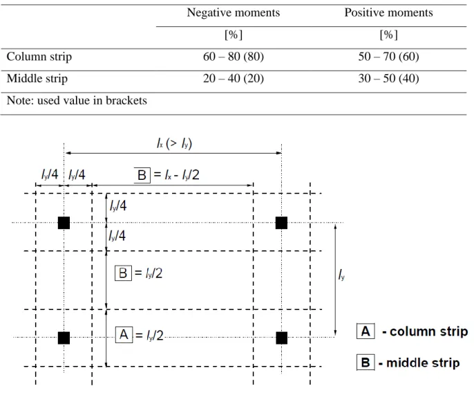
When in slab, drops are wider than one third of span, the column strips may be taken to be the width of drops. The width of middle strips should then be adjusted accordingly.
Table 3: Simplified apportionment of bending moment for a flat slab in Eurocode 2 (2010).
Negative moments Positive moments
[%] [%]
Column strip 60 – 80 (80) 50 – 70 (60)
Middle strip 20 – 40 (20) 30 – 50 (40)
Note: used value in brackets
Figure 9: Division of panels in flat slabs (Eurocode 2, 2010).
If there are not perimeter beams, which are adequately designed for torsion, Eurocode limits moments transferred to edge or corner columns to the moment of resistance of a
(3.6)
– effective width (Figure 10) – effective height
– characteristic value of strength of concrete
According to the Eurocode 2 (2010), the positive moments in the end span should be adjusted.
Figure 10: Effective width - be (Eurocode 2, 2010).
Cachim (2005) suggests the values listed in Table 4, which were derived from the regulation American standard ACI318-77:1983 and the British standard BS8110:1997. These values are valid under the following conditions:
The length of the spans should not differ by more than 20% Actions should be predominantly distributed
The variable load should be less than twice the amount of permanent load There is not redistribution of moments’ values
Table 4: k values for calculating rough estimate of internal forces and moments (Cachim, 2005).
On the supports considered an average of the spans (2) extreme span with continuity, support beam
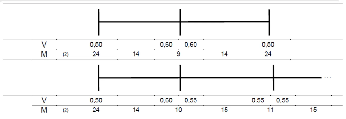
Given the k values presented in
, the bending moments and shear forces can be determined by the following expressions:
(3.7)
(3.8)
From the mentioned simplified method, there is not possible to determine the shear force in slab or lighter efforts in prefabricated fascia. Taking this into account other criteria were introduce for obtaining these values.
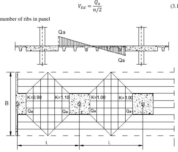
For the determination of shear force in each rib of waffle slab (Figure 11) can be considered the following criteria in accordance with Teroso (1991):
(3.9)
– span
– width of equivalent panel – total load per m2
The shear force which the beams situated outside the solid slab around column should resist is equal to:
(3.10)
– number of ribs in panel
Figure 11: Coefficients to calculate shear force in beams (Tesoro, 1991). For the simplified calculation of bending moments in edge beams, according to Tesoro (1991), the following expressions may be adopted:
(3.11) (3.12) (3.13) (3.14) – span
– width of equivalent panel – linear load of external walls
Values of and are the percentage of positive and negative bending moments, taken from Table 5: . The coefficient that allows to take into consideration the size of the columns has the value of 0.87.
Figure 12: a) Coefficients to determine moments b) Coefficients K (Tesoro, 1991).
Table 5: Percentage of bending moments (Tesoro, 1991).
A M- total M+ total [m] [%] [%] 6.0 38 32 6.5 33 28 7.0 32 27 >7.0 30 25
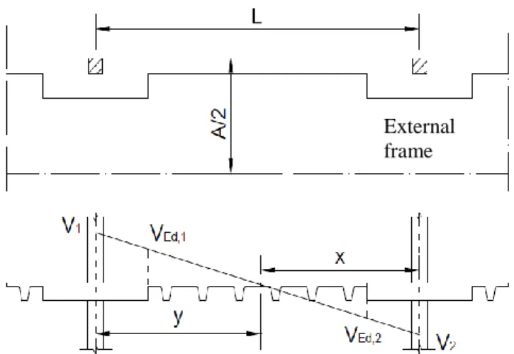
According to Tesoro (1991), the cross-section where the edge beam required to be checked for shear resistance is in proximity of solid heads. For the determination of shear the following practical criteria can be applied, since in practice these beams are symmetrically armed (Figure 13).
(
) (3.15)
(
) (3.16)
where σ is the percentage of the total shear to designate the virtual frame edge beam, which may be obtained from the same table as for moments (Table 5: ).
Figure 13: Shear force in edge beams (Tesoro, 1991).
3.5. General rules of design
3.5.1. Concrete cover
Regarding the cover to reinforcement, Eurocode 2 (2010), establishes the minimum cover
min
c , whose function is to ensure the effective transmission of the forces of adhesion, protection of steel against corrosion and adequate fire resistance, which is determined from the following expression:
c c c c c mm
cmin max min,b; min,dur dur, dur,st dur,add;10 (3.17)
where: b
cmin, - minimum cover due to bond requirement, dur
cmin, - minimum cover due to environmental conditions,
,
dur
c
- additive safety element st
dur
c ,
- reduction of minimum cover for use of stainless steel add
dur
c ,
- reduction of minimum cover for use of additional protection
According to Eurocode 2 the values of cdur, , cdur,st, cdur,add are equal 0mm. Given that the bars are arranged separately, the minimum value of the minimum concrete cover cmin, is given by the diameter of the bar. As for the value of the minimum cover on the environmental conditions cmin,dur, this can be taken from Table 4.4N of Eurocode 2 (2010), taking into account the structural class defined from Table 4.3N of the regulation
External frame
and exposure class. The nominal cover cnom, is determined by the sum of the minimum cover cmin and a margin for calculating tolerances execution cdev. The value recommended by Eurocode 2 (2010), for this last parameter is 10 mm.
dev
nom c c
c min (3.18)
3.5.2. Distance between bars
For the concrete to be placed and compacted satisfactorily for the development of adequate bond, the spacing of bars shall be as follows.
} 20 ; 5 ; max{ d mm mm d g (3.19) where: Ø – diameter of a bar g d - dimension of aggregates
3.5.3. Anchorage of longitudinal reinforcement
To calculate the length of anchorage the following calculation sequence was took into account, according to Eurocode 2.
The design value of the ultimate bond stress is calculated as follows:
ctd
bd f
f 2.2512 (3.20)
where: ctd
f - the design value of concrete tensile strength
1
- coefficient related to the quality of the bond condition and the position of the bar during concreting. When ‘good’ conditions are obtained 11 In other cases 20.7
2
- coefficient related to the diameter of bars: 0
. 1
2
for bars with diameter equal or less than 32mm 100 / ) 132 ( 2
Figure 14: Description of bond conditions Eurocode 2 (2010).
Having regard to Figure 14, the quality of bond conditions were considered "good" in the case of the top reinforcement, when the thickness of the slab is below 250mm. Anchorage for the bottom reinforcement of the ribs were also considered as "good". The basic required anchorage length of a straight bar:
(3.21) where:
sd
- the design stress at the position from where the anchorage is measured from bd
l - the design anchorage length:
(3.22) Where coefficients 1,2,3,4,5are given in Table 8.2 of Eurocode 2 (2010). The minimum anchorage length for anchorages in tension is shown by the equation (1.19). The minimum anchorage length for anchorages in compression is shown by the equation (1.20).
(3.23) (3.24)
3.5.4. Anchorage of shear reinforcement
A bar should be provided inside a hook or bend. Type of anchorage of shear reinforcement is shown in the Figure 15.
Figure 15: Anchorage of shear reinforcement (Eurocode 2, 2010).
3.6. Ultimate limit states
According to Eurocode 0 (2009), ultimate limit states refer to the safety of people and or safety of the structure. In light of this, the verifications of the ultimate limit states were made to bending, shear and punching.
3.6.1. Bending
Calculation of reinforcement
For the design of bending reinforcement simplified expressions were used for rectangular sections subjected to simple bending, based on the parabola-rectangle diagram for concrete. (3.25) √ (3.26) (3.27) where:
– coefficient – design strength of concrete
– applied bending moment – design strength of steel
For the calculation of the lower reinforcement of waffle slab, the ribs are regarded as T-beams, in which initially the calculated position of the neutral axis in order to verify that the height of the compression zone was lower than the height of the flange.
With regard to minimum and maximum area of bending reinforcement, Eurocode 2 (2010), recommends the value given by the following expression:
(3.28)
(3.29) where:
– average width of bending zone – characteristic mean value of tensile strength – cross-section of concrete – characteristic value of strength of steel
In zones of positive moments where crack control is required, minimum amount of bonded reinforcement is required to control cracking in areas where tension is expected. The required minimum areas of reinforcement may be calculated as follows. In profiled cross sections like T-beam, minimum reinforcement should be determined for the individual parts of section according to Eurocode 2 (2010).
(3.30)
where:
– minimum area of reinforcing steel within the tensile zone – area of concrete within tensile zone
– absolute value of the maximum stress permitted in the reinforcement immediately after formation of the crack
– mean value of the tensile strength of the concrete effective at the time when the
cracks may first be expected to occur
- is the coefficient which allows for the effect of non-uniform self-equilibrating stresses, which lead to a reduction of restraint forces
- is a coefficient which takes account of the stress distribution within the section immediately prior to cracking and of the change of the lever arm
Detailing of reinforcement
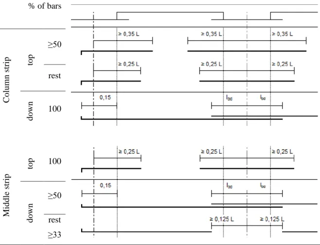
When detailing of reinforcement in flat slabs, in case of analyzing using simplified methods, principles shown in Figure 16 should be used.
% of bars C olum n st rip top ≥50 rest down 100 Mi ddle strip top 100 down ≥50 rest ≥33
Figure 16: Minimum anchorage of reinforcement in flat slabs (Tesoro, 1991). Minimum areas of reinforcement are given in order to prevent a brittle failure, wide cracks and also to resist forces arising from restrained actions (Eurocode 2, 2010).
3.6.2. Shear force
According to point 6.2.1 (4) of Eurocode 2 (2010) the minimum shear reinforcement may be omitted in members such as slabs. In waffle slabs verification of shear force in beams should be checked near solid capitals.
If there is no need to use reinforcement
If there is a need to use reinforcement meeting condition
where:
- design value of the applied shear force
- design shear resistance of the member without shear reinforcement - shear resistance of a member with shear reinforcement
Design shear resistance of the member without shear reinforcement
The value of design resistance of the member without shear reinforcement may be calculated as follows: {[ ] ( ) } (3.31) where: - is in MPa { √ }, d is in mm { }
- is the area of the tensile reinforcement, which extends beyond the
section considered (Figure 17)
Figure 17: Definition of Asl (Eurocode 2, 2010).
- is the smallest width of the cross-section in the tensile area in mm
- is the axial force in the cross-section due to loading or prestressing in N
- is the area of concrete cross section in mm2
Calculation of shear reinforcement
When calculate shear reinforcement Eurocode 2 (2010) gives the limiting values of between and 2.5. For members with vertical shear reinforcement, the shear resistance,
VRd is the smaller value of:
( ) (3.32) where:
– coefficient taking account of the state of the stress in the compression chord
– minimum width between tension and compression chords
– inner lever arm, the approximate value z = 0,9d may normally be used - strength reduction factor for concrete cracked in shear, [
]
Taking this into account, we calculated the shear reinforcement from the expression:
(3.33)
where:
– area of the transverse section of steel
– spacing of stirrups
- design yield strength of the shear reinforcement
Verification of following expression is required by Eurocode 2 (2010).
√
(3.34)
where:
– area of the transverse section of steel
– spacing of stirrups – width of element
In zones of the ribs of waffle slab where shear reinforcement is not required, the minimal reinforcement should be introduced.
3.6.3. Shear punching
Punching shear can result from a concentrated load or reaction acting on a relatively small area, called the loaded area Aload of a slab (Eurocode 2, 2010).This type of failure is dangerous, as manifested abruptly without prior notice. A place where slab has a contact which column is a crucial in every type of flat slab because in this place maximum moments and maximum shear force may be found. In waffle slabs a zone where slab is supported by a column is usually a massive part of the slab with the height of the ribs (Figure 19). It is recommended to avoid placement punching reinforcement in vicinity of the majority of columns (Tesoro, 1991). To reduce problems connected to punching shear, increased height of the slab can be used as well as increased size of the columns or designing column heads. In the Figure 18 cracking pattern of slab after shear punching failure was shown.
Figure 18: Cracking pattern of slab after failure.
According to Eurocode 2 (2010) the verification of punching resistance consists of checking the shear resistance at the face of the column and at the basic control perimeter
u1. The basic control perimeter u1 may normally be taken to be at a distance of double effective depth from the face of column which is a loaded area in this case. If shear reinforcement is required a further perimeter uout or uout,ef should be found where shear reinforcement is no longer required.
For verification of punching shear resistance according to Eurocode 2 (2010), the following checks should be provided:
at the column perimeter
If punching shear reinforcement is not necessary If there is a need to use reinforcement
where:
- design value of the applied shear stress
- design value of the punching shear resistance of a slab without punching shear
reinforcement along the control section considered
- design value of the maximum punching shear resistance along the control
section considered
Design value of the applied shear stress
Punching shear stress, when the support reaction is eccentric should be taken as:
(3.35) where:
– coefficient connected with eccentricity of support reaction
– applied shear force
– length of the control perimeter being considered
- effective depth of the slab is taken as constant as follows:
(3.36)
where:
β coefficient in different cases Internal columns (3.37) where:
- coefficient dependent on the ratio between the column dimensions : its value is a function of the proportions of the unbalanced moment transmitted by uneven shear and by bending and torsion (see Table 6: )
Table 6: Values of k for rectangular loaded areas.
≤ 0.5 1.0 2.0 ≥ 3.0
0.45 0.60 0.70 0.80
– length of the basic control perimeter
- corresponds to a distribution of shear and is a function of the basic control perimeter
(3.38)
where:
- column dimension parallel to the eccentricity of the load - column dimension perpendicular to the eccentricity of the load
For an internal rectangular column where the loading is eccentric to both axes, the following approximate expression for β may be used:
√( ) ( ) (3.39)
where:
and are the eccentricities along y and z axes respectively
Figure 20: Basic control perimeter. Edge columns
According to Eurocode 2 (2010) for edge column connections, where the eccentricity perpendicular to the slab edge (resulting from a moment about an axis parallel to the slab edge) is toward the interior and there is no eccentricity parallel to the edge, the punching force may be considered to be uniformly distributed along the control perimeter u1* as shown in Figure 22.
Figure 21: Basic control perimeters close to edge or corner (Eurocode 2, 2010). Corner columns
According to Eurocode 2 (2010), for corner column connections, where the eccentricity is toward the interior of the slab, it is assumed that the punching force is uniformly distributed along the reduced control perimeter u1*, as defined in Figure 22. The β-value
may then be considered as:
Figure 22: Reduced basic control perimeter u1*
Figure 23: Coefficients recommended in eurocode 2, 2010.
The design punching shear resistance of slabs without shear reinforcement
The design punching shear resistance of slabs without shear reinforcement may be calculated as follows: { } (3.41) where: - is in MPa { √ }, d is in mm {√ }
- relate to the bonded tension steel in y- and z- directions respectively. They
should be calculated as mean values taking into account a slab width equal to the column width plus 3d each side
- is the smallest width of the cross-section in the tensile area in mm
is in MPa
- normal concrete stresses in the critical section in y- and z- directions in MPa,
positive if compression
Control perimeters
In the case when the column head dimensions meet condition , verifying the shear punching stresses should be performed in the control perimeter outside the capital.
Figure 24: Slab with enlarged head where lH < 2hH (Eurocode 2, 2010).
For the columns considered in this dissertation, which are quadratic, the value may be taken as:
(3.42)
where:
- effective depth of the column head or slab – dimension of column side
– see Figure 24
In the case when the column head dimensions meet condition (Figure 25), verifying the shear punching stresses should be performed in control sections both within the head and in the slab.
Figure 25: Slab with enlarged head where lH > 2hH (Eurocode 2, 2010).
Calculation of punching shear reinforcement
To find a necessary shear reinforcement a following equation may be used:
(3.43)
where:
- area of one perimeter of shear reinforcement around the column in mm2
- radial spacing of perimeters of shear reinforcement in mm
- effective design strength of the punching shear reinforcement in MPa
(3.44)
- angle between the shear reinforcement and the plane of the slab
- effective depth of the slab taken as average between orthogonal directions
The outermost perimeter of shear reinforcement should be placed at a distance not greater than 1.5d within uout according to Eurocode 2 (2010) (Figure 26).
(3.45)
Figure 27: Stud considered to resist punching shear.
According to Eurocode 2 (2010), punching shear reinforcement should be located in harmony with Figure 28. Punching shear reinforcement must be constructed with at least two perimeters of shear reinforcement. The spacing of the link leg perimeters should not exceed 0.75d. The distance between the face of a support and the nearest shear reinforcement taken into account in the design should not exceed d/2.
The area link leg should not be lesser than: √ (3.46) where:
– spacing of shear links in the radial direction - spacing of shear links in the tangential direction Punching shear resistance adjacent to the column.
(3.47)
where:
– for an interior column = length of column periphery in mm for an edge column in mm for a corner column in mm – column dimensions
[
]
3.7. Serviceability limit state
The height of slabs were assumed to avoid deflection problems in normal circumstances and as follows avoid necessity of calculation them. To avoid it the span/depth ratio of every type and span of considered slabs lies in the limits proposed by Eurocode 2 (2010). Calculation of crack widths was not conducted.
4. M
ODELS OF STUDY
For comparison of the slabs simplified methods were conducted. To find bending moments occurring in slabs, method of Cachim (2005) where used. This method can be used for at least two spans of similar dimensions. The structure were divided into frames in both orthogonal directions as shown in Figure 30. The bending moment values repeat themselves in every internal frame and external frame respectively in both directions.
In the waffle slabs and slab with enlargement column heads, the dead load is not uniform along the span, as areas along the columns have an higher weight than the rest of the range. With this in mind, an average load along the span was calculated, in order to use the method described by Cachim (2005), for the approximate calculation of the internal forces.
4.1. Materials
In the project concrete of class C30/37 was used. Exposure class related to environmental conditions in accordance with EN 206-1, was chosen as XC1 – concrete inside buildings with low air humidity. Reinforcement was made from A500 NR SD steel.
4.2. Actions
To determine dimensions of structural members knowledge of occurring loads and their sources is inevitable. Actions taken into consideration were shown in Table 7: .
To represent floor and ceilings weight and HVAC systems without self-weight of structure the fallowing characteristic value of permanent actions was applied. Dead load is serious factor for calculating a slab. It is directly connected with thickness of slab which is calculated from Table 7.4N [EC1]. Presence of drop panels or column capitals increases dead load of the slab. In the waffle slab dead load is decreased by application of molds. A characteristic value of imposed loads of typical for residential dwellings was applied in accordance with Eurocode 1 (2009) for category A. Load from wind is not taken into consideration for being considered insubstantial for the structure. Snow does not have a great influence on the structure in Portuguese climate. Considerable majority of Portugal
has very low characteristic value of snow load of up to in minor areas.
Table 7: Considered actions
Permanent actions
Dead load (reinforced concrete) 25.0 kN/m3
Uniformly imposed 5.0 kN/m2
External wall 9.5 kN/m
Variable actions Uniformly imposed 2,0 kN/m2
4.3. Edge beams
Dimensions of edge beams differ depending on the dimensions of molds in waffle slab and for other types of flat slabs, the dimensions of edge and corner columns and thickness of the external wall it may be hidden in. A spandrel beam which is another name for edge beam is shown in Figure 29.
Figure 29: Edge beams in waffle slab.
4.4. Columns
In the considered model of a building different dimensions of columns are used because. It depends on the position of the column. The positions are as follow: internal, edge and corner. The dimensions of columns change every 2 storeys to obtain more economical values. The percentage of steel in the column, the reinforcement ratio, is taken as 2%. The mean value of steel weight for m3 of concrete is assumed as 150kg. The dimensions of
b
columns can be found in Appendix A.1 – A.4 and the cost of columns can be found in the Appendix C.
4.5. Cost of materials, formwork and labour
The prices used in the calculations of cost of resources are presented in Table 8. The prices are valid for construction industry in Portugal.
Table 8: Cost of materials Concrete C30/37
price [euro/m3]
77.5 Steel A500 NR SD
diameter price area
[mm] [euro/kg] [cm2] 6 0.85 0.28 8 0.83 0.50 10 0.80 0.79 12 0.78 1.13 16 0.77 2.01 20 0.77 3.14 25 0.79 3.85
To verify what is the difference between applying two different solutions of reinforcement a simple model was considered. When building 100m of columns or beams with required area of reinforcement of 12cm2 using 6 bars of diameter of 16mm instead of only 4 bars of diameter of 20mm we can safe 30.82€ on steel (Table 9: ). But on the other hand fewer bars in the cross-section mean less labor and the same effects obtained faster and with the less workload for employees. Every day of construction, only in terms of renting unnecessary tools, costs significant amount of money. The amount of 30.82 euro seem to be very little sum of money in this case.
Table 9: Price comparison of reinforcement in 100m of beam Quantity of bars in cross-section Diameter of bar Area of reinforcement Weight of 1m Price of steel in 100m beam [mm] [cm2] [kg] [euro] 4 20 12.56 9.88 760.76 6 16 12.06 9.48 729.96
5. A
NALYSIS OF RESULTS
In this chapter the comparison among various types of flat slabs is presented. The waffle slabs and the slabs with column heads are considered in spans between 7.2m, 8.0m and
8.8m The flat plates and the slabs with beams comparison is provided for spans between 5.6m and 7.2m also with the graduation of 0.8m. The comparison is made to emerge the
most economical solution for the range of spans considered.
The comparison of cost of columns for buildings with different slab systems is presented in this chapter. The cost is estimated per m2 of total area of the building. This means that the area of ground floor and the area of six upper storeys were summed up to calculate the total area.
In Appendix A.1 a complete example of calculation of structural members for waffle slab with grid of columns with span of 7.2m, applied forces and moments are presented,. The adequate calculation for the same grid of columns were made for the slab with column heads in Appendix A.2, the flat plate in Appendix A.3 and the slab with beams in Appendix A.4.
In Appendix B tables of costs for each slab of different systems were presented with division of materials, labour force and formwork.
In Appendix C tables of costs of columns for each slab of different systems were presented.
5.1. Internal forces and bending moments
For comparison of internal forces and bending moments in this chapter the representative model with a span of 7.2m among the grid of columns was chosen as the span, which each of analyzed types of slabs has.
For a better understanding of the following tables in the Figure 30 the division of a slab into frames was presented and in the Figure 31 plan of the slab with beams was presented with the considered cross-sections.
The divisions of the gateways and the tracks were made according to Figure 3.3 and Figure 3.4.
For comparison of the flat slabs simplified methods were conducted. These methods are not very precise compared to the finite element method, which leads to more realistic values, since it takes into account the variations of loads and allows to obtain a better estimation of deformation. The simplified method is precise enough to compare the slabs and obtain relevant conclusions.
To find bending moments occurring in slabs, method of Cachim (2005) was used. This method can be applied for at least two spans of similar dimensions. The structure was divided into frames in both orthogonal directions as shown in Figure 30. The values of bending moment repeat themselves in every internal frame and external frame respectively in both directions.
Figure 30: Division of slab into frames for the method of Cachim (2005).
The values in Table 10 and Table 11: were calculated using method of professor Cachim (2005). The conclusion may be made that the values of the bending moments among different types of slabs are similar to each other. This is due to the fact that the applied loads are similar. The difference in loading lays in difference among dead load of specific type of the slab. The simplified method of finding bending moments is slabs proposed by professor Cachim (2005) requires knowing the uniformly distributed load. To calculate the uniformly distributed load on every type of slabs the approximation of dead load value should be made. For example when calculating dead load of slab with column heads, there
A External Support B Internal Support C Internal Support A External Support B Internal Support External Span 1 Exte rn al Sp an 1 External frame Internal frame External frame In te rn al fra m e In te rn al fra m e In te rn al fra m e Exte rn al fra m e Exte rn al fra m e Fra m es in x dir ect io n Frames in y direction A External Support B Internal Support Exte rn al Sp an 1 Internal Span 2 Internal Span 2 External Span 1 V3 V1 V2 V2 V1 V3
is the area of slab with normal height and the area of drop panels with bigger height and different rigidity but there is no mode to take it into consideration, the approximation should be done.
Table 10: Bending moments in considered slabs in direction x for span of 7.2m [kNm]. Type of slab Strip External
support A External span 1 Internal support B Internal span 2 Internal support C Slab with column heads Column 188.66 277.22 452.79 258.74 411.62 Middle 80.85 184.81 194.05 172.49 176.41
Waffle slab Column
189.29 278.14 454.29 259.59 412.99
Middle 81.12 185.42 194.70 173.06 177.00
Flat plate Column
227.42 334.16 545.80 311.89 496.18
Middle 97.46 222.78 233.91 207.92 212.65
Table 11: Bending moments in considered slabs in direction y for span of 7.2m [kNm].
Type of slab Strip External support A External span 1 Internal support B Slab with column heads Column 188.66 277.22 503.10 Middle 80.85 184.81 215.61
Waffle slab Column
189.29 278.14 504.77
Middle 81.12 185.42 216.33
Flat plate Column
227.42 334.16 606.45
Figure 31: Plan of a slab with beams.
The slabs with beams were designed using British standard BS 8110:1997. For the different types of supports there are determined coefficients to calculate the bending moments. The plan of a considered slab with beams is shown in Figure 31. Table 12: and Table 13: show the values of bending moments in the slab of span of 7.2m.
Table 12: Bending moments in the considered slab with beams in direction x for span of 7.2m [kNm/m]
Cross section
MEd,1-1 MEd,1-2 MEd,2-2 MEd,2-3 MEd,3-3
External support External mid-span Internal support Internal mid-span Internal support A-A 0.00 38.28 -45.72 31.90 -41.47
Table 13: Bending moments in the considered slab with beams in direction y for span of 7.2m [kNm/m]
Cross section
MEd,a-a MEd,a-b MEd,b-b
External support External mid-span Internal support C-C 0.00 38.28 -45.72 D-D 0.00 31.90 -41.47
In Table 14 axial forces transmitted from a single slab of different types to the columns in different position as internal, edge and corner are shown. The values are similar in every case because the applied load is the same.
Table 14: Axial force in columns from the slab of different types for span of 7.2m [kN]
In Table 15: shear forces in the edge beams are presented. The values for waffle slab and
slab with column heads are similar, and the values for the flat slab are bigger.
Table 15: Shear forces in the egde beams
Beam Slab Left support Right support
V1
Flat plate 60.99 73.18
Waffle slab 51.91 62.29
Slab with column heads 51.76 62.11
V2
Flat plate 67.09 67.09
Waffle slab 57.10 57.10
Slab with column heads 56.94 56.94
V3
Flat plate 60.99 73.18
Waffle slab 51.91 62.29
Slab with column heads 51.76 62.11
In Table 16 bending moments in the edge beams are presented. The values for waffle slab Type of slab
Internal column Edge column Corner column Slab with column heads
894.24 539.46 315.90
Waffle slab
901.37 543.02 317.68
Slab with beams
1222.72 744.27 398.71
Flat plate
Table 16: Bending moments in the edge beams.
Beam Slab Left support Mid-span Right support
V1
Flat plate 31.87 33.19 55.76
Waffle slab 27.60 28.75 48.30
Slab with column heads 27.53 28.68 48.18
V2
Flat plate 47.80 26.55 47.80
Waffle slab 41.40 23.00 41.40
Slab with column heads 41.29 22.94 41.29
V3
Flat plate 31.87 33.19 55.76
Waffle slab 27.60 28.75 48.30
Slab with column heads 27.53 28.68 48.18
5.2. Comparison of costs
A comparative cost analysis performed in this thesis encompasses four types of flat slabs, waffle slab, slab with column heads, slab with beams and flat plate as well as the columns which are required to support these slabs.
5.2.1. Cost structure of slabs with column heads
The price of concrete required per m2 for slabs with column heads of spans between 7.2m and 8.8m considered every 0.8m are very similar. The cost of steel used in discussed slab grows with the span and reaches value of 27.23€/m2 for span of 8.8m. The top reinforcement of the slab with column heads was increased to satisfy the good practice of not using shear punching reinforcement in proximity of every column both within the column heads and in the slab. This solution helped to avoid placing studs or bended bars used as shear punching reinforcement in the proximity of internal columns but simultaneously increased the labour which must be spent for placing longitudinal reinforcement above the column heads in the top part of the slab. The formwork and labour stay at the same level for different spans and falls within the price ambit of 18.03€/m2 to 19.82€/m2. The cost structure divided into different resources of those cost is presented in
the Figure 32. The cost of slabs and columns supporting them may be seen in the Figure 33.
Figure 32: Comparison of costs of materials and formwork and labour per m2 of total area of building for slabs with column heads.
Figure 33: Total cost of slabs with column heads and columns per m2 of the total area of the building. 0 5 10 15 20 25 30
concrete steel formwork and
labour €/m 2 7.2m 8.0m 8.8m 0 10 20 30 40 50 60 70 7.2m 8.0m 8.8m €/m 2 columns