Department of Information Science and Technology
Co-evolution of Morphology and
Controller for a Robot
Ivo Manuel Caeiro da Silva
A Dissertation presented in partial fulfillment of the Requirements
for the Degree of
Master in Computer Engineering
Supervisor
Assitant Prof. Dr. Sancho Moura Oliveira, assistant professor
ISCTE-IUL
Co-Supervisor
Assistant Prof. Dr. Anders Lyhne Christensen, assistant professor
ISCTE-IUL
Os algoritmos genéticos são inspirados pelo processo de seleção natural que existe na natureza. Este processo leva espécies a evoluir e adaptar-se ao meio ambiente envolvente, com as espécies mais aptas reproduzindo, levando a que novas gerações possam tirar um melhor proveito do ambiente que as rodeia. Este tipo de processo pode ser utilizado na robótica evolucionária para evoluir controladores capazes de resolver tarefas de forma a evoluir morfologias para uma finalidade específica, tais como andar, nadar, agarrar objetos, entre outros.
Garras robóticas são utilizadas na maioria das fábricas, assim como noutros locais de trabalho tais como hospitais e laboratórios. Podem ser utilizadas em tarefas como agarrar/mover objetos, pintura, cirurgias, entre outros usos. São, portanto, um caso de estudo com várias possibilidades que se prestam à evolução de mor-fologias através de algoritmos genéticos.
Nesta dissertação, exploramos a geração de morfologia através de algoritmos genéti-cos. Utilizando garras como o nosso caso de estudo, conseguimos gerar garras capazes de agarrar e levantar um objeto. Para evoluir essas garras, criamos um ambiente simulado onde cada garra seguiu um script com instruções para agarrar o objeto e, em seguida, mover para cima. No total, 120 garras diferentes foram geradas nestas experiências. Dessas garras geradas 120, 28% foram capazes de capturar e levantar um objeto com êxito.
Após a conclusão do processo de avaliação, experimentamos as garras em cinco cenários diferentes para testar a sua robustez. Nesses cenários, as condições iniciais em que os objetos começam eram diferentes das do processo de avaliação.
Genetic algorithms are inspired by the process of natural selection that exists in nature. This process is what leads species to evolve and adapt to their surround-ings, with the fittest species reproducing, leading to new generations that can take advantage of their surroundings better than before. This type of process can be used in evolutionary robotics to achieve controllers that are able to solve specific tasks to evolve morphologies for a specific purpose such as to walk, swim, grasp objects, among others.
Robotic grippers are used in most factories nowadays, as well as in other workplaces such as hospitals and laboratories. They are used in tasks such as grabbing/moving objects, painting, surgeries, among many other uses. Grippers are therefore a case study with several possibilities that lend themselves to evolving morphologies through genetic algorithms.
In this dissertation, we explore morphology generation through genetic algorithms. Using grippers as our case study, we were able to generate grippers capable of grabbing and lifting an object. To evolve these grippers, we created a simulated environment where grippers followed a script with instructions to grab the object and then move up. In total 120 different grippers were generated in these exper-iments. Out of those 120 generated grippers, 28% were able to grab and lift an object successfully.
After the evaluation process was completed, we experimented with the grippers in five different scenarios to test their robustness. In these scenarios, the object’s starting conditions were different from those in the evaluation process.
I would like to start by thanking my supervisor Professor Sancho Oliveira for guiding me through the process of building this thesis. His opinions and feedback were crucial in moving the thesis in the right direction.
I would also like to thank my co-supervisor Professor Anders Christensen whose feedback led to a more coherent and complete thesis.
Thanks to João Sousa from Vitruvius FabLab for helping with building and mod-eling the 3D pieces we use when generating the final gripper.
Thanks to my parents, Mário Silva and Cidália Silva, whose support and love made me carry on and not give up, even in the hardest moments. Not understanding the theme of this thesis didn’t stop both of you from trying to help me along the way, and for that I am thankful.
Thanks to my friends for being there, especially Diogo Vicente and Nuno Coelho, whose support, words of encouragement, and long conversations about everything helped me come this far.
Resumo v
Abstract vii
Acknowledgements ix
List of Figures xiii
1 Introduction 1
1.1 Objectives . . . 3
1.2 Research Questions . . . 4
1.3 Structure of the Dissertation . . . 5
2 State of the Art 7 2.1 Evolving Controllers and Morphologies . . . 7
2.1.1 Automatic generation . . . 8
2.1.2 Automatic design and Manufacture . . . 9
2.2 Genotypes and Phenotypes Generation . . . 10
2.2.1 NeuroEvolution of Augmenting Topologies . . . 11
2.3 Grippers . . . 12
2.3.1 Haptic Identification of Objects . . . 14
2.3.2 Piezoelectric Grippers . . . 15
2.3.3 Minimally Invasive Surgery with Grippers . . . 16
3 Evolution, Simulation & Prototyping 19 3.1 Evolution . . . 19 3.2 Simulator . . . 23 3.3 Prototyping . . . 30 4 Results 33 4.1 General Results . . . 37 4.2 Capsule Results . . . 42 4.3 Cylinder Results . . . 44 4.4 Rectangle Results . . . 46 4.5 Sphere Results . . . 48
5 Robustness Test of Evolved Morphologies 51
6 Conclusions 65
Appendices 75
A Hands evaluated to grab capsules: Fitness Graph 75
B Hands evaluated to grab cylinders: Fitness Graph 77
C Hands evaluated to grab rectangles: Fitness Graph 79
D Hands evaluated to grab spheres: Fitness Graph 81
E Sequence of a successful hand 83
F Example of an unsuccessful hand 85
2.1 Automatic Generation evolved solutions . . . 9
2.2 Automatic Design and Manufacture evolved solutions . . . 10
2.3 Harvester gripper . . . 14
2.4 Piezoelectric gripper example . . . 14
2.5 Gripper that identifies objects haptically . . . 15
2.6 Minimal invasive gripper . . . 17
3.1 Representation of the first generated hand . . . 21
3.2 Properties of a generated block . . . 21
3.3 Graphic breakdown of the simulated environment . . . 26
3.4 Fin and Servo pieces . . . 31
3.5 Generated block from the simulation . . . 31
3.6 Final generated piece . . . 31
3.7 Gripper assembled . . . 32
4.1 Graphic demonstration of the four samples . . . 34
4.2 Evaluations results breakdown. . . 38
4.3 Hands that grabbed the object in all samples . . . 38
4.4 Hands that grabbed the object in half of the samples . . . 39
4.5 Hands that grabbed the object in less than half of the samples . . . 40
4.6 Average number of blocks by object size. . . 40
4.7 Best hand for large capsules . . . 42
4.8 Best hand for medium capsules . . . 43
4.9 Best hand for small capsules . . . 43
4.10 Best hand for large cylinders . . . 44
4.11 Best hand for medium cylinders . . . 45
4.12 Best hand for small cylinders . . . 45
4.13 Best hand for large rectangles . . . 46
4.14 Best hand for medium rectangles . . . 47
4.15 Best hand for small rectangles . . . 47
4.16 Best hand for large spheres . . . 48
4.17 Best hand for medium spheres . . . 49
4.18 Best hand for small spheres . . . 49
5.1 Medium cylinder pattern . . . 53
5.3 Capsule that can grab and lift large cylinders. . . 55
5.4 Rectangle that can grab and lift large spheres . . . 56
5.5 Large capsule size increment results . . . 59
5.6 Large rectangle size increment results . . . 60
5.7 Medium cylinder size increment results . . . 61
5.8 Medium rectangle size increment results . . . 61
A.1 Fitness Graph for hands evolved to grab and lift large capsules . . . 75
A.2 Fitness Graph for hands evolved to grab and lift medium capsules . 76 A.3 Fitness Graph for hands evolved to grab and lift small capsules . . 76
B.1 Fitness Graph for hands evolved to grab and lift large cylinders . . 77
B.2 Fitness Graph for hands evolved to grab and lift medium cylinders . 78 B.3 Fitness Graph for hands evolved to grab and lift small cylinders . . 78
C.1 Fitness Graph for hands evolved to grab and lift large rectangles . . 79
C.2 Fitness Graph for hands evolved to grab and lift medium rectangles 80 C.3 Fitness Graph for hands evolved to grab and lift small rectangles . . 80
D.1 Fitness Graph for hands evolved to grab and lift large spheres . . . 81
D.2 Fitness Graph for hands evolved to grab and lift medium spheres . 82 D.3 Fitness Graph for hands evolved to grab and lift small spheres . . . 82
E.1 Sequence of a successful hand . . . 84
Introduction
Industrial robots are typically used in factories. They have been replacing humans for the last decades in completing repetitive tasks that can be automated. What makes these robots valuable in the workplace is the speed and precision with which they are able to perform tasks and the reduction of costs.
These robots are present in different industries and while they have different pur-poses, their core remains the same; the robot must be programmable and must be able to move or rotate in at least two axis. Robotic arms are programmed to fit the designated task, and the same happens to the robotic arms degrees of freedom. Depending on the task, the arm will have more or less freedom of movement along the three axis (x, y, z), and the rotation along the axis (yaw, pitch, roll).
These robotic arms are versatile, and as such they can be found in various factories from different industries. A common use for robotic arms is in automotive factories, where they are used in very different ways. In this industry, the robotic arm is used to weld, assemble and paint car parts.
Robotic arms have at their ends a robot part designated as an end-effector. This piece can be modified to adapt to the task. For example, a robotic arm used to weld needs to have a welding piece attached at its end to perform the task, while a robotic arm whose task is to paint parts, needs a tool that can shoot ink, for example a spray gun to paint. For tasks directed at grabbing and moving objects,
a gripper is a more fitting tool. The grippers are usually used to move objects from one point to another, or to hold the object still while another tool, or worker works on it.
Creating a gripper is a complex task, which is why such task can be split into different categories for instance, heavy/light objects, small/big objects, or even long/short objects for the gripper to grab. By splitting the possibilities into single objects for the gripper to grab, gripper creation becomes a more manageable task. By doing this, specific grippers are created to grab specific objects.
However, nature’s own evolutionary process led to the generation of a versatile gripper known as the human hand. This gripper, despite being versatile, cannot grab objects as easily as a robotic gripper built for that purpose. Our hands required years of training to grab objects, and some objects we may never be able to grab due to our hands properties, or the objects surface properties.
Unlike our hand that can only grab objects by grip and force, robotic grippers can be divided into four categories, depending on which technique they use to grab objects:
• Impactive, one of the most common types of grippers that use the same techniques as our hands to grab objects (force and grip);
• Ingressive, these types of grippers use pins or needles to penetrate the object in order to grab it;
• Astrictive, which use suction techniques (vacuum, magnetism, electro adhe-sion) to grab the object;
• Contigutive, these ones require a type of glue to grab the object.
The purpose of this dissertation is to evolve a gripper capable of grabbing ob-jects independent of their size or rotation, and for that we chose to simulate the impactive type of gripper to conduct our experiments in evolving grippers.
The impactive gripper is one of the most basic types of gripper, and one that emulates our hands to some extent in the actions it takes to grab objects. This type of gripper applies an amount of force to grab an object, unlike for example, the ingressive gripper that uses pins or needles for the same task.
To run these experiments in order to evolve grippers, we used genetic algorithms. This type of algorithms were first introduced by Holland (1962) and are based around biological processes observed in nature, as such, it makes sense to try and experiment with them to evolve the impactive gripper’s morphology so that we can get solutions that followed the same principle as our own hands.
Genetic algorithms are commonly used in evolving morphologies and controllers. With genetic algorithms the simulation starts with a population of randomly gen-erated individuals, with each individual trying to complete the task and being attributed fitness points depending on how well it performed the task. The best individuals are then chosen to start a new population by being cloned. Those clones have a chance to suffer mutations. These mutations allow for different so-lutions to emerge within the simulation. This process repeats until the number of generations is reached.
Due to their versatility and accessibility, impactive grippers were chosen to conduct our study on evolving morphologies through genetic algorithms.
To conduct this study, we ran simulations of a gripper that had its number of blocks, joint connections, and block morphology evolved through Genetic Algo-rithms. In these simulations, we simulated the gripper grabbing different objects in different sizes. Except for the sphere, all other objects (capsule, cylinder, rect-angle) were tested in different angles of rotation.
1.1
Objectives
The main objective of this dissertation is to explore gripper morphology generation through genetic algorithms so that the generated grippers can complete tasks such
as: grabbing an object independent of its rotation; grabbing the same object independent of its size; grabbing different objects. To achieve this, we start by first evolving morphologies that follow a script detailing the behaviour the gripper should follow at each point of the simulation to complete the task (when the gripper should move up and when the gripper should grab the object).
After the main evolution was conducted, we experimented with the evolved grip-pers in five different scenarios. These five scenarios all had noise introduced in them. This noise was a random deviation in the positioning of the object by one millimeter, as well as one-degree deviations in rotation of the object.
The scenarios are different from each other, with the first one being just the intro-duction of random noise in each of the angles used during the main experiment. The second scenario tests if the grippers can grab and lift different solids, and not just the one they were originally evolved to grab and lift. In the third scenario, one hundred random angles are generated for the object the gripper has to grab and lift. With this experiment, we analyze if the grippers can grab the object in angles different from the ones it originally evolved to grab and lift. The fourth experiment increments the object size for each gripper, starting from the smallest size used in the main experiments, up until the maximum size used. In the final scenario, the grippers try to grab and lift different sizes used during the main experiment.
1.2
Research Questions
• How to evolve the morphology of a gripper given a task;
• Are genetic algorithms suited for evolving the morphology of a gripper; • Do evolved grippers show an homogeneous morphology;
By answering these questions, we expect to advance the research of gripper block morphology generation further.
1.3
Structure of the Dissertation
Starting with Chapter 2, other authors’ ideas and methodologies that are relevant to this dissertation are presented and discussed at length. In Chapter 3, we detail the methods used to create the simulator. In Chapter 4, we discuss the results gathered from the main evaluation experiments. In Chapter 5, we discuss the results of the five scenarios experimented with after the main evolution. And we conclude this study in Chapter 6 by presenting a final assessment about the results and future work.
State of the Art
One can consider that a robot is composed by a controller and its morphology. A controller is the “brain” of the robot. Much like our brains, it receives signals and acts upon them. It is the controller that controls a robots behavior. This behavior can be walking forward, picking up objects, amongst many other behaviors. The morphology is the body of the robot. It can range from a humanoid form to one that is solely built to complete a specific task, such as just an arm.
Controllers and morphologies can be generated and evolved through different al-gorithms with the most popular being genetic alal-gorithms and neuroevolution. To evolve the controllers and morphologies, we must experiment with them in a sim-ulated environment that allows us to simulate our task, which can be simple or detailed, depending on what we intend to simulate. By iterating over this process, our controllers and morphologies get better and more efficient at solving the pro-posed task. This process can be repeated until a maximum is reached, or until we reach the maximum number of generations.
2.1
Evolving Controllers and Morphologies
Evolution of controllers or morphologies can be described as the evolution of the brain or the body parts of a robot. Evolutions start with randomly generated
populations that then have to complete the given task. As the evolution progresses, the controllers or morphologies should also get better than those that came before, evolving to better adapt to the given task.
Both the controller and morphology can be evolved through evolutionary algo-rithms. In the case of the controller, it can be programed to just complete a task, if the focus is in different morphology generation. In the case of morphology, we can use an existing morphology if the study focuses only in evolving controllers.
To evolve a controller or morphology, there are many techniques available, it is up to the researcher to choose which of those techniques fits the task at hand. In this study we will be focusing on evolving the morphology.
This section details some techniques used to evolve controller and morphology. These techniques make use of algorithms known as “Evolutionary Algorithms”, detailed in section 2.2.
2.1.1
Automatic generation
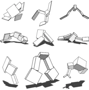
Sims (1994) created a system where 3D creatures can evolve and adapt to its surroundings without the need of user input, or knowledge about the algorithm. Both the morphology and controllers were generated automatically using genetic algorithms. Different fitness functions were then used to evaluate these creatures in different scenarios such as: walking, swimming, jumping and following (see fig. 2.1).
Figure 2.1: From top to bottom: Creatures evolved to swim; Creatures evolved to walk; Creatures evolved to jump(extracted from Sims (1994))
2.1.2
Automatic design and Manufacture
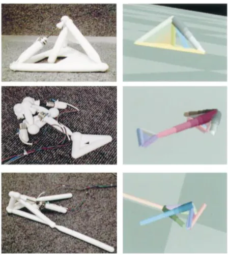
Lipson and Pollack (2000) evolved locomotive systems based on simple blocks. These robots were then automatically fabricated using rapid prototyping tech-niques. Their proposed task was for the robot to walk. The environment used for this task was an infinite horizontal plane. Some of these evolved locomotive sys-tems were symmetric (see fig. 2.2), a possible explanation by the authors is that it is easier for symmetric systems to move in a straight line. Symmetry benefits the system, as it allows the evolved systems to cover a greater area thus gaining more fitness to become the best possible solution. This proposed evolution method is based on the idea that for a system to really adapt and work in the real world, it should be tested in it and not just simulated.
Figure 2.2: The solutions evolved by Lipson and Pollack (right), and their real life prototypes (left).(extracted from (Lipson and Pollack, 2000))
2.2
Genotypes and Phenotypes Generation
Evolutionary algorithms (EA) are algorithms based on biological processes that exist in the real world. These processes include: mutation; selection; reproduction; and recombination.
According to Floreano and Keller (2010), the goal in Evolutionary Robotics is to evolve an artificial body or controller automatically using evolutionary algo-rithms. Genotypes are commonly represented using a string of bits (0s and 1s), where each gene is represented as a single bit. Genotypes just like in nature con-tain the information that influences how the phenotype is formed. Genes in a genotype can represent properties, parts, or states of a robot by encoding these
properties directly or indirectly. Direct encoding is a straight representation of these properties in the simulation, this means that a gene in the genotype directly maps to the same property in the phenotype. While the indirect encoding specifies how the properties should be generated.
Phenotypes are the realization of the generated genotypes. They represent fully grown agents with the attributes of the previously generated genotypes. These attributes can be a direct representation of the genotype attributes, if direct en-coding was used, or they can be the result of the processes applied to the genotype, if indirect encoding was used. These agents as previously mentioned, can be the controller or the morphology of a robot, so a genotype can represent the neural connections of a controller, or the parts that constitute a robot.
To evolve a genotype, the evolutionary algorithm tests it by simulating its behavior to complete the proposed task. How well the genotype performs is determined by the fitness function. The fitness function works by awarding more fitness points the closer the genotype is to completing the task. This genotype is then transformed either directly, or indirectly into a phenotype. To optimize genotypes, there are processes based on Darwins theory of evolution, such as survival of the fittest and blind variations (Gould, 2002), among others. To optimize genotypes we used an approach based on the survival of the fittest.
2.2.1
NeuroEvolution of Augmenting Topologies
Introduced by Stanley and Miikkulainen (2002), NeuroEvolution of Augmenting Topologies (NEAT), is capable of evolving complex solutions and optimizing them. It does so by using the structure as a way to limit the search space of the connection weights. Starting with a minimal structure and then growing it incrementally has been shown to be, not only faster in learning, but also more efficient than minimizing the structure at the end.
NEAT introduces the concept of historical markings. Different genes can be based on the same structure if both derive from the same gene. Knowing their origins,
it is easier to choose two genes to mutate or to crossover that are compatible. The historical marking is a global counter, which the authors called the innovation number. When a new gene appears, the counter is incremented and assigned to the new gene.
NEAT also introduces the concept of protection of innovation through speciation. The idea behind this is to, divide the population so that similar topologies compete against themselves instead of the whole population, thus creating groups where each genome will try to be the best solution of that group. To calculate how close or far from a group the genomes are, the authors used the number of excess and disjoint genes from a given pair of genomes. The more disjointed they are, then the less likely it is that they both derived from the same genome.
Calculating the distance δ as a linear combination of the number of disjointed genes D, and the excess E, with an average weight difference of matching genes (includes disabled ones), see 1 .
δ = C1E N +
C2D
N + C3· W (1)
The coefficients (C1, C2, C3) can be used to adjust the importance of each element
(E, D, W ). While N represents the number of genes in the bigger genome. With all of this, this method is capable of evolving minimal structures into fully complex ones, while keeping them optimized.
2.3
Grippers
A gripper is a type of an end effector that can be attached to the end of a robotic arm. Its main use is to grasp objects. There are different types of grippers, and while they share the same basic function (to grasp), the different types use different techniques to do so. An impactive gripper applies direct force to grasp the object. A common impactive type of gripper is the claw. The ingressive gripper uses needles to penetrate the surface of the object to grasp, while the
astrictive gripper grasps objects by means of suction. The last type of gripper is the contigutive, where the grasping technique is to grasp the object by thermal or chemical methods.
In this study the focus is on the impactive type of gripper. This type of gripper is commonly used with solid objects (mostly dense objects, but also fragile objects).
The first type of grippers was used in an industrial environment, replacing humans in assembly lines to assemble as an example, cars (Devol, 1961). This type of gripper is attached to a robotic arm that is stationary with predefined “states” that make it easier for the gripper to grab the parts to assemble. Nowadays grippers have evolved to be more than just industrialized robots in an assembly line (Tai et al., 2016).
There is a gripper that was created to harvest lettuce (Cho et al., 2002). By using a combination of vision, photoelectric sensors and a controller based on fuzzy logic, it was able to harvest lettuce with a success rate of 94.12% (see fig. 2.3). Grippers capable of performing surgeries have also been created (Bertelsen et al., 2013) (Rateni et al., 2015) . One of the problems associated with grippers that perform surgeries that still remains, is the force feedback (feeling what it is touching and responding accordingly).
While piezoelectric grippers are still difficult to control, they are simple, easy to use and of low power consumption when compared to mechanical grippers, making them a viable alternative to other tools when dealing with micro positioning and handling of small parts (see fig. 2.4).
Figure 2.3: The layout of the harvester gripper mentioned above.(extracted from (Cho et al., 2002))
Figure 2.4: An example of a piezoelectric gripper created by Parker Han-nifin.(extracted from (McDonnell, 2015))
2.3.1
Haptic Identification of Objects
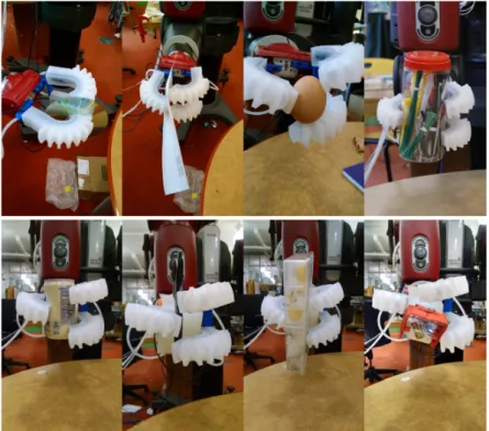
The work of Homberg et al. (2015) was the creation of a gripper capable of grabbing and identifying objects (see fig. 2.5). The novelty of this solution is the use of proprioceptive sensors (can monitor and control its own internal status). With this type of sensors, it is possible to get the readings of what the gripper is currently grabbing, and to change the internal state accordingly.
The fingers were based on soft manipulators, modified with the addition of a bend sensor to measure the curvature around a certain axis.
By building a relation between objects and the configurations necessary for the gripper to grab them, identifying objects by grabbing them becomes a possibility.
The gripper was trained using the k-means algorithm. Each finger’s data was assumed to be independent and was then clustered using k-means to identify objects in a data set.
The authors noted that the only limitation was the resolution of the proprioceptive sensors, so the gripper could distinguish between as many objects as those allowed by the sensors.
Figure 2.5: As we can see, the fingers use a soft material capable of bend-ing to grab objects so the gripper can identify the object it is currently
hold-ing.(extracted from Homberg et al. (2015))
2.3.2
Piezoelectric Grippers
Piezoelectric grippers seem to be the future (Monkman, 2000). Due to their low power consumption and ease of use, this type of actuator seems to be a potential candidate to replace other types of actuators such as pneumatic or electromagnetic.
While pneumatic and electromagnetic actuators need to constantly be fed energy in order to maintain the force they are applying, that isn’t the case with piezoelectric actuators.
Piezoelectric actuators only use current while they are in motion, but, as long as there is some current passing through even when they are turned off, the same force continues to be applied without any extra energy cost.
The piezoelectric actuator recently has been employed as the gripper itself, elimi-nating extra energy costs when compared to more traditional actuators.
Although this is a great way to cut costs, the downside is the force applied by the actuator (it is not as strong as a pneumatic based gripper). Piezoelectric actuators, when compared to the traditional actuators, fall short on the force they can apply in a single stroke. However, this is why the piezoelectric gripper is perfect to grasp small components.
2.3.3
Minimally Invasive Surgery with Grippers
Rateni et al. (2015) proposes a novel gripper that uses soft materials to safely interact with biological tissue. The soft material used by this gripper is elastomeric (silicone-based material). The main advantage of this material is that it can get closer to soft tissue without damaging nearby organs.
The gripper itself is composed by three fingers, disposed in a triangular way so that when they close to grasp something they form a pyramid (see fig. 2.6). This way the stability of the gripper during the grabbing of tissue is assured.
The fingers start in an open position; they close as the cables connected to them are pulled. So, when an object is grabbed, the gripper can adjust to its shape.
While results show that it is safe, the authors also claim that manual calibration of the system at the time, is still necessary. This work shows great promise in the use of grippers in Minimally Invasive Surgery.
Figure 2.6: As we can see, the fingers use a soft material capable of bend-ing to grab objects so the gripper can identify the object it is currently
Evolution, Simulation &
Prototyping
3.1
Evolution
Evolutionary algorithms are a part of artificial intelligence, they are used to gen-erate viable solutions to a given problem. Viable solutions are solutions that can complete the task and fit within the criteria defined by the user. There are many evolutionary algorithms, with the differences among them being how they repre-sent and search for their solutions. For example, genetic algorithm solutions are usually represented by strings of numbers. By representing solutions as sequences of numbers, it is possible to apply operators such as mutation and crossover in directly on the solution. Another evolutionary algorithm technique is genetic pro-gramming. These algorithms’ solutions are computer programs usually represented by trees stored in memory, or as strings.
To find the most viable solutions to solve our task, we decided to use the genetic algorithm. Because this algorithm is inspired by processes found in nature that caused morphologies to evolve to what we currently see in our world, and because this type of evolutionary algorithm is used to find optimal solutions, and has been used to evolve morphologies in experiments such as the ones conducted by Sims
(1994), we believe that it may be capable of evolving a viable solution that can grab and lift an object.
The genetic algorithm is based on biological techniques that exist in nature. Evol-tuions start with a randomly generated population, consisting of a number of solutions, with each solution being evaluated by how well it performs the task. To evaluate the solution a simulation is created that aims to replicate the real life experiment in a simulated environment. A script is executed during the simulation that allows the solution to complete the task. The closer a member of the popula-tion is to completing the task, the better its reward is. This reward is commonly referred to as a fitness value and is calculated during the simulation through a fitness function and is awarded at the end of the simulation.
The fitness function is defined by the user as a means to reward solutions that are closer to completing the task. By rewarding these solutions and by creating the next generations of solutions through mutation or crossing over the different combinations of the highest performing solutions, these new solutions may have a better chance at completing the task.
After all solutions of the population have been evaluated, i.e. a fitness value has been attributed to each solution, the best solutions of that population are chosen to generate a new population. This new population contains the best solutions of the previous generation and new generated solutions based on those with possible mutations. This process is repeated until the last generation is created.
In our experiments, the first generation randomly generates one hundred hands, each starting with three blocks that are positioned randomly in one of five available positions on the palm of the hand (see fig. 3.1). Each block also has its height and length values randomly generated between 2.25cm up to 3.37cm in its height, and from 6.6cm up to 9.9cm. The maximum limit is calculated by multiplying the minimum value (2.25cm and 6.6cm respectively) by 1.5. The width of the block is the only value that remains constant through the evolutionary process, with 1.5cm (see fig. 3.2).
Figure 3.1: The first generation of hands is generated with three blocks ran-domly positioned in the available five positions. R1, R2 and R3 represent the random positions of each block. If a blocks position happens to be shared by
another block, the new block is attached to the already existing one.
Figure 3.2: This figure illustrates the properties of a block. R1 and R2 are
two randomly generated values ranging from zero to one, that when multiplied by the range value gives us the size to add to the default value.
The task in our evolution is to grab an object and lift that object up and hold it, so we simulated this task by writing a script that the hand would follow to grab and lift a given object. The fitness is calculated at each world step after the object is created. Fitness points are awarded or deducted as shown in 2, with I representing the object’s initial position along the Z axis, J representing the object’s current position along the Z axis, and P representing the object’s previous position along the Z axis:
f =
0, if the object’s current position is outside the hands radius
J − I, if the object is moving upwards
J − P, if the object is falling
0.1, if the object is not colliding with the ground
(2)
The first condition prevents solutions that would push the object out of range to be rewarded with fitness points. Without this condition, the best hands were often the ones that would push the object, instead of grabbing and lifting it. The second and third condition check if the object is being lifted or if it is falling. In the first case, the fitness points awarded are equal to how much the object has been lifted off the ground. In the latter, fitness points are deducted from the current fitness value equal to how much the object has fallen since its previous position.
After all solutions have been evaluated, the ten best are chosen to be cloned to form a new population. During the cloning process, each of the ten best hands is cloned ten times, with each clone having a probability of suffering variations that affect the blocks and their values. These variations can include mutations of the length and height of a block, adding or removing blocks and copying a block structure (a set of blocks connected through joints that share the same position in the palm of the hand that form a “finger”) into an available position.
Besides the previously described genetic operators, the evolutionary process has another operator called crossover. A crossover occurs when two members are chosen to reproduce. There are different types of crossover with the simplest being the single point crossover. With single point crossover a point in both parents is chosen at random, the values of both parents are then swapped from that point forward, creating two distinct solutions. The parents’ information is stored in arrays/vectors so that it is possible to generate a random index and perform the crossover operation from that index forward (in single point crossover),
however our solutions are complex data structures represented by objects and not by numbers and as such we didn’t implement this operator.
Each block can suffer mutations or be removed. While for each position available in the palm of the hand a new block can be added or a block structure can be copied (see table. 3.1 for percentages).
This process is repeated until the end of the evolution.
Operations Frequency Probability (%)
Mutation For each block 10 Addition For each position 10 Removal For each block 4 Copy a block structure For each position 4
Table 3.1: Each operation with their frequency and probability.
3.2
Simulator
To run the described experiments, a simulator was built using Java with the sup-port of an open-source library and physics engine called Open Dynamics Engine (ODE) created by Smith (2000). This library was helpful in creating a simulated environment where objects in it are affected by forces in the same way they would be if these experiments were done in the real world.
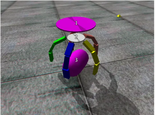
This simulated world consists of the following objects: A support, a hand and its generated blocks, and the object to grab and lift (see fig. 3.3).
The support is a static object created above the hand and can be thought of as the robot “arm” that connects to the hand in the real world. This support is necessary since, ODE is a physics engine and as such, when an object is created inside the simulation, it is immediately affected by the forces acting in the simulation. This means that, as soon as the hand is created in the simulation, it would fall to the
ground due to the effect of gravity, and considering the purpose of this work is to generate a hand capable of functioning in the real world, we could not ignore the effects of gravity in our simulation, so the solution was to create a static object which we called “support”.
The static object is not affected by any of the forces present in the simulation, and its only purpose is to be attached to the hand by means of a slider joint. With this object, we created a mechanism that allows us to control when and how fast the hand should come back up.
The object to grab and lift is a main part of these experiments. This object can take any primitive solid form that exists in ODE, or that can be imported from a 3D object (by loading a custom triangle mesh). The primitive objects already supported by ODE are: rectangles, capsules, cylinders, and spheres.
The primitive objects have parameters such as radius and lengths that can be adapted to better fit our experiments. All the objects have density and mass, and while ODE calculates both of them, taking into account the lengths of the object and its radius (if necessary), we found it necessary to readjust the mass to one similar to the one in aluminum cans as it is a common object found in the real world that can be replicated using primitive objects.
The generated blocks that compose the "fingers" that belong to the hand are generated by the evolutionary process. They can be added, removed, mutated or replicated during evolution. The minimum values for the height and length of a block were defined so that there was enough space to fit a servo for control. Only the width of the blocks was fixed and not subject to mutations by the evolutionary process.
The width is a constant due to initial experiments where we observed that the width of the block was interfering with how the hand could grab the object, being detrimental to solutions as these solutions could not completely close to grasp the object. The length and height can be mutated up to 1.5 times their default size (6.6cm for the length and 2.25cm for the height property).
Block dimensions were calculated to leave enough space for a servo to fit in. The servo we used to replicate these dimensions was the HXT900 Micro Servo. This servo is small but can produce enough force to push objects up to 1.6Kg.
The palm of the hand is a cylinder with 10 centimeters of diameter. In initial experiments, it had twelve positions where blocks could potentially connect, this was later changed to five positions because the blocks were colliding with other blocks in neighboring positions, causing strange behaviors in the simulation, mak-ing it unstable. Table 3.2 presents a summary of the objects used durmak-ing our experiments as well as their properties.
Object Mass (Kg) Height (cm) Width (cm) Length (cm)
Object 0.0152 User Defined User Defined User Defined Block 0.014 2.25 up to 3.37 1.5 6.6 up to 13.2
Hand 0.059 N/A 5 0.5
Table 3.2: Values for each object used in the simulation. The object’s mass is based on the average weight of an aluminum can. The block and hand mass is
Figure 3.3: 1)the support connecting to the palm of the hand; 2)The palm of the hand connecting to multiple blocks; 3)A capsule as the object this solution
is going to try to grab and lift.
ODE does not have a defined unit system. This means that all the values present in the simulation are free for interpretation until we assign them a unit. For example, we can create a cube that is 3x3x3, and ODE won’t assign any units to this cube. It just creates it, so we have to assign some unit of measurement to it.
Depending on the scope of the problem, this unit can be centimeters, meters, or any other unit of measurement that fits the experiments.
This kind of versatility can be good or bad. It’s good because it allows us to simulate big structures without needing to represent them one to one, which means we don’t need a very powerful machine to run experiments.
Other parameters that affect the simulation (see table. 3.3):
World step controls the amount of time, in seconds, passed between each step. How much a step is worth is assigned by the user. ODE recommends to have a small step size so that the simulation runs smoothly. A bigger time step leads to
a bigger jump between steps, which can lead to unstable simulations. In this case we are using steps that move time forward 0.0009 seconds.
Error Reduction Parameter (ERP) is used at each time step to align bodies that are connected by a joint. This is necessary because, as the simulation runs bodies tend to drift away from their positions. If an ERP value is set, a force is applied at the joint to force the bodies back together. This value is user defined, and has a range from zero (no error is corrected) to one (tries to correct all the errors), however the latter is impossible due to internal approximations. And because correcting joint errors is a demanding task, it is not recommended to set the value to one. Correcting all errors can lead to slow simulations, especially if there are a lot of objects connected by joints.
Constant Force Mixing (CFM) combined with ERP allows us to simulate different types of materials by changing their values. CFM, is what determines if a constraint is “soft” or “hard”. In an hard constraint, there are rules that can never be broken, for example, objects can not by default penetrate the ground’s surface, this is called a hard constraint. While a soft constraint allows objects to penetrate, or clip through others. This type of constraint can be useful to simulate various types of soft materials.
Damping is used to reduce instability. It reduces both the angular and linear velocity until both values are below threshold values.
Simulation Parameter Values
World Step 0.0009 sec. Error Reduction Parameter 0.8 (Max Value)
Joint When connected to the palm of the hand: - -45o to 90o of rotation;
When connected to another block: - 30o to 0o of rotation;
Constant Force Mixing 0.00001 (Default Value) Damping Angular Scale: 0.00673
Linear Scale: 0.01832
Table 3.3: Values for each simulation parameter being used during the simu-lation. To prevent blocks from going backwards when opening the hand, joints between blocks can not rotate more than their upper limit value (0o). The
damping scale values were taken from examples provided by ODE.
To prevent clipping between the object and the blocks and the palm of the hand, the simulation starts by first opening the hand. This is done by rotating each blocks’ joint angle close to the joints maximum opening angle (45o degrees for the first blocks and 0o for the rest).
After fully opening the hand, the object appears, thus preventing any possible clipping between the object and the blocks or the palm of the hand.
To check if the blocks are touching or grabbing the object, we had to build a collision detection system based on the one provided by the ODE demo package. For each contact the ODE collide function is called which generates the contact information of two given objects geom (body) that could be intersecting. Then, for each contact it checks if one of the geoms in the contact belongs to the object and if so, it then proceeds to check the other geom to see if it belongs to a block connected to the palm of the hand. If both conditions are met, then that means the object is colliding with a block connected to the palm of the hand, therefore it is being grabbed.
The system starts by creating a buffer of contacts with a limit of contacts, by default it’s 64 contact joints.
Contacts are the objects’ surfaces, and contact joints are created by the collision detection system and are deleted as soon as the current step ends. They serve to prevent objects from clipping into each other by using an “outgoing” velocity. Although there is a default limit of 64 contact joints, we ran experiments with 32 and 128 contact joints. The results showed that the simulation is faster with 32 contact joints while maintaining the same fitness values as a simulation with 64 contact joints when simulating with a primitive object such as a capsule, but returns different values when simulating with complex or imported objects. While simulations with 128 contact joints took longer to finish and had different fitness values even for primitive objects.
Each contact has surface parameters that can be set. These parameters allow us to change how bouncy or soft the surface is, or how slippery, amongst other prop-erties, an object is. See table 3.4 for the values corresponding to those parameters.
Surfaces Values Mode dContactSlip1 dContactSlip2 dContactApprox11 dContactApprox12 dContactSofCFM softcfm 10-5 mu dInfinity slip1 and slip2 150
Table 3.4: Values for each surface parameter of a contact. Some parameters such as softcfm and slip1 and slip2 need to have their corresponding flags set
3.3
Prototyping
Processing is a Java software and library developed by the Processing Foundation (Fry and Reas, 2001) with the purpose of easing the creation of software that can create/generate art. Processing is used all over the world in different ways, from computer courses in art schools to exhibitions in museums such as the Explorato-rium in San Francisco or the Museum of Modern Arts in New York. It also has a very prominent place in research, being used to visualize data in Nokia, Yahoo! and General Motors.
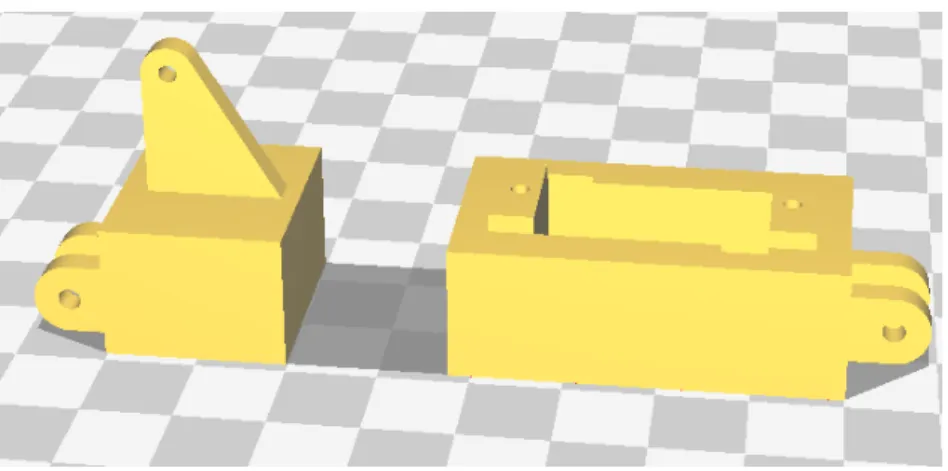
In this work, Processing was used to assemble the generated blocks from the main evaluation process with pre-made parts to create the final piece that could be 3D printed and used in a real world experiments.
In Processing, the block that looks like a fin, and is used to connect the block to another block or to the hand, and the block with the space to insert the servo (fig. 3.4), are combined with the generated block (fig. 3.5). To do this, the block that looks like a fin is inserted at one of the ends of the generated block, and the block with the space for the servo is inserted at the other end.
Because the generated block can have a different width than that of the fin block, a width offset was calculated. With this offset, we can now center the fin block. The same process is repeated with the servo block, but at the other end. The newly assembled piece (fig. 3.6) is then exported into a format that can be read by the 3D printing software. This process is repeated for each generated block in a hand.
Figure 3.4: The fin and servo pieces created outside the simulation.
Figure 3.5: Example of a generated block from the simulation.
Figure 3.6: The final block with both the servo and fin combined with the generated block.
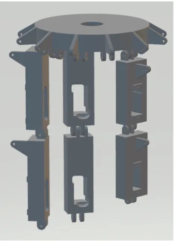
Figure 3.7: The gripper assembled with the modified block pieces. This 3D model represents the gripper shown in 3.7.
Results
The goal of these experiments was to evolve a gripper’s morphology that could grab and lift specific objects through genetic algorithms. A hand that would be capable of grabbing, lifting and holding objects independent of their rotation and size. In our experiments, the initial setup consisted in a hand composed by three randomly generated blocks in three randomly chosen positions of the five available in the palm of the hand, and an object that could be a capsule, a rectangle, a cylinder or a sphere.
In these experiments, the hand followed a script with three steps (see appendix E.1 for an example of a successful hand, and appendix F.1 for an unsuccessful hand):
• Open hand: Each block has a hinge attached to it, and at this step the block rotates over the hinge’s axis towards the outside, therefore “opening” the hand;
• Close hand: After the blocks reach their maximum rotation over the hinge outwards, they start to rotate inwards over the hinge’s axis, as if “closing” the hand;
• Move up: As soon as the blocks collide with the object, the hand starts moving up;
To simulate the opening and closing of the hand, a torque of 0.156 N.m is applied in the joints connecting the blocks to the hand. This torque value is divided by the number of parents a block that is not connected to the hand has.
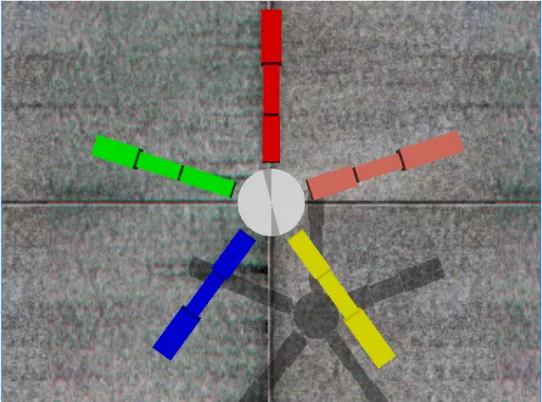
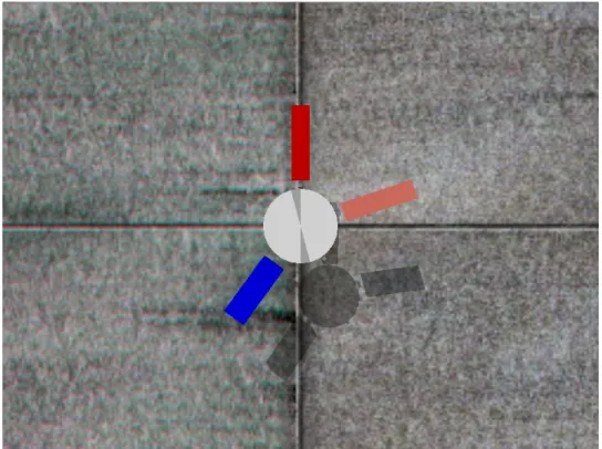
Block morphology was generated with an evolutionary algorithm, more specifically a genetic algorithm. Each generation comprised of 100 genomes, each encoding the morphology of a hand. The hands’ morphology properties values were stored in variables in a Java class. Each hand evaluation consisted in four samples, except for hands evaluated to grab a sphere due to its symmetry. In each sample the initial position of the object has a different angle along the x axis (see fig. 4.1). The first sample had the object at 0oof rotation, and the following samples rotated
the object in increments of 45o. The fitness value attributed to a hand was the average fitness value of the four samples. Each sample had a duration of 4000 steps, with each step moving the simulation forward 0.0009 seconds.
Figure 4.1: For evaluations that used four samples, each sample corresponds to one of these angles demonstrated with a capsule object. Starting with 0o rotation at the top left corner; 45o rotation at the top right; 90o rotation at the
bottom left; 135o rotation at the bottom right;
approach, only the top ten of the evaluated generation are selected with the rest of the hands being discarded.
Each of those top ten hands is cloned ten times, with each clone having a 10% chance of mutating for each block, changing its length or height. For each block there is also a 4% chance of it being removed from the hand. For each position there is a 10% chance of adding a new block and a 4% chance of replicating an already existing block structure, this means that it can copy already existing chains of blocks from one position to other positions.
To evaluate solutions, we created a fitness function that awards fitness points to our solutions. A fitness function, is a type of function that allows us to evaluate how close a solution is to reaching its goal. According to Floreano and Urzelai (2000), a fitness function can be defined in three axes:
• Functional or behavioural: A functional fitness function is based on mea-surements of the components involved in generating a behaviour, such as, the velocity with which the gripper opens or closes. A behavioural fitness function however, is based on the effects of said behaviour, such as, closing the gripper too fast can lead to objects to slip from its grasp;
• External or internal: a fitness function is considered external if its cal-culations are based on variables not readily available to the robot and only available to an external observer. While an internal fitness function is based on the robot having the variables available at the moment through sensors for example;
• Explicit or implicit: An explicit or implicit fitness function depends on the amount and type of constraints explicitly imposed on solutions, such as, specify the size of a blocks length, height or width;
A fitness function works by awarding fitness points to a solution during the sim-ulation. Fitness points are awarded as the solution meets conditions created by
the user. The amount of fitness points is also defined by the user and it varies depending on the task.
Fitness points are rewarded by the height reached by the object, this means that the higher the object is, the higher the fitness points awarded to that hand. Fitness points are deducted in the same way as they are awarded, which means, the bigger the fall, the more points are deducted from the final fitness value. Fitness points are also awarded if the object is not touching the ground. This condition is met if the object’s geom is not colliding with the plane’s (ground) geom.
Fitness points are awarded according to 3 as soon as the “close hand” step of the script starts, and are accumulated during the simulation:
f =
0, if the object’s current position is outside the hands radius
J − I, if the object is moving upwards
J − P, if the object is falling
0.1, if the object is not colliding with the ground
(3)
Where I is the starting position for the object along the Z axis, J is the object’s current position along the Z axis, and P corresponds to the position along the Z axis immediately before the current position.
To reduce the number of false positive results, the fitness function used was ad-justed to benefit solutions where the object being picked up does not cross a threshold, that threshold being the hands radius. With this condition, solutions where the blocks would flick the object far away, therefore being awarded fitness points, are discarded.
Before this condition was added to the fitness function, most solutions would evolve hands that would kick the object across great distances, gaining altitude due to the force applied in the kick, leading to incorrect solutions because the object was never grabbed by the hand.
4.1
General Results
Evaluations were conducted using ten different seed values. An evaluation was created for each size (large, medium, small) of each primitive object in ODE (capsule, cylinder, rectangle and sphere), giving us a total of 120 hands across all evaluations.
Although these 120 solutions are valid, as the hand grabs the object as it should, most of them do not perform as well as they should have to be considered an actual valid solution. To be considered an actual valid solution, a hand should be able to grab, lift and then hold the object until the simulation terminates. As such, we need to filter these solutions that were evaluated and make sure they can actually grab the object without letting it fall. This reduces the number of solutions that can be considered actual valid solutions to 28% of the total number of solutions.
We examined each of the previously evaluated hands in each sample that was used during the evaluation process. If the hand was evaluated with an object that had four samples, each sample contributes a maximum of 25% to the total fitness value. So during this examination if the evaluated hand grabs and lifts the object in a given sample, we award that sample its maximum percentage value. If the hand is able to grab the object but drops the object, we award it with half of the maximum value, which is 12.5%. If the hand is unable to grab and lift the object, we dont award it any fitness.
Hands evaluated to grab and lift sphere objects are evaluated using one sample, so the maximum contribution of that sample to the total fitness value is 100%. In this case, we award a hand that successfully grabs and lifts the object its maximum percentage value, 100%. If the hand grabs the object but the object eventually falls, we award it half of its maximum percentage value, 50%. And 0% if the hand can’t grab the object at all.
After filtering the 120 hands, we can see that 28% of the evaluated hands can in fact grab the object in all samples without dropping it. Hands that could not grab the object and lift it at all make up for 33% of the results, and hands that could
grab and lift the object in at least two of the four samples, correspond to 39% (see fig. 4.2).
Figure 4.2: Evaluations results breakdown.
Of those 28% that can grab and lift the object in all samples, 82% of them were hands evolved to grab the sphere object. Hands evolved to grab capsules represent 15% of these results, with the final 3% corresponding to hands evolved to grab rectangles. None of the hands evolved to grab cylinders were able to grab the object in all samples without dropping it (see fig. 4.3).
Figure 4.3: Breakdown of hands that grabbed the object in all samples.
Hands that failed to grab and lift the object the most, were hands evolved to grab rectangles (45%). This can be explained by the rectangle’s hard edges, unlike those of the capsule, cylinder and sphere, making it harder for the hands to wrap around it.
Close behind as one of the hardest objects to grab and lift, is the cylinder (43%). Although it doesn’t have the same hard edges as the rectangle, the cylinder unlike the capsule and the sphere has flat surfaces, which makes it harder to grab the object in some samples. Hands evolved to grab capsules make the final 12% in this category (see fig. 4.4). Hands evolved to grab spheres never failed to grab the object and lift it of the ground.
Figure 4.4: Breakdown of hands that grabbed the object in half of the samples.
The largest group is the one with hands that grab and lift the object in at least half the samples. Most evolved hands end up in this group because the third sample is in a completely different orientation from the starting angle. If we look at the object from above, we can say that the starting angle with 0o of rotation is the object facing a vertical direction, while the third sample’s angle has the object facing an horizontal direction, this makes it extremely difficult for hands to evolve to grab all four different samples.
And so, many of the hands evaluated with four samples, evolved into successfully grabbing two, sometimes three of the four proposed samples.
A large percentage of hands in this group are those evolved to grab capsules (43%), with hands evolved to grab cylinders and rectangles sharing similar percentages, 28% and 24% respectively. There were two hands that evolved to grab spheres that let the object fall once they reached the limit, this happened because in both solutions one of the hands’ sides was left without any blocks to hold the sphere.
Figure 4.5: Breakdown of hands that grabbed the object less than half of the samples.
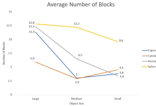
When dealing with bigger objects, the evolutionary process favored hands with more blocks, while hands dealing with medium and smaller objects evolved to use fewer blocks (see fig. 4.6), sometimes even less than the initial number of three blocks. The only exception to this are hands evolved to grab spheres, due to their round configuration, all hands evolved to have no fewer than five blocks across all object sizes.
Medium sized objects seemed to be the hardest to grab and lift, as no hand with the exception of those evolved to grab medium spheres, managed to grab and lift medium objects in all samples.
Medium objects are smaller than large objects, so the torque necessary to grab and lift said objects is also smaller. One way to apply less torque, is to use less blocks, and with less blocks there are fewer chances of a clone to suffer a mutation, however it also means that the mutations that happen will fall on blocks that suffered mutations already.
This also happens to hands evolved to grab smaller objects, but due to their smaller size, these objects are normally grabbed by blocks squeezing the object between them.
The medium object not being as large as the large object, leads to solutions with fewer blocks, combined with not being able to squeeze the object between the blocks like smaller hands, leads to a worse performance by hands trying to grab medium objects.
There is also a tendency across all seeds for the best hands to use the same number of blocks to grab the same object. Hands with more blocks than the average number of blocks for best hands performed worse. What the best hands have in common is that, at least 50% of the positions used are shared across all seeds, this means that at least half of the blocks of the best hands across all seeds for the same object, share the same positions.
Knowing this, the evolutionary process can be sped up, and some previous local maxima can potentially be overcome, as we can now define starting positions and a minimum number of blocks from the for a hand to start with for a given object.
We can also conclude that a completely different orientation is much harder to grab (see the first angle of 0o with the third of 90o), and because the other two
angles are much closer to that first angle, it is understandable why most hands’ evolutions have a worse success rate when it comes to grabbing and lifting the object in its third angle.
4.2
Capsule Results
Hands evolved that could grab and lift large capsules in all four samples always used fifteen blocks (fig. 4.7), while hands evolved to grab medium capsules mostly used just three blocks (fig. 4.8), with varying degrees of success, but none of them could grab and lift the object in all four samples.
Only one hand evolved to grab and lift small capsules managed to do it in all samples (see fig. 4.9).
The fitness graph for the best evolved morphology at each generation and the average values of all 10 seeds that were evolved to grab and lift large, medium and small capsules can be seen in Appendices A.1, A.2 and A.3 respectively.
Figure 4.8: Best hand to grab and lift medium capsules.
4.3
Cylinder Results
To grab large cylinders all hands across the ten seeds evolved to have six blocks split in pairs, with some variation of one pair in a position opposite to the other two pairs (fig. 4.10). Although every hand evolved used just six blocks, all the hands are unable to grab the object, or drops it in at least one of the four samples.
The medium cylinder hands that could grab and lift evolved to have at most three blocks (see fig. 4.11), with all solutions failing to grab and lift the object across all four samples, lifting and grabbing it at most in two of the four samples.
Only one in ten hands was able to grab and lift the small cylinder in one sample (see fig. 4.12), the rest of the solutions failed to even grab the small cylinder.
The fitness graph for the best evolved morphology at each generation and the average values of all 10 seeds that were evolved to grab and lift large, medium and small cylinders can be seen in Appendices B.1, B.2 and B.3 respectively.
Figure 4.11: Best hand to grab and lift medium cylinders.
4.4
Rectangle Results
Most of the evaluated hands evolved to use twelve blocks to grab the large rect-angle, but only one of them could grab and lift the object in all four samples (see fig. 4.13). Solutions with more than twelve blocks had a worse fitness value.
Hands that used ten blocks to grab medium rectangles, could grab it in all four samples, however they could not hold it until the end of the simulation (see fig. 4.14).
Although the best solution to grab small rectangles only uses two blocks, it could still only grab the rectangle in two of the four samples (see fig. 4.15).
The fitness graph for the best evolved morphology at each generation and the average values of all 10 seeds that were evolved to grab and lift large, medium and small capsules can be seen in Appendices C.1, C.2 and C.3 respectively.
Figure 4.14: Best hand to grab and lift medium rectangles.
4.5
Sphere Results
The best hands to grab large spheres are the ones that evolved to have fifteen blocks (fig. 4.16), while twelve blocks seems to be the optimal solution to grab medium spheres (fig. 4.17). Hands with more blocks had a lower fitness value than hands that had fewer blocks, with eight blocks being the best configuration to grab small spheres (see fig. 4.18).
The fitness graph for the best evolved morphology at each generation and the average values of all 10 seeds that were evolved to grab and lift large, medium and small capsules can be seen in Appendices D.1, D.2 and D.3 respectively.
Figure 4.17: Best hand to grab and lift medium spheres.
Robustness Test of Evolved
Morphologies
After the main evaluation experiment, each evolved hand was put through five different scenarios to test their robustness. These scenarios are useful to study how the previously evolved hands behave in different scenarios from the ones they were evaluated in. For that, we devised five different scenarios to test each hands’ overall performance.
Each scenario has random noise applied to the object’s initial position and rotation. This noise consists in small rotations of the object’s x axis (0 to 1 degree) and of the object’s position (0 to 1 mm). These small deviations in rotation and positioning help simulating how an object is placed in the real world.
Scenario 1 - Angles: Each hand was evaluated with four samples, each representing one of the rotation angles along the X axis (0o; 45o; 90o; 135o). In this scenario to each of those angles a small deviation in its rotation is applied (0 to 1 degree) as well as to its position (0 to 1 mm). Each angle is tested one hundred times. Spheres were only subjected to random deviations on their positions.
With noise applied to both the rotation and positioning of the object, we can simulate real life positioning of an object, as such we can prove if the evaluated hands can in fact successfully grab the object they were evaluated to grab and lift during the main evaluation experiments.
During this scenario, all hands that that had the highest fitness when grabing the large capsule object during the main evaluation process, continued to grab and lift the capsule even with the introduced random noise in rotation and positioning, with 100% success rate.
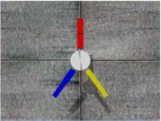
A pattern can be observed with medium evolved cylinder hands through this scenario in that most hands have more success grabbing the first angle, followed by the second angle, and the fourth angle coming in third, with the the third angle coming in fourth with 0% of success across all those hands (see fig. 5.1), which as we concluded during the main evaluation process results, is due to the angles being in different orientations.
The third angle is the most difficult angle to grab and lift the object in, due to its complete opposite orientation when compared to the other angles used. So, the two hands that could grab and lift the cylinder object in this angle, have the worst performance in the other angles (see fig. 5.2).
Figure 5.1: Visualizing the pattern emerging when the object is a medium cylinder.
Figure 5.2: Visualizing the opposite pattern emerging when the object is a medium cylinder.