JOURNAL OF ANALYTICAL ATOMIC SPECTROMETRY, AUGUST 199 1, VOL.
zyxwvutsrqponmlkjihgfedcbaZYXWVUTSRQPONMLKJIHGFEDCBA
6zyxwvutsrqponmlkjihgfedcbaZYXWVUTSRQPONMLKJIHGFEDCBA
353zyxwvutsrqponmlkjihgfedcbaZYXWVUTSRQPONMLKJIHGFEDCBA
Solid Sampling in Electrothermal Atomic Absorption Spectrometry Using
Commercial Atomizers
A
Review
Carlos Bendicho* and Margaretha T. C. de Loos-Vollebregt
zyxwvutsrqponmlkjihgfedcbaZYXWVUTSRQPONMLKJIHGFEDCBA
Laboratory of Analytical Chemistry, Delft University of Technology, De Vries van Heysfplantsoen 2, 2628 RZ Delft, The Netherlands
Summary of Contents 1 introduction
2 Direct Solid Sampling
2.1 Atomization Systems 2.1.1 Graphite tube atomizer 2.1.2 Cup cuvette atomizer 2.1.3 L’vov platform techniques
2.1.3.1 Platform atomization 2.1 -3.2 Boat atomization 2.1.3.3 Microboat atomization 2.1.4 Cup atomizer
2.1.5 Cup-in-tube technique 2.1.6 Carbon rod atomizer 2.1.7 Graphite probe atomizer 2.1.8 Ring chamber atomizer 2.1.9 Second surface atomizer
2.2.1 Influence of particle size
2.2.2 Influence of sample homogeneity 2.2.3 Influence of sample mass
2.2.4 Influence of analyte location in the sample 2.2 Accuracy and Precision
2.3 Chemical Modification 2.4 Sample Introduction Systems
2.5 Sample Preparation 2.6 Calibration
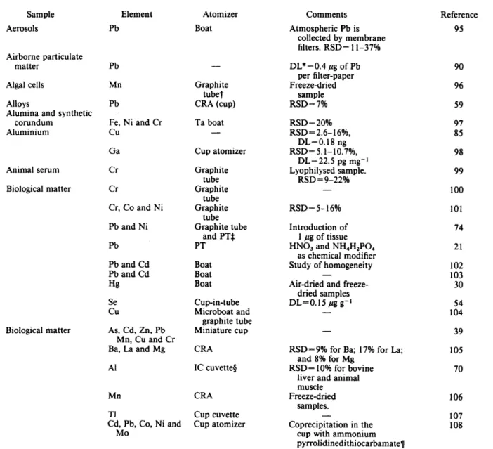
2.7 Applications of Direct Solid Sampling
3 Slurry Sample Introduction
3.1 Preparation and Mixing of Slurries 3.1.1 Use of stabilizing agents
3.1.2 Magnetic stirring and vortex mixing 3.1.3 Ultrasonic agitation
3.1.4 Gas mixing of slurry 3.1.5 Pre-digestion of slurry
3.1.6 Electric dispersion in a condensed medium
3.2 Influence of Particle Size 3.3 Influence of Slurry Concentration 3.4 Chemical Modification
3.5 Calibration
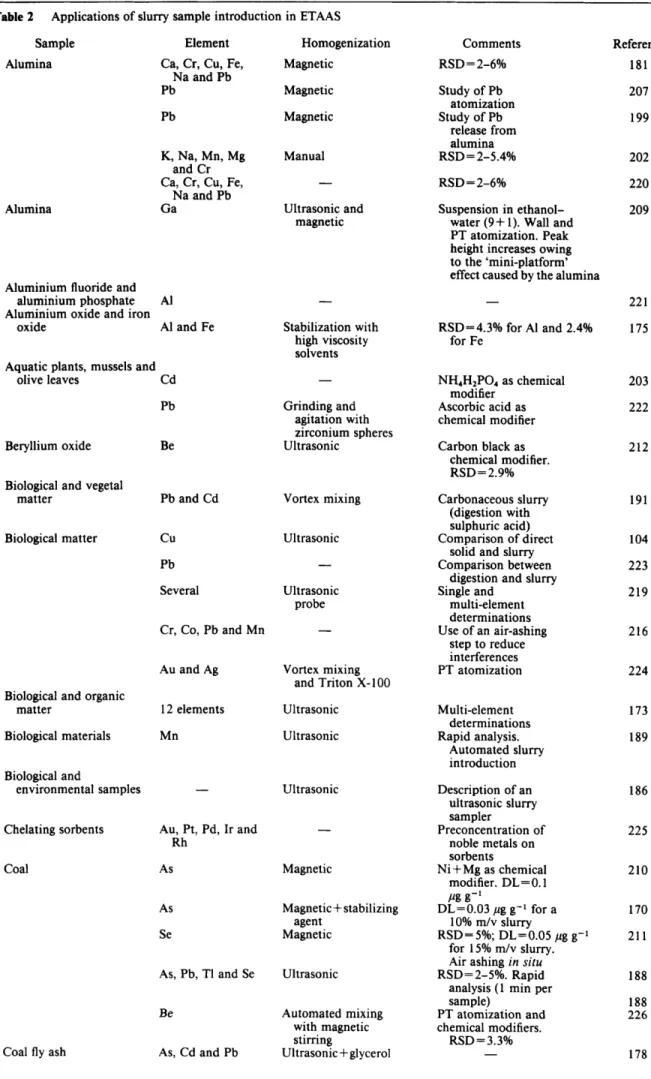
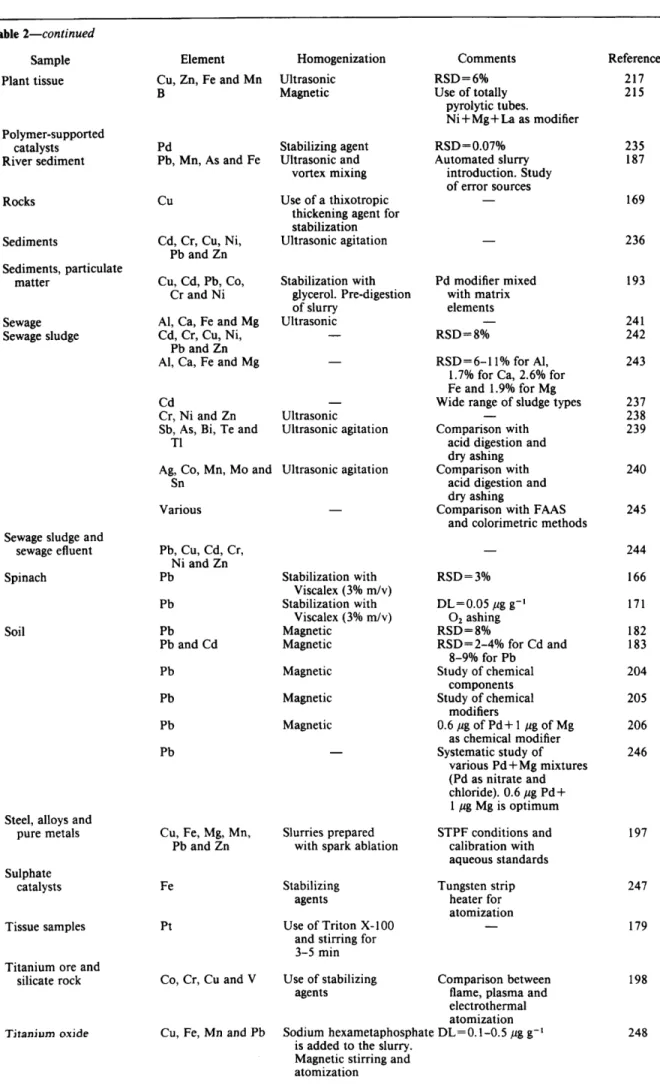
3.6 Applications of Slurry Sample Introduction
4 Direct Solid Sampling Versus Slurry Sample Introduction
4.1 Sample Pre-treatment 4.2 Sample Introduction
4.3 Dilution of the Solid Sample
4.4 Sample Homogeneity 4.5 Peak Shape
4.6 Calibration
5 Conclusions
6 References
Keywords: Direct solid sampling; slurry sample introduction; electrothermal atomic absorption spectrometry;
commercial atomizer; review
* Present address: Perkin-Elmer Hispania,
zyxwvutsrqponmlkjihgfedcbaZYXWVUTSRQPONMLKJIHGFEDCBA
S. .4., Calle La Mas6 2, 28034 Madrid, SpainDownloaded by Universidade Federal de Juiz de Fora on 27 April 2011
Published on 01 January 1991 on http://pubs.rsc.org | doi:10.1039/JA9910600353
354
zyxwvutsrqponmlkjihgfedcbaZYXWVUTSRQPONMLKJIHGFEDCBA
JOURNAL OF ANALYTICAL ATOMIC SPECTROMETRY, AUGUST 1991, VOL. 61
Introduction
zyxwvutsrqponmlkjihgfedcbaZYXWVUTSRQPONMLKJIHGFEDCBA
The success of the technique depends on the skill of the The direct analysis of solid samples, without chemical pre-treatment, is a goal widely pursued in order to simplify the analytical procedure. The application of electrothermal atomic absorption spectrometry (ETAAS) to the direct
analysis of samples is
zyxwvutsrqponmlkjihgfedcbaZYXWVUTSRQPONMLKJIHGFEDCBA
as old as the technique itself.' Electrothermal AAS has received increased attention for thedirect determination of metals at trace levels in a wide variety of samples, owing to its hgh sensitivity, the simplicity of the instrumentation and the relatively low cost.
Several reviews have addressed the solid sampling tech- nique from a general point of vie^,^-^ making reference to either specific ~ a m p l e s ~ - ~ or comparing different atomic spectrometric techniques.' Specific features of solid sampl- ing have been claimed throughout the literature. The advantages of using solid sampling over acid digestion or fusion procedures are obvious, and they can be summarized
as follows:
zyxwvutsrqponmlkjihgfedcbaZYXWVUTSRQPONMLKJIHGFEDCBA
(i) reduced sample pre-treatment and hence, an increase in the speed of the whole analytical procedure; (ii)low contamination risk, an essential requirement when
trace levels of metals are to be determined;
zyxwvutsrqponmlkjihgfedcbaZYXWVUTSRQPONMLKJIHGFEDCBA
(iii) fewer possibilities of analyte losses during the sample pre-treatment or retention by insoluble residues; and (iv) the use of corrosive and hazardous chemicals is avoided.
The number of papers published between 197 1 and 1990 shows the impact of the solid sampling technique (Fig. 1).
In this review, attention is mainly focused on the literature concerning the application of commercially available atom- izers for solid sampling. Among the different procedures for inserting solid samples into the electrothermal atomizer, two approaches are widely used, firstly, direct introduction of the solid sample, and secondly, the introduction of a slurry prepared by suspending the finely divided solid sample in an appropriate liquid diluent.
The period between 1971, the year when the first application of solid sampling with a commercial atomizer was reported,8 and 1980 reflects the early development of the solid sampling technique. The applications reported for solid sampling were characterized by the use of laboratory- built atomizers capable of accepting solid samples, wall atomization, slow heating rates for atomization (ramp times of 1 s and longer), peak absorbance measurements and matrix-matched solid standards for calibration in addition to the use of unreliable and manually-operated sample insertion devices.
analyst in many instances. I t is clear that problems and drawbacks arise when chemical pre-treatment is avoided. These problems are listed below.
(i) Insertion of the solid sample into the atomizer is not as easy as it is for liquid samples. Direct introduction of the sample requires extreme care and training. Loss of sample and contamination can occur during the weighing andor transfer from the balance to the atomizer. This problem is less critical when using slurry introduction.
(ii) A different weighing is required for each replicate in contrast to liquid samples, which use direct insertion. This can make the analytical procedure tedious and clearly unacceptable for routine determinations. With slurry intro- duction several determinations can be performed using only one sample preparation. Some improvement has been achieved by the automation of solid sample introduction for routine determinations (see section 2.1.3).
(iii) Problems arise with standardization that do not occur when working with liquid samples. Matrix depen- dence of the peak shape, and incomplete release of the analyte from the solid sample are commonly found. Calibration with aqueous standards is only successful sometimes and the use of the standard additions method fails when the added analyte is not equally affected by the matrix. Calibration with certified reference materials (CRMs), of very similar matrix to the samples, constitutes the most reliable approach.
(iv) Chemical modifiers are less effective for the direct atomization of solids, as the chemical modifier cannot effectively interact with the analyte which is occluded within the sample particles. Several solid chemical modifi- ers have been tried in order to improve this interaction.
(v) Solid samples offer fewer possibilities for dilution when the concentration of analyte is high, for which, a decrease in the instrumental sensitivity or prior dilution of the solid sample with an appropriate solid buffer are required. The slurry technique allows dilution, but critical
use of dilution is required in order to avoid errors,
zyxwvutsrqponmlkjihgfedcbaZYXWVUTSRQPONMLKJIHGFEDCBA
e.g.,when only a few particles remain in the slurry.
(vi) Precision is worse than for liquid samples. Typically, relative standard deviations (RSDs) are about 10%. Preci- sion can be improved by either decreasing the particle size or increasing the mass used for the determination, when sample inhomogeneity is the main factor affecting preci- sion. For many CRMs, sample inhomogeneity has to be taken into account for sample masses of below 200 mg; this is much higher than the 0.1-10 mg used in solid sampling.
(vii) Parts of the matrix can remain in the furnace after the atomization step, and thereby cause the deterioration of the atomizer. The build-up caused by the matrix can also block the light beam emitted from the radiation source, and hence affect the analytical performance. A cleaning-out step is necessary after a series of measurements in order to avoid this problem.
(viiz9 Spectral interferences are more pronounced when the solid sample is atomized directly. High and structured background signals can cause large errors. The use of a powerful background correction system is required if accurate results are to be obtained. Oxygen ashing can also be helpful to remove non-specific absorbance interferences.
(ix) Specific problems are associated with slurry intro- duction, such as the need to maintain a stable and homogeneous slurry and contamination by the liquid ( x ) Problems arise when determining refractory metals, owing to the incomplete release during atomization and OCClUSiOn in the solid matrix. Higher atomization tempera- tures are required to release the analyte in a reasonable period of time, in comparison with liquid samples.
1970 1975 1980 1985 1990 diluent.
Year
Fig. I
zyxwvutsrqponmlkjihgfedcbaZYXWVUTSRQPONMLKJIHGFEDCBA
N u m b e r of papers published per year in the period between1971 and 1990 in direct solid sampling (solid line) and slurry sample introduction (broken line) based on the 249 references included in the review
Downloaded by Universidade Federal de Juiz de Fora on 27 April 2011
Published on 01 January 1991 on http://pubs.rsc.org | doi:10.1039/JA9910600353
JOURNAL OF ANALYTICAL ATOMIC SPECTROMETRY, AUGUST 199 1, VOL. 6
zyxwvutsrqponmlkjihgfedcbaZYXWVUTSRQPONMLKJIHGFEDCBA
355zyxwvutsrqponmlkjihgfedcbaZYXWVUTSRQPONMLKJIHGFEDCBA
( x i ) Problems can arise in the preparation of blanks, especially when using ground samples.
Many of these problems have been partly solved during the last decade by the implementation of various new instrumental developments and by improving the analytical methodology. Progress in three different lines of develop- ment accounts for the present use of solid sampling as a reliable technique, which is often preferred to the chemical pre-treatment of samples. These include the design of graphite atomizers specifically adapted to handle solid samples; the automation of solid sample introduction; and the use of stabilized temperature platform furnace (STPF) technology.
The introduction in 1981 of improvements in furnace technology by Slavin and c o - w o r k e r ~ ~ ~ ~ ~ under the concept of STPF conditions, can be considered as 'the break- through' allowing the solid sampling technique to become an alternative to the analysis of solutions in routine determinations.
Although direct solid sampling has been widely docu- mented and reviewed, no specific attention has been given to the introduction of slurries. The popularity of this technique as an alternative to direct solid sampling is reflected in the large number of papers published during the last decade (Fig. 1).
In this review, it is mainly commercially available atomizers that are discussed, as laboratory-built atomizers have been extensively treated in previous review^.^-^ Direct solid sampling and slurry sample introduction are both reviewed independently, so that the characteristic features of each approach can be easily overviewed; relevant
applications are included.
zyxwvutsrqponmlkjihgfedcbaZYXWVUTSRQPONMLKJIHGFEDCBA
2 Direct Solid Sampling
Early work reporting direct solid sampling showed that modifications to commercially available atomizers, and the development of laboratory-built atomizers specifically de- signed for solid sampling, were required. The main features
of laboratory-built atomizers for direct solid sampling are:
zyxwvutsrqponmlkjihgfedcbaZYXWVUTSRQPONMLKJIHGFEDCBA
(i) the use of larger dimensions than with the commercially available atomizers in order to facilitate sample introduc- tion, thereby preventing the radiation beam from being blocked and avoiding a high background caused by the solid
matrix;
zyxwvutsrqponmlkjihgfedcbaZYXWVUTSRQPONMLKJIHGFEDCBA
(ii) the separation of the volatilization and atomiza- tion of the analyte; (iii) the use of large sample masses inorder to avoid errors caused by inhomogeneous distribution of the analyte; (iv) the lack of isothermality during atomiza- tion; and ( v ) the use of a low heating rate during atomiza- tion to avoid high background signals.
The atomization of solid samples by using atomizers with larger dimensions than those used for liquid sampling was recommended by L a n g m ~ h r . ~ . ~ Atomizers used for solid sampling can be heated inductively or resistively. Although resistively-heated furnaces are more common, induction furnaces were designed to accommodate solid samples.
Several manufacturers of electrothermal atomizers have implemented specifically designed atomizers for the direct analysis of solid samples. These designs include tube furnaces, platforms, cups and probes. Commercially avail- able atomizers are briefly described below.
2.1 Atomization Systems 2.1.1 Graphite tube atomizer
Graphite tube atomizers are based on the Massmann design" (e.g., Perkin-Elmer and Varian). The solid sample can be introduced into the furnace either through a centrally located hole in the furnace or from the ends of the tube. Tube-type furnaces were widely used during the initial
stage of solid sampling in ETAAS. In 1971, only two years after the introduction of commercial graphite furnace atomizers, Kerbefl determined Au in polyester fibres by direct insertion of the sample. The problems associated with the use of this type of furnace include: troublesome sample introduction; strong spectral interferences; and non- reproducible deposition of the solid sample on the wall. Accurate positioning of the solid sample is important in order to avoid non-reproducible vaporization as a result of the temperature gradient along the tube.
2.1.2 Cup cuvette atomizer
In contrast to the Massman furnace, the cup cuvette atomizer contains the sample in a cup-shaped furnace. This type of furnace is manufactured by Hitachi [Fig. 2(a)]. The main advantage of the cup cuvette atomizer is that the sample vaporization takes place slightly out of the absorp- tion volume so that blocking of the radiation beam, as a result of the sample residue formed after atomization, is avoided. In addition, the cup cuvette atomizer gives reproducible sample deposition. Analytical applications using the cup cuvette atomizer have been reported by Takada and co-workers12-16 for the analysis of metals and alloys. Sensitivity can be improved by covering the cup cuvette with a graphite lid.'' The enhancement is due to an increased residence time of the analyte in the cup. 2.1.3 L'vov platform techniques
L'vov et al.18 proposed the technique in which a platform made of pyrolytic graphite is inserted into the centre of a graphite tube. The sample is deposited on the platform. The platform is mainly heated by radiation from the hot tube wall. As a result, a delay in sample vaporization takes place compared with the vaporization from the tube wall. Consequently, the atomic vapour is formed when the gas temperature in the absorption volume has reached steady- state conditions. Isothermal atomization reduces both spectral and chemical interferences. Several electrothermal atomizers incorporate the platform technique for atomiza- tion. In all of them, a graphite support of varying dimen- sions and relatively low mass is used. The temperature delay depends on the mass of the platform and the contact between the platform and the tube wall. Despite the extensive use of the platform technique for dissolved samples, its application to solid sampling has been more restricted. Chakrabarti et d . 1 9 determined several metals in
oyster tissue using wall and platform atomization and selective volatilization of the matrix. Although similar precision was found by using both techniques, accuracy was better when the sample was atomized from a platform. Likewise, platform atomization offered better sensitivity for volatile metals. Chakrabarti et made a comparison between wall, platform and probe atomization for the direct determination of lead in bovine liver. Accurate results were only found with platform and probe atomization and by measuring the integrated absorbance. A special platform design has been reported by Brown et ~zl.,~' which facilitates the positioning of solid samples on the platform [Fig. 2(b)].
Kufurstz2 compared the different commercial atomiza- tion systems that are available for direct solid sampling. It was concluded that large graphite tubes are required in order to facilitate insertion of the sample and that L'vov platform conditions should be used for atomization.
The manufacturers of graphite furnace atomizers supply a variety of graphite supports such as platforms, boats and microboats which cause some delay in sample vaporization. However, theoretical calculations indicate that the vapour phase temperatures reached with these types of atomizers are lower than for the L'vov platform atomizer, and
Downloaded by Universidade Federal de Juiz de Fora on 27 April 2011
Published on 01 January 1991 on http://pubs.rsc.org | doi:10.1039/JA9910600353
356
zyxwvutsrqponmlkjihgfedcbaZYXWVUTSRQPONMLKJIHGFEDCBA
JOURNAL OF ANALYTICAL ATOMIC SPECTROMETRY, AUGUST 199 1,zyxwvutsrqponmlkjihgfedcbaZYXWVUTSRQPONMLKJIHGFEDCBA
VOL.zyxwvutsrqponmlkjihgfedcbaZYXWVUTSRQPONMLKJIHGFEDCBA
6zyxwvutsrqponmlkjihgfedcbaZYXWVUTSRQPONMLKJIHGFEDCBA
( a )
Tube
zyxwvutsrqponmlkjihgfedcbaZYXWVUTSRQPONMLKJIHGFEDCBA
/
Carbon
Fig. 2 (a) Cup cuvette atomizer; (b) platform-tube atomizer designed by Brown
zyxwvutsrqponmlkjihgfedcbaZYXWVUTSRQPONMLKJIHGFEDCBA
el aZ.;2* (c) L'vov platform atomizer; ( d ) boat atomizer; (e)microboat atomizer; U, miniature cup atomizer; (g) cup-in-tube atomizer; ( h ) carbon rod atomizer; (i)
zyxwvutsrqponmlkjihgfedcbaZYXWVUTSRQPONMLKJIHGFEDCBA
probe atomizer; 0 )zyxwvutsrqponmlkjihgfedcbaZYXWVUTSRQPONMLKJIHGFEDCBA
ring chamber atomizer designed by Schmidt and Falk;64 and (k) second surface atomizer designed by Rettberg and H ~ l c o r n b e ~ ~therefore, increased chemical interferences can be ex- p e ~ t e d . ~ ~ J ~ A brief description of commercially available platform atomizers is presented below.
2. I .3.1 Platform atomization. The L'vov platform sys- tem is supplied with the atomizers commercially available from Perkin-Elmer [Fig. 2(c)]. The mass of the platform is about 75 mg. The insertion of the platform into the tube is axial. Grooved and ungrooved tubes can be used to accommodate the platform. However, this type of support is unsuitable for weighing the solid sample, because part of the sample can be lost during the insertion operation, although this system can be successfully used when the solid sample is introduced through the sampling hole of the tube by means of a solid injector.24
2.1.3.2 Boat atomization. The 'boat technique' is used in the atomizers manufactured by G r i n Analysengerate. The behaviour of this system approaches that of the L'vov platform [Fig. 2(d)]. The deposition area (7 x 4 mm) is open and bordered. The boat has a mass of about 130 mg, and is transferred from the microbalance, used to weigh the solid sample, to the atomizer, by means of a special claw. Insertion is axial and is attained using a jerk-free mechani- cal guide. Sample masses of from 0.2 to 30 mg can be introduced with this system.25 An automated solid sample analysis system based on the boat technique has been developed.26 The AAS instrument includes a powder sampler, an integrated microbalance and a transport and handling system for the sample boat.
The applications reported for this technique include the analysis of metals and alloys,27 fly ash,28 sewage sludge,29 biological matter,3o p~lyethylene,~~ filter matter,32 marine
foodstuff^^^ and salivary calculi.33
2.1.3.3 Microboat atomization. This technique is avail- able in the atomizers manufactured by Thermo Jarrell Ash. The microboat is a 6 x 4 mm and has an approximate mass of 120 mg. The deposition area is open and bordered [Fig. 2(e)]. The microboat containing the solid sample is trans- ferred into the atomizer, in a similar way to the boat
technique, by using a special claw. The microboat is inserted into the graphite tube through a narrow slit. The insertion is radial and there is a low risk of contamination. A disadvantage of the microboat is that the delay in atomization is considerably reduced as the whole microboat surface is in contact with the tube wall.
The microboat technique has been compared with atomi- zation using induction furnaces for the analysis of metallic ~ a m p l e s ~ ~ - ~ ~ and glass materials.37 Induction furnaces can only be operated at a maximum temperature of about 2600 "C, which is 300 "C lower than that with resistively-heated furnaces. Resistively-heated furnaces permit lower charac- teristic masses to be obtained than do induction furnaces. In contrast to resistively-heated furnaces, induction fur- naces allow the use of larger sample masses and hence, lower background absorbances are produced.36
2.1.4 Cup atomizer
The first application of a cup for solid sampling was reported by Price et a1.38 The use of graphite cups inserted into graphite tubes permits not only the safe transfer of sample from the microbalance to the atomizer but also facilitates its weighing. The sample introduction system ensures a reproducible sample-to-sample deposition and, in contrast to the cup-in-tube technique (see section 2.1 S), the deposition can be viewed. The use of a cup for atomization also avoids deterioration of the graphite tube because there is no build-up of deposit on the wall.38 The cost is also significantly lower than that of the graphite tube.
The cup atomizer is used in the electrothermal atomizers manufactured by Hitachi [Fig. 2m]. These atomizers use a miniature cup (2.5 mm diameter; 45 mg mass). The cups are inserted into the graphite tube through an enlarged hole in the middle of the tube; again a special claw is used for insertion. The risk of contamination is low but the area of contact between the cup and the tube wall is large and therefore, the 'L'vov platform effect' is reduced. The
Downloaded by Universidade Federal de Juiz de Fora on 27 April 2011
Published on 01 January 1991 on http://pubs.rsc.org | doi:10.1039/JA9910600353
JOURNAL
zyxwvutsrqponmlkjihgfedcbaZYXWVUTSRQPONMLKJIHGFEDCBA
OF ANALYTICAL ATOMIC SPECTROMETRY, AUGUST 199 1, VOL. 6 357reproducibility from cup-to-cup is sufficient to permit the use of one cup for each determination. The mass of sample that can be introduced ranges from 0.1 to 2 mg.39 Miniature
cups used for solid sampling in the Hitachi atomizers are
zyxwvutsrqponmlkjihgfedcbaZYXWVUTSRQPONMLKJIHGFEDCBA
U-shaped, in contrast to those used for dissolved samples. Atomization with graphite cups has been used for the determination of metals in particulate matter suspended in air,40 steel, Cu and Cu alloys,41 stainless steel, magnesite, Mg-Zn alloys, silica and Si-A1 alloys.38 Several applications for the miniature cup system have been reported such as the analysis of bovine plant matter,44 oyster and biological matter39 and marine organisms.46 The miniature cup has also been used to determine several metals preconcentrated from solution by coprecipitation with S-hydro~yquinoline,~~ dimethylglyoxime (DMG)-Ni- 1 -(2-pyridylazo)-2-naphthol (PAN)48 and magnesium 8-
q ~ i n o l i n a t e . ~ ~ The concentration factors achieved with preconcentration can be as high as 18 O o O - f ~ l d . ~ ~
2.1.5
zyxwvutsrqponmlkjihgfedcbaZYXWVUTSRQPONMLKJIHGFEDCBA
Cup-in-tube techniqueThe cup-in-tube atomizer for solid sampling is manufac- tured by Perkin-Elmer. In consists of a capsule that has an aperture of 3.5 x 4.2 mm and has a mass of approximately 180 mg [Fig. 2(g)]. The capsule is radially inserted through a hole located in the middle of the graphite tube. There is some risk of contamination during the insertion or removal of the capsule from the tube.
The delay produced with this system is significantly larger than that in wall or platform a t o m i z a t i ~ n . ~ ~ The reason for the pronounced delay is the larger mass of the capsule and the protection of the sample from radiational heating. The sample deposition is difficult to observe as the deposition area is closed. The gas above the sample is also shielded from radiational heating by the capsule walls. Gas and sample remain cold until the capsule is heated so that the heating mechanism of the sample is by conduction from the capsule wall. The characteristic masses obtained with the cup-in-tube technique are slightly worse than with the L’vov p l a t f ~ r m . ~ ’ Typically, sample masses of 0.3-1.5 mg are i n t r o d ~ c e d . ~ ~
The applications of the cup-in-tube technique include the analyses of plants and plastic film,53 poly(viny1 chloride) (PVC) and bovine liver,51 coal, coal fly ash and particulate matter,s2 biological matter54 and Ni-based alloys.5s
2.1.6 Carbon rod atomizer
Carbon rod atomizers (CRAs) are open atomizers in which the sample is placed in a cup or tube, which in turn is transversely heated by two graphite electrodes [Fig. 2(h)].
These atomizers, manufactured by Varian, were widely
used for solid sampling,
zyxwvutsrqponmlkjihgfedcbaZYXWVUTSRQPONMLKJIHGFEDCBA
e.g., for the determination of metals in particulate matter suspended in air. The airsamples were filtered through cups or tubes made of porous graphite, which subsequently were fitted in the atom- izer.56-58 A CRA can be operated under isothermal or non- isothermal atomization. Lundberg and F r e ~ h ~ ~ reported that isothermal atomization using a CRA with a cup offered better precision and accuracy for the determination of lead in steel and Ni-based . alloys. Lundberg60 indicated that
integrated absorbance is preferable for measuring the atomic absorption signal even when the temperature of the carbon cup rises continuously during the atomization step and when using non-isothermal atomization. Precision was reported to be better when using integrated absorbance in comparison with peak height.
2.1.7 Graphite probe atomizer
Probe techniques proved to be useful for isothermal atomization. A probe of graphite is inserted into a graphite tube that is pre-heated to atomization temperature [Fig.
2(i)]. This atomizer is commercially available from Philips. As the probe is primarily heated by radiation transfer from the hot tube, atomization of the analyte takes place at a constant temperature of the gas phase. The probe technique has some advantages over the platform technique.20 In solid sampling, the high matrix concentration can promote the removal of the atomic vapour from the atomizer as a result of the rapid increase in temperature. This can change the residence time of the analyte in the absorption volume. In probe techniques, the temperature of the tube is constant when the sample is inserted, so that this effect is minimized. More importantly, probe atomization facilitates the dissoci- ation of molecular species. Probe atomization was used by
Chakrabarti et
zyxwvutsrqponmlkjihgfedcbaZYXWVUTSRQPONMLKJIHGFEDCBA
aL61 for the determination of Pb, Cd, Ni, Cu and Mn in airborne particulate matter, by prior collectionof the solid particles on the probe. Chakrabarti et uI.~O made a comparison between wall, platform and probe atomiza- tion for the determination of lead in bovine liver. Reliable results were obtained with both probe and platform atomization. Probe atomization offers the advantage that drying and pyrolysis of the sample can be achieved outside the tube, thereby eliminating some of the interferences caused by the matrix. Background signals caused by smoke condensation on cooler parts of the tube is also avoided. Schron et a1.62 used a graphite rod to insert solid geological samples into a graphite tube atomizer. Khammas et aI.(j3
reported the use of wall and probe atomization to deter- mine copper in milk powder. Wall atomization required the use of the standard additions method in order to obtain accurate results. In contrast, however, calibration using aqueous standards was feasible when probe atomization was used.
2.1.8 Ring chamber atomizer
Schmidt and Falk64 designed a special graphite tube for direct solid sampling. The tube has rotational symmetry, and a sample chamber that is isolated from the absorption volume [Fig. 20)]. The sample is accurately positioned owing to the tube configuration. Relatively large amounts of the solid sample (up to 10 mg) can be introduced. The ‘ring chamber tube’ does not have temperature gradients along the area where the sample is contained and it avoids blocking of the radiation beam. The metal vapour enters the absorption volume when the gas phase temperature is stabilized, because of the small temperature gradient that occurs along the sample area and the short ramp time. This design was used to determine Au in gold wire for microelec- tronics, and Cu and Ni in plant matter.64
2.1.9 Second surface atomizer
Rettberg and H o l ~ o m b e ~ ~ achieved an effective separation between vaporization and excitation processes by condens- ing the atomic vapour on a cooled Ta surface (second surface atomizer). The system combines the use of a Ta plug onto which the analyte species condense and a tube-type furnace [Fig. 2(k)]. Although the atomizer was originally used for liquid sampling,66 it is particularly useful for solid sampling, because of the separation of the vaporization and excitation processes. The solid sample (0.7-4 mg) is weighed into a graphite cup using a microspatula and then the cup is placed in the tube and the Ta plug inserted. The tube is heated so that analyte vaporization and deposition on the Ta plug take place (transfer step). In contrast to the
cup atomizer (section 2.1.4), the contact between the
Downloaded by Universidade Federal de Juiz de Fora on 27 April 2011
Published on 01 January 1991 on http://pubs.rsc.org | doi:10.1039/JA9910600353
358
zyxwvutsrqponmlkjihgfedcbaZYXWVUTSRQPONMLKJIHGFEDCBA
JOURNAL OF ANALYTICAL ATOMIC SPECTROMETRY, AUGUST 1991, VOL. 6zyxwvutsrqponmlkjihgfedcbaZYXWVUTSRQPONMLKJIHGFEDCBA
sample cup and the tube is good, and consequently, thetemperature delay between cup and wall is small. During the transfer step, the Ta plug is cooled by a gas stream in order to promote analyte condensation. Once the atomic vapour is deposited on the Ta plug, the cup containing the sample matrix is removed from the tube (cool-down step). The Ta plug is inserted, the cooling gas stopped and the tube heated to a high temperature so that the analyte is re- vaporized from the Ta surface. The atomic absorption signal is independent of the matrix and the background signal is low as a result of the separation of the analyte and the matrix during the transfer step. Recoveries are in the
range 8 1
-
zyxwvutsrqponmlkjihgfedcbaZYXWVUTSRQPONMLKJIHGFEDCBA
127% for citrus leaves, fly ash, river sediment and filter paper.65 A second surface atomizer was used byRettberg and H ~ l c o m b e ~ ~ to measure the time-dependent vaporization rate of an analyte from an individual sample over several heating cycles. The data were related to the total amout of analyte in the sample using aqueous standards. The method was used to determine Pb in tin, copper and steel?’
2.2 Accuracy and Precision
Apart from the errors that can arise during the weighing of the solid sample, the transfer operation and the sample introduction, there are also errors associated with direct solid sampling, which depend on particle size, homogeneity of the sample, sample mass and analyte concentration.
2.2.1
zyxwvutsrqponmlkjihgfedcbaZYXWVUTSRQPONMLKJIHGFEDCBA
Influence of particle sizeMost of the materials require grinding in order to reduce the particle size of the sample to an appropriate size (e.g., 5
pm). Grinding of the material is also recommended for solid samples that are originally in powder form, when the analyte is non-homogeneously distributed. Grinding im- proves the contact between the surface of the atomizer and the solid sample. The grinding operation is not always easy to perform (e.g., for metallic samples) and requires great care in order to avoid contamination.
For refractory materials, such as rocks and minerals, vaporization of the analyte is often influenced by particle size. Improved accuracy and precision have been reported when the particle size is reduced. Eames and Matousek68 observed a decrease of the sampling error in the determina- tion of silver in quartzite rocks when the particle size was decreased by grinding to less than 10 pm. In addition, accuracy can be improved by grinding, as the analyte is more readily released.
Stoeppler et al.69 concluded that small sample masses yield low concentration values when the sample is insuffici- ently ground. There is some controversy in the literature about the influence of grinding of the solid sample. In several types of samples (e.g., biological matter) particle size has no influence on accuracy but only on precision, whereas for refractory materials (rocks, minerals, etc.),
vaporization of the analyte is often influenced by particle size. Takada and HirokawaI2 concluded that the surface area of the sample particles influenced the vaporization of the analyte. Integrated absorbance was measured for re- peated atomizations of the same sample, until complete vaporization of the analyte was achieved. Frech and Baxter70 found that increasing the mass of the sample did not always cause a proportional increase of the atomic absorption signal. Calibration with aqueous standards for the determination of A1 in biological material was feasible, provided that the mass of the sample was lower than 2 mg.
Precision is poor when the sample is introduced into the atomizer as a single particle. Takada and Koide” indicated this problem in the determination of Cu, preconcentrated using an ion-exchange resin and using wall atomization.
2.2.2 Influence of sample homogeneity
The influence of inhomogeneity is more critical when the sample mass decreases (typically, sample masses of 0.1
-
10 mg are used). The lowest sample mass that can be handled reflects the difficulty of weighing and introducing the sample into the atomizer. Lundberg and F r e ~ h ~ ~ studied the trace element distributions for metallic samples and con- cluded that the influence of inhomogeneity on precision was negligible, even working with sample masses as low as 2 mg. Siemer and Wei73 also found that the homogeneity did not affect the precision for sample masses of about 1 mg when determining Pb in rocks and glasses. On the other hand, the relative homogeneity of solid samples can be estimated from precision measurements and sample mass.69v70For materials that display non-homogeneous distribution of the analyte, precision can be improved by grinding. For a large number of solid materials, the influence of homogene- ity is not critical for sample masses of less than 200 mg.
2.2.3 Influence of sample
zyxwvutsrqponmlkjihgfedcbaZYXWVUTSRQPONMLKJIHGFEDCBA
massThe sample mass introduced into the atomizer is related to the analyte concentration in the original solid sample. The range of sample that is suitable is determined, firstly, by the availability of a microbalance to handle small sample masses and, secondly, from the capability of the atomizer to accept larger sample masses. Several workers suggested using larger graphite tubes than those commercially avail- able, in order to introduce sample masses of up to 200 mg. The use of larger sample masses mainly improves the precision, especially for non-homogeneous samples.
The range of the sample mass that can be introduced is limited. Although sample masses of approximately 1 pg have been sample masses of lower than 0.1 mg are difficult to handle, i.e., to weigh and transfer. When the concentration of the analyte of interest is too high for the analytically useful working range of the calibration graph, either less sensitive l i n e ~ , ~ ~ J ~ dilution of the sample with graphite4ss68*7s-78 or increase of the internal flow of ArS3 can be used. However, these procedures can be a source of error. Vapour phase temperatures are lower when an internal gas flow is used and therefore, matrix interferences are enhanced.
2.2.4 Influence of analyte location in the sample
Different types of bonding between the analyte and the solid matrix, in addition to different locations of the analyte in the solid particles (i.e., on the surface or occluded within the solid particles), can influence the absorbance measure- ment, because of different vaporization kinetics. One example was the determination of several metals in steel. Signals with double peaks were observed as a consequence of the occurrence of the two locations of the analyte in the steel grain.13 The formation of several peaks in the atomic absorption signals was also observed for the determination of Pb in plasticss1 using the cup-in-tube technique, and was attributed to the way the plastic decomposed when the temperature was increased. Several peaks were observed when lead was atomized at low pressure from copper alloys, which were ascribed to different chemical forms of Pb, or changes in its location.79
2.3 Chemical Modification
Chemical modifiers are used in ETAAS for several pur- poses.*O The addition of a suitable reagent to the sample can change the relative volatility of the matrix or analyte, so that no interference due to the matrix occurs during the atomization step. Stabilization of the analyte by a chemical
Downloaded by Universidade Federal de Juiz de Fora on 27 April 2011
Published on 01 January 1991 on http://pubs.rsc.org | doi:10.1039/JA9910600353
JOURNAL OF ANALYTICAL ATOMIC SPECTROMETRY, AUGUST
zyxwvutsrqponmlkjihgfedcbaZYXWVUTSRQPONMLKJIHGFEDCBA
199 1, VOL. 6zyxwvutsrqponmlkjihgfedcbaZYXWVUTSRQPONMLKJIHGFEDCBA
359modifier avoids early losses that can occur during the pyrolysis and ramping steps of the atomization. Chemical modification for direct solid sampling is more complicated than for dissolved samples, as the contact between the solid particles and the modifier is less effective. The addition of chemical modifiers has been used to diminish the volatility of the analyte, to improve its release from the solid particles, or to avoid the formation of double peaks. Chemical modifiers for direct solid sampling have been used in liquid and solid form.
Chemical modifiers in liquid form are mostly used for the determination of highly volatile elements such as Pb, Cd, Se
and
zyxwvutsrqponmlkjihgfedcbaZYXWVUTSRQPONMLKJIHGFEDCBA
As. The chemical modifiers most widely used are: H3P0481 or H3P04+
(NH4)2HP0482 and HNO, orHN03
+
NH4H2P0421 for Pb; H3P0483 or NH4H2P04+HN0321~52 and H3P04 or Mg(N03)284 for Cd; HN03+Ni or HN03+Pd54 for Se; and H2S04+ HN03+Ni46 for As. Baxter and F r e ~ h ~ ~ reported that the use of Pd(NO& +Mg(N0,)2 rather than NH4H2P04+
Mg(N03)2 as a modifier for Pb and Cd determinations in solid samples gives superior results.In many instances, a chemical modifier added in liquid form is ineffective for stabilization. de Kersabiec and BenedettiE4 carried out a study on the effect of chemical modifiers in liquid form, including H3P04, Mg(NO& and Ni(N03)2, on the atomization of geological samples using the miniature cup and cup cuvette atomizers. Different samples were also atomized with the addition of chemical modifiers in the solid form. Double peaks were still obtained when liquid or solid modifiers were used.
Graphite powder, added to the solid sample, is used to dilute the sample, so that the mass of analyte atomized falls within the linear range of the calibration graph. In addition, the graphite powder when mixed with the sample prevents the residue, formed after atomization, from fusing or sintering, decreases chemical interferences and promotes the release of the analyte as the atomization occurs in a
reducing
zyxwvutsrqponmlkjihgfedcbaZYXWVUTSRQPONMLKJIHGFEDCBA
environment.45~68.75-78,85,86 Moreover, the lifetime of the atomizer is increased. Rapid deterioration of thesurface of the atomizer was observed upon atomization of
samples that contained large amounts of silicon. The silicon forms globules at high temperature, which attack the pyrolytic graphite surface.68
The use of chemical modifiers in a solid form requires the modifier and sample to be ground and mixed so that the contact between them is good. Durnberger and co-work- e rfound that Ni, used as a finely divided powder, was ~ ~ ~ ~ ~ ~ effective in stabilizing Se. It was essential that Ni was added in elemental form and in a 15-fold higher concentration compared with the amount used for liquid samples.
2.4 Sample Introduction Systems
Four basic procedures have been used for sample introduc- tion in direct solid sampling. Firstly, the introduction of a support on which the sample is weighed; once the sample is introduced into the atomizer the support is re-weighed. This procedure is used in most tube-type atomizers. The weighing and transfer operation requires care in order to minimize any contamination and possible sample losses. The Ta solid spoon commercially available from Perkin- Elmer belongs to this group of devices. The sample can be introduced through the dosing hole of the graphite tube, provided the hole is enlarged.20 For solid samples consisting of ion-exchange resins used for preconcentration of metals from a solution, a set of plastic tweezers and a small funnel can be used to introduce the resin particles into the tube.71
The second procedure, a more advantageous approach, is to use a graphite support for both weighing and atomiza- tion. Such systems are based on platforms, boats, micro- boats, cups and probes, as mentioned before. The use of
inert supports made of ashless paper and cellulose acetate has also been attern~ted.,~ Inert supports tend to cause high blank values and moreover the residue formed after atomization can degrade the accuracy and reduce the lifetime of the atomizer.
The third procedure involves the introduction of the sample by the use of special injectors. In order to facilitate the sample introduction through the sampling hole of the graphite tube, solid sample injectors, operated in a similar way to conventional autosamplers, have been described.
Grobenski
zyxwvutsrqponmlkjihgfedcbaZYXWVUTSRQPONMLKJIHGFEDCBA
etzyxwvutsrqponmlkjihgfedcbaZYXWVUTSRQPONMLKJIHGFEDCBA
al.24 developed an injector to introduce fiiiely powdered samples into a tube-type atomizer. The injectorworks like a microsyringe and sample masses ranging from
0.5 to
zyxwvutsrqponmlkjihgfedcbaZYXWVUTSRQPONMLKJIHGFEDCBA
5 mg were introduced. A different injector used for direct solid sampling was described by Kurfiurst et Thereproducibility of the results is comparable to those obtained for manual solid sample introduction.
The final procedure is the use of special sampling devices to collect the solid sample, by filtration through porous graphite or electrostatic accumulation. These special sampl- ing devices are useful for solid materials suspended in gases.56-58,81-83 Collection on filters made of different ma-
terials
zyxwvutsrqponmlkjihgfedcbaZYXWVUTSRQPONMLKJIHGFEDCBA
(ie., cellulose acetate or nitrate, and PVC) has also been2.5 Sample Preparation
Sample treatment for solid sampling should be kept to a minimum in order to avoid possible contamination or loss of sample; although grinding, sieving, homogenization,
drying
zyxwvutsrqponmlkjihgfedcbaZYXWVUTSRQPONMLKJIHGFEDCBA
etc., are often required. Because of the influence of particle size on accuracy and precision, grinding of thesample is carried out in order to convert the sample into powder form or to reduce the particle size. The grinding can be performed using agate mortars or vibrational pulveriz- ers. Grinding is suitable for brittle materials such as rocks, minerals, glass, soils etc. Biological and vegetal materials can be converted into a solid that can be ground, i.e., by drying, dry ashing, plasma ashing or Iyophilization. Grind- ing metallic samples is more troublesome and can cause contamination of the sample.
2.6 Calibration
The solid matrix can strongly influence the shape of the signal obtained during atomization. This influence makes it troublesome to use peak height to quantify the atomic absorption signal. The fast transient signals require fast instrumental response and preferably integrated absor- bance m e a s ~ r e m e n t s . ~ ~
Calibration can be performed using several approaches:
(i) with CRMs; (ii) with synthetic solid standards; (iii) using the standard additions method; or ( i v ) with aqueous standards.
The first approach requires appropriate CRMs to be available at the concentration level of the analyte of interest. This is not a general calibration method, owing to the lack of reference materials with certified analyte concentrations covering the range of interest (e.g., for environmental samples). However, calibration with CRMs has been used for solid sampling of metallic samples,92 sewage sludge,26 biological samples93 and plant
It should be noted that a significant disadvantage of reference materials is that the certified concentration generally has an uncertainty, which is large when compared with the measurement uncertainty of the method. Conse- quently, the use of CRMs as calibrants will introduce a large and often ignored uncertainty in the final value. In some instances, when CRMs are not available, a synthetic solid sample, that matches the composition of the original sample, can be used.
Downloaded by Universidade Federal de Juiz de Fora on 27 April 2011
Published on 01 January 1991 on http://pubs.rsc.org | doi:10.1039/JA9910600353
360
zyxwvutsrqponmlkjihgfedcbaZYXWVUTSRQPONMLKJIHGFEDCBA
JOURNAL OF ANALYTICAL ATOMIC SPECTROMETRY, AUGUST 199 1, VOL. 6The standard additions method has been used to suppress the influence produced by the bulk composition of the solid sample. This method requires that the analyte contained in the solid sample and the added analyte are equally affected by the matrix. Three different approaches are possible for the standard additions method in combination with solid ~ a m p l i n g . * ~ * ~ ~ In the first approach increasing amounts of analyte are added to constant masses of solid sample. This is difficult to achieve, as it requires weighing identical amounts of solid sample for each individual addition. The second approach involves the use of increasing masses of solid sample with the addition of constant amounts of analyte from a standard solution. In this approach only one standard solution is used and one addition is made and therefore, the final result can be inaccurate. The third approach means varying both the solid sample mass and the standard additions amount. The absorbance signal is a function of two independent variables and can be extracted by multiple linear regression.
The use of aqueous ~ t a n d a r d s ~ ~ - ~ ~ ~ ~ ~ requires that the absorption signal is independent of the bulk matrix, and only dependent on the concentration of analyte. This requirement is usually not fulfilled because of both the spectral and chemical interferences caused by the matrix.
For calibration with aqueous standards to be successful a set of instrumental requirements has to be met, i.e., rapid signal processing, integrated absorbance measurements, Zeeman background correction and atomization under isothermal conditions. For solid samples, the absolute calibration of the autosampler or pipette used to dispense the standard solutions is also important because the accuracy of the determinations is directly dependent on the
accuracy of the pipette.
zyxwvutsrqponmlkjihgfedcbaZYXWVUTSRQPONMLKJIHGFEDCBA
2.7 Applications of
zyxwvutsrqponmlkjihgfedcbaZYXWVUTSRQPONMLKJIHGFEDCBA
Direct
Solid SamplingThe applications of direct solid sampling in
ETAAS
are shown in Table 1. Applications are classified alphabetically, with respect to the matrix. Information on the elements that are determined, the type of atomizer used and the analytical performance are also given. Attention has been mainly focused on commercially available atomizers.3 Slurry Sample Introduction
The introduction of a suspension of the finely powdered sample (slurry) combines both the advantages of liquid and solid sampling.166 This technique was first used by Brady
Table
zyxwvutsrqponmlkjihgfedcbaZYXWVUTSRQPONMLKJIHGFEDCBA
1 Applications of direct solid sampling in ETAAS SampleAerosols
Airborne particulate matter
Algal cells Alloys
Alumina and synthetic Aluminium
corundum Animal serum Biological matter
Biological matter
Element Pb Pb Mn Pb
Fe, Ni and Cr c u
Ga Cr Cr
Cr, Co and Ni Pb and Ni Pb Pb and Cd Pb and Cd Hg Se c u
As, Cd, Zn, Pb Ba, Mn, Cu and Cr La and Mg A1
Mn
TI
Cd, Pb, Co, Ni and Mo
Atomizer
Boat
zyxwvutsrqponmlkjihgfedcbaZYXWVUTSRQPONMLKJIHGFEDCBA
-
Graphite tubet CRA (cup) Ta boat
- Cup atomizer Graphite
tube Graphite
tube Graphite
tube Graphite tube
and PTS PT Boat Boat Boat Cup-in-tube Microboat and
graphite tube Miniature cup CRA
IC cuvetteg CRA Cup cuvette Cup atomizer
Comments Atmospheric Pb is
collected by membrane filters. RSD= 11-37% DL*=0.4 pg of Pb
per filter-paper Freeze-dried
sample RSD= 7% RSD = 20%
RSD=2.6-16'41, RSD= 5.1-10.7%, DL=0.18 ng
DL=22.5 pg mg-l Lyophilysed sample.
RSD=9-22Oh
RSD= 5-
zyxwvutsrqponmlkjihgfedcbaZYXWVUTSRQPONMLKJIHGFEDCBA
16% Introduction of1 pg of tissue
zyxwvutsrqponmlkjihgfedcbaZYXWVUTSRQPONMLKJIHGFEDCBA
HN03 and NH4H2P04as chemical modifier Study of homogeneity Air-dried and freeze-
dried samples DL=O. 15 pg g-l
RSD= 9% for Ba; 1 7% for La; and 8% for Mg
RSD= 10% for bovine liver and animal muscle
Freeze-dried samples.
- Coprecipitation in the
cup with ammonium pyrrolidinedi thiocarbamatef
Reference 95 90 96 59 97 85 98 99 100 101 74 21 102 103 30 54 104 39 105 70 106
107
108
Downloaded by Universidade Federal de Juiz de Fora on 27 April 2011
Published on 01 January 1991 on http://pubs.rsc.org | doi:10.1039/JA9910600353
JOURNAL OF ANALYTICAL ATOMIC SPECTROMETRY, AUGUST 199 1, VOL. 6
zyxwvutsrqponmlkjihgfedcbaZYXWVUTSRQPONMLKJIHGFEDCBA
36 1zyxwvutsrqponmlkjihgfedcbaZYXWVUTSRQPONMLKJIHGFEDCBA
TablezyxwvutsrqponmlkjihgfedcbaZYXWVUTSRQPONMLKJIHGFEDCBA
1-continuedSample Element Atomizer
c u Miniature cup
Comments
Three solid standards ( N E T ( / ) are used for Calibration: coprecipitates with magnesium oxinate, and DMG-Ni-PAN Pb and Cd profiles are
determined in birds'
feathers
zyxwvutsrqponmlkjihgfedcbaZYXWVUTSRQPONMLKJIHGFEDCBA
-
Solid sampling and wet digestion are compared Deuterium and Smith-
Hieftje background correction are compared
Reference 93
109 110 1 1 1 112
113 24 114 44 49
115 94
116 117
Pb and Cd Boat
A1 Cup-in-tube
Cr, Pb, Cd, Boat
Cd Boat
Ni and Hg
Biological and
vegetal matter P Graphite
tube Pb, Rb, Cd, Cu PT
Ni and Mn
Nine elements Boat Pb, Cd, Mn, Cu,
Zn and Cr Al, Cd, Co, Cu,
Mn, Ni, Pb and Zn
Miniature cup Miniature cup
Peak area. Special injector is described
Coprecipitation with magnesium 8-quinolinate. Multi-element analysis
- Generalized standard
additions method for calibration
Automated introduction
- CRA
Al, Ag, Ni and Se - Pb, Cd, Zn, Mn and
Se Cup atomizer
Probe technique c u
Ni and Ag chemical modifiers are attempted. For Se, calibration with solid standards is required
also freeze-dried samples
Direct introduction and 118
Pb and Sb -
Biological matter from a river
ecosystem Cu, Pb, Cd and Zn Boat Biological matter
and marine organisms As Miniature C U D
119
RSD= 3- 10%
Standard additions method
RSD for calibration = 5.5-
zyxwvutsrqponmlkjihgfedcbaZYXWVUTSRQPONMLKJIHGFEDCBA
13%. Aqueousstandards for calibration RSD = 9.6%
RSD = 6.3-7.3%,
DL=5.1 pg
graphite. RSD = 4.9%
additions method for calibration
Ni
Calibration with aqueous standards is well suited for Pb and Zn, but not for Mn. RSD= 5 1 4 % . Pipette method for sampling
Sample mixed with RSD = 10%. Standard
RSD = 10% for Cd; 10-20% for
Dilution with graphite.
46 120 Bovine liver Cu, Zn, Pb, Co,
Fe and Cd Pb
Graphite tube Graphite tube. and PT
PT and probe 20
Cd Pb
Miniature cup
Miniature cup 42 43
Calcium carbonate Coal
cu
Miniature cup 121Be Graphite tube 122
Cd and Ni Pb, Zn and Mn
Cup-in-tube 52
123 Cup cuvette
Coal and particulate matter
Coal and petroleum coke
Copper
Se Boat DL=O.l pg g-I
RSD = 7-2 1 '/o
Standards are prepared by quantitative doping of high-purity Cu
77
Cu, Ni and V
Ag Graphite tube Boat 124 92
Fibre and plastic paper Filter material Fly ash
Freshwater mussels
Cu, Fe, Mn and Si
Cd Boat
TI Boat
A], Cr, Cu, Pb and
Graphite tube Graphite tube Zn
125 126 28
I 2 7
- - - Freeze-dried
samples
Downloaded by Universidade Federal de Juiz de Fora on 27 April 2011
Published on 01 January 1991 on http://pubs.rsc.org | doi:10.1039/JA9910600353
362
zyxwvutsrqponmlkjihgfedcbaZYXWVUTSRQPONMLKJIHGFEDCBA
JOURNAL OF ANALYTICAL ATOMIC SPECTROMETRY, AUGUST 1991, VOL. 6 Table 1-continued Sample Gallium arsenide Geological samples Glass Graphite Hair Hair Inorganic samples Ion-exchange beads Malt and yeastMargarine Marine foodstuffs Metal and alloys Metals (Ta, Fe and Metals and oxides Nickel-based alloys Fe-W) Oyster tissue Paper Particulate matter Pancreatic tissue Pancreatic tissue Pancreatic tissue Petroleum
Phosphorized Cu alloy Pig liver
Plankton Plant and
biological matter Plant matter and
oyster mussels
Element Cr Cr
As, Cd, Pb, Hg, Sb and Se Ag, Pb and Bi Pb
Pb 13 elements Cu, Ag, Coy Ni and
Pb
As, Cd, Cr, Hg and Pb
Pb and Cd T1
Ni
Cd, Pb and Hg Bi, Pb, Ag and Te Ca
Several
Pb, Bi, Se and Te As, Sb, Se and Te Cd, In and Zn
Pb
T1, Bi, Te, Se and Pb
Cd, Pb, Zn, Cu, Co and Fe Cd, Hg, Cu and Cr 10 elements Pb Be Cd
Se, Ag, Hg, Pb, Hg
Pb
Be and Cd
Cd, Hg and Cu Ca
Cd Cd Be Pb
Pb, Cd and Zn Cu and Cr Pb and Cd
Cr
Atomizer Comments
Graphite tube
zyxwvutsrqponmlkjihgfedcbaZYXWVUTSRQPONMLKJIHGFEDCBA
-miniature cup and PT study
- -
Cup cuvette, Chemical modifier Microboat and
Cup cuvette induction furnace Graphite, tube Graphite tube Boat - Cup-in-tube Boat Boat Microboat and induction furnace - Boat
Graphite tube and Microboat and CRA
induction furnace Microboat and induction furnace Cup-in-tube Graphite tube Boat CRA CRA (cup) CRA (CUP) CRA (CUP) CRA (tube) CRA (tube) Cup atomizer Boat Graphite tube CRA Graphite tube and CRA Graphite tube Boat Graphite tube Cup-in-tube - Miniature cup
Dilution with graphite. DL=0.03 ng of Pb DL=O.Ol pg g-' Dry ashing followed
by atomization Silk and animal hair
are used as solid standards
-
Signal summation method is used to improve the signal-to-noise ratio. Calibration with aqueous standards is feasible
- Sample is a chip of
the metal DL= 50 pg of Ca
- RSD=7-25'h DL=O.l, 0.1, 0.06
and 0.003 pg g-' for
As, Sb, Se and Te, respectively RSD= 12% for Zn, 8% for Cd and
7Oh for In. DL=10, 2 and 10 ng g-l for Zn, Cd and In, respectively
Calibration with
standard additions method.
DL=0.5 pg
zyxwvutsrqponmlkjihgfedcbaZYXWVUTSRQPONMLKJIHGFEDCBA
g-' of Pb,RSD = 4.9Oh
Calibration with aqueous standards and use of chemical modifiers. RSD=6-14%
Peak height. Standard additions method for calibration
- - RSD=4.2Oh
RSD = 1 5%
zyxwvutsrqponmlkjihgfedcbaZYXWVUTSRQPONMLKJIHGFEDCBA
- RSD = 7- 1 4Oh
RSD = 6Oh
Collection on filter Collection on
filter. RSD = 1 Ooh
RSD = 14.8Oh
- -
DL= 1 ng g-I of Be (HGA) and Atomizer is modified 10 ng g-I of Be (CRA)
for vacuum atomization -
Pd +magnesium nitrate is more suitable than NH4H2P04+ magnesium nitrate DL=7 pg RSD=6-9%, Reference 128 129 84 37 130 131 132 133 76 134 135 136 25 34 137 27 138 35 36 139 5 5 19 140 141 81 56 83 57 58 40 32 142 143 144 145 79 146 147 23 45
Downloaded by Universidade Federal de Juiz de Fora on 27 April 2011
Published on 01 January 1991 on http://pubs.rsc.org | doi:10.1039/JA9910600353
JOURNAL OF ANALYTICAL ATOMIC SPECTROMETRY, AUGUST 199 1, VOL. 6
zyxwvutsrqponmlkjihgfedcbaZYXWVUTSRQPONMLKJIHGFEDCBA
363 TablezyxwvutsrqponmlkjihgfedcbaZYXWVUTSRQPONMLKJIHGFEDCBA
1 -continuedzyxwvutsrqponmlkjihgfedcbaZYXWVUTSRQPONMLKJIHGFEDCBA
Sample Element Atomizer Comments Reference 50 148 53 51 8 31 149 150 151 152 71 153 154 82 73 38 155 33 47 86 28 26 68 75 156 157 13 12 60 158 159 160 72 41 15 16 17 14 161 77 162 163 Plant, soil As, Cd, Cr, Cu,
Pb and Mn Pb
Cu, Cd, Mn and Rb
Cup-in-tube CRA Cup-in-tube Cup-in-tube Graphite tube Boat
Graphite tube CRA Boat
RSD =
zyxwvutsrqponmlkjihgfedcbaZYXWVUTSRQPONMLKJIHGFEDCBA
1 0%Plastic RSD= 15% RSD = 3.1 - 1 2% Plastic film, PVC
Polyester fibre Polyethylene Polymers PVC air filter Rat placenta
and bovine liver Cr, Pb and Cu Au
Pb, Cu, Cr and Ni Fe, Cu and Cr Be
Cd
RSD = 4-6%
DL=0.02 pg g-'
- Freeze-dried sample.
DL=0.005 ng
Comparison of microwave digestion and direct solid sampling. Samples were diluted with urea RSD=4.1%
RSD= 10-20% RSD= 10-20%
O2 ashing Red mud Cd, Cr, Pb, Ag and PT
Au
Resin (cation-exchange) Cu Graphite tube Rocks and sediments
Rock samples
Cd Graphite tube Au and Ag CRA Pb PT Rocks, glasses and
Rocks and alloys Sediment, soil,
fly ash
leaves and water
Pb CRA (cup) Pb, Na, Fe and Ti Cup atomizer
RSD = 8%
Pb, Cd and Cu Boat Digestion is recommended for soil and solid sampling sediments and leaves Salivary calculi
Sea-water Cd, Pb and Zn As, Cd, Zn, Pb and Boat Miniature cup Zn
I
Preconcentration with 8-hydroxyquinoline.
RSD=6-14%
Several NIST
and BCR standards Pb and Cd Cup-in-tube Pb, Cd and Hg Boat Cd Boat Ag CRA (cup)
and boat
Study of homogeneity Sewage sludge -
Automated system Dilution of sample
with graphite.
RSD=8.l%
Dilution with graphite Aqueous standards
for calibration
O2 ashing
Study on double peaks DL=0.1, 0.04 and 0.008
ng of Cu, Mn and Ag, respectively
-
RSD = 3.840%
Silicate rocks
Siliceous materials Ca, Mg and Fe Ta boat Silicon Pb, Sb and Mn Microboat Spinach
Steel
Rb Graphite tube Pb, Bi, Ag and Zn
Cu, Mn, Ag and Pb Cup cuvette Cup cuvette Pb CRA Ag, Bi, Cd and Zn
Pb and Bi CRA CRA (cup) Steel and Ni-based
alloy
Steel, Fe-Mo and Ni-based alloy Steel, Cu, and
Cu alloy Tin
Pb, Bi, Zn and Ag Microboat RSD = 6%
Pb and Sb Graphite tube Pb Cup atomizer Zn and Bi Cup cuvette Pb and Cd Cup cuvette
DL=34 ppb
RSD = 3.6-9% for Pb and
Sensitivity is RSD = 9-43%
5- 12% for Cd enhanced by covering the cup with a lid RSD= 6-28Oh RSD = 7-9%
RSD= 7- 12Oh Pb Cup cuvette
Tin ingot
Uranium oxide (U,O,) Cu and Ag Cd and Li Cup cuvette CRA Co, Cr, Cu, Mn and CRA Ag, Ca, K, Li, Mg, CRA c o Miniature cup
Ni
Na, Pb, Sn, and Zn
Vitamin B12 Calibration with a synthetic reference
material. DL= 0.15 ng ml-1 of Co or 4 ng mg-I of vitamin B12
Downloaded by Universidade Federal de Juiz de Fora on 27 April 2011
Published on 01 January 1991 on http://pubs.rsc.org | doi:10.1039/JA9910600353
364 JOURNAL OF ANALYTICAL ATOMIC SPECTROMETRY, AUGUST 1 99 1 ,
zyxwvutsrqponmlkjihgfedcbaZYXWVUTSRQPONMLKJIHGFEDCBA
VOL.zyxwvutsrqponmlkjihgfedcbaZYXWVUTSRQPONMLKJIHGFEDCBA
6 TablezyxwvutsrqponmlkjihgfedcbaZYXWVUTSRQPONMLKJIHGFEDCBA
1-continuedSample Element 'Atomizer Comments Reference
Water
zyxwvutsrqponmlkjihgfedcbaZYXWVUTSRQPONMLKJIHGFEDCBA
co
Miniature cup Sample was mixed with 164 20 mg of Mg and 2%8-hydroxyquinoline (2-5 ml) for preconcentration Water borne
Water samples Cd, Cu, Mn, Pb and Miniature cup Coprecipitation Wheat
particulate matter Cd, Pb and Cu Boat -
Zn with DMG-Ni-PAN Cd Boat -
*
DL, detection limit.f Graphite tube, heated graphite atomizer (HGA) and graphite tube atomizer (GTA).
$ PT, atomization with L'vov platform.
9
IC cuvette, integrated contact cuvette.fi IUPAC name, ammonium pyrrolidin- 1 -yldithioformate.
)I
NIST, National Institute of Standards and Technology [formerly known as NBS (National Bureau of Standards)]. 89 48165
zyxwvutsrqponmlkjihgfedcbaZYXWVUTSRQPONMLKJIHGFEDCBA
and c o - ~ o r k e r s ~ ~ ~ J ~ * to determine Zn and Pb in leaves and marine sediments. The slurry technique overcomes some of the problems associated with direct solid sampling as it permits sample introduction using micropipettes and auto- samplers, which are routinely used in liquid sampling. Another remarkable feature of slurry introduction is that the same atomizers that are used for liquid sampling can be successfully used for the atomization of slurries. Most of the work done in slurry sampling has been carried out using wall atomization and platform atomization with tube-type atomizers. The most critical factor in the slurry technique is probably the need for maintaining a stable slurry during the time required for sample introduction. So far, homogeniza- tion procedures include the use of stabilizing agents, magnetic and ultrasonic agitation, vortex mixing, gas mixing and pre-digestion of the slurry. The particle size of the solid sample can have a strong influence on accuracy and precision. Successful slurry analysis requires the char-
acterization of:
zyxwvutsrqponmlkjihgfedcbaZYXWVUTSRQPONMLKJIHGFEDCBA
(z] the sample homogeneity; ( i i ) the grinding and sieving; (iiz] the preparation of the slurry (i.e., the liquidmedium by the addition of chemical modifiers and wetting agents, and antifoam agents); (iv) the mixing and homogeni- zation of the slurry (i.e., the use of stabilizing agents or agitation systems); (v) the extraction of analyte into the slurry medium (i.e., influence of the acidic diluent and efficiency of the agitation system in achieving extraction of the analyte); (vi) the influence of particle size on deposition of the slurry sub-sample, (i.e., the concentration range of the slurry required to obtain reproducible and representative sampling; and (vii) the influence of particle size on atomization efficiency (i.e., the determination of the rela- tive atomization efficiency for the slurry sample and the possibility of using aqueous standards for calibration).
3.1 Preparation and Mixing of Slurries
Preparation of the slurry consists of adding a liquid diluent to the solid material that has been previously ground and sieved (when necessary), weighed and placed into a con- tainer, in which the slurry is stable during the time required for sampling. The amount of solid material that is weighed depends on the concentration of the analyte and the dilution in the final volume of the slurry. For samples of low homogeneity, the precision is improved when larger
amounts of sample are used to make the slurry. The
zyxwvutsrqponmlkjihgfedcbaZYXWVUTSRQPONMLKJIHGFEDCBA
introduction of the slurry sub-sample into the atomizer can be carried out manually or by using an autosampler. When autosampler cups are used in the weighing of the solid material, the maximum volume of slurry is limited to the
cup volume (about 2 ml), which, in turn, limits the maximum amount of material that can be suspended.
Once the slurry is prepared, the solid sample must be equally distributed in the volume of the liquid. The different approaches available to maintain a stable and homogeneous slurry are discussed.
3.1.1 Use of stabilizing agents
Slurry preparation in aqueous solution is rarely suitable because most powdered materials undergo rapid sedimen- tation. Sedimentation of the suspended material usually occurs after mixing the slurry and can be quantified by using Stoke's law. The sedimentation rate depends on the densities of the diluent and solid material, the viscosity of the diluent medium and the radius of the sample particles. The slurry can be stabilized using a highly viscous liquid medium. So far, g l y ~ e r o l , l ~ * J ~ ~ non-ionic surfactants' 74 and organic solvents of high have
been used as slurry stabilizing agents. The stabilization capability of these reagents largely depends on sample characteristics and particle size. As pointed out by Majidi and H o l ~ o m b e , ~ ~ ~ the time interval between complete mixing of the slurry and the removal of an aliquot for analysis can be increased in a highly viscous medium, with
a density similar to that of the particles.
Fuller and Thompson169 used a thixotropic thickening agent to stabilize slurries prepared from rock samples. The procedure consisted of the addition of sodium hexameta- phosphate as wetting agent and ammonia to neutralize the medium. The slurry was stable for several days.
Stabilizing agents are useful when an autosampler is used to introduce the sample, as the slurry can be left in the sampling cups without further homogenization. 17* Little-
john et all7' observed that the stabilization of the slurry was dependent on both the particle size and the concentra- tion of the stabilizing agent. Sample deposition was difficult owing to the high viscosity of the medium, when the Viscalex concentration was greater than 2-3Oh.
On the other hand, the maximum slurry concentration to be used depends on the concentration of the stabilizing agent. Stephen et ~ ~ 1found that the maximum slurry . l ~ ~
concentration was 10% when a stabilizing agent concentra-
tion of the order of
zyxwvutsrqponmlkjihgfedcbaZYXWVUTSRQPONMLKJIHGFEDCBA
3Oh was used for slurries prepared from a spinach sample (50 pm particle size). Similar behaviour wasobserved when glycerol was used as the stabilizing agent.
Problems are reported with respect to the use of viscous media in slurry preparation. The sample aliquot is ineffici- ently pipetted into the atomizer when the concentration of
Downloaded by Universidade Federal de Juiz de Fora on 27 April 2011
Published on 01 January 1991 on http://pubs.rsc.org | doi:10.1039/JA9910600353