Abstract—In this paper, a new multiobjective genetic
algorithm (MOGA)-based approach is proposed to optimize the metal grid design in order improve the electrical performance and the conversion efficiency behavior of the solar cells under high intensities of illumination. The proposed approach is applied to investigate the effect of the metal grid patterns, with a circular busbar surrounding the active area (circular grid), on the electrical performance of high efficiency c-Si solar cells under concentrated light (up to 200 suns). The dimensional and electrical parameters of the solar cell have been ascertained, and analytical expressions of the power losses and conversion efficiency, including high illumination effects, have been presented. The presented analytical models are used to formulate different objective functions, which are the prerequisite of the multiobjective optimization. The optimized design can also be incorporated into photovoltaic circuit simulator to study and show the impact of our approach on the photovoltaic circuit design.
Index Terms—cell, multiobjective, optimization, metal grid,
efficiency, power losses.
I. INTRODUCTION
HE strong demand for alternatives to fossil fuel based energy sources and growing environmental concerns have increased interest in solar cells as a long-term, exhaustless, environmentally friendly and reliable energy technology [1-4]. Continuous efforts to develop new materials and modeling techniques for solar cells are being made in order to produce new photovoltaic devices with improved electrical performances. In addition to the new semi conducting materials, solar cells consist of a top metallic grid or other electrical contact to collect electrons from the semiconductor and transfer them to the external load. In a solar cell operating under the normal conditions, even a small deviation from the optimum power condition can cause a loss of conversion efficiency [1].
T. Bendibis with the Laboratory of Advanced Electronic, Department of Electronics, University of Batna, 05000, Algeria (e-mail: bendib05.t@ gmail.com).
F. Djeffalis with the Laboratory of Advanced Electronic, Department of Electronics, LEPCM, University of Batna, 05000, Algeria (e-mail: faycaldzdz@ hotmail.com).
A. Maouchais with the Laboratory of Advanced Electronic, Department of Electronics, University of Batna, 05000, Algeria (e-mail: [email protected]).
In addition, the enhancement of a solar cell’s conversion efficiency not only depends on materials and device structure; it is also very important to optimize the front metal grid design. The losses associated with the grid directly influence the conversion efficiency of solar cells. This effect is even more pronounced at high intensities of illumination. Maximum power can be extracted from a solar cell only when it is operating with optimum design parameters. In order to minimize the solar cell power losses and maximize the conversion efficiency, new design approaches are required to enhance the reliability and electrical performance of the devices for photovoltaic applications. Numerous authors have modeled and studied the impact of power losses effect on the solar cell electrical behavior [1], [5-8]. In addition, until now, there are no studies to investigate the global electrical performance optimization of the metal grid design by using a global evolutionary-based optimization technique. One preferable approach is the multiobjective-based optimization, which could provide practical solutions for the photovoltaic circuit design. The first step of our approach consists of an accurate analytical presentation of different loss mechanisms including solar illumination. The different analytical models can be used in our study as objective functions.
In this paper, we present the applicability of the multiobjective genetic algorithm optimization (MOGA) approach to optimize the front metal grid design for photovoltaic applications. The key idea of this approach is to find out the best dimensions and electrical parameters of the metal grid to facilitate and improve the device design strategy. Design optimization, which is adopted in this work, is the process of finding the maximum/minimum of the power losses and conversion efficiency called the objective functions and must also satisfy a certain set of specified requirements within constraints [9], [10]. In this paper, we present an alternative approach based on MOGAs, where the designer can specify several objective functions simultaneously. The main advantages of this approach are its simplicity of implementation and provision of several possible solutions to the designer to choose the best device front metal grid design.
II. MOGAS-BASED COMPUTATION
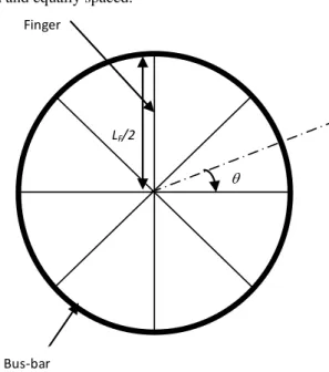
We have investigated a top contact grid structures with a circular busbars surrounding the active area (circular grid pattern, Fig. 1). For this geometry, the fingers are considered
A New Front Metal Grid Design Approach to
Improve the Circular Solar Cell Efficiency
Using Multiobjective Computation
T. Bendib, F. Djeffal, A. Maoucha, D. Arar and N. Lakhdar
T
Proceedings of the World Congress on Engineering 2012 Vol II WCE 2012, July 4 - 6, 2012, London, U.K.
ISBN: 978-988-19252-1-3
ISSN: 2078-0958 (Print); ISSN: 2078-0966 (Online)
uniform and equally spaced.
An evolutionary-based optimization technique has been defined as finding a vector of decision variables satisfying constraints to give acceptable values to all objective functions, [9],[10]. The MOGAs differ from most of all optimization techniques because of their global searching carried out by one population of solutions rather than from one single solution. Due to the simple mechanism and high performance provided by MOGAs for multiobjective global optimization, MOGAs can be applied to study and improve the solar cell design strategy.
An optimum grid metal design minimizes the combined effect of the four loss mechanisms directly associated with the front metal grid design: (1) shadowing loss due to grid reflection; (2) grid-metal resistance; (3) contact resistance between the metal and the semiconductor; (4) emitting layer resistance. Other loss mechanisms in the solar cell typically have little or no dependence on the pattern selected for the metal grid, and therefore, are not included into the analysis [6,7].
In the front metal grid, the power losses caused by each mechanism for the investigated structure, including the illumination levels, of the series resistance (Eqs.1), contact resistance (Eqs.2)), metal resistance (Eqs.3) and by the shadowing (Eqs.4) can be calculated using the fowling analytical expressions [1,6,7,11] for both designs as
) ( 6
) ( 2 2 1
C V
L C J P
mp F mp
s
(1)
t W C V
C J L P
F mp
mp F m
) ( 5
) (
3
2
(2)
F mp
F mp c
W C V
L C J P
) (
) (
3
(3)
2 4
2 2
F F F
F F F F
L L W
L W L W P
(4)
The global loss for the design is given by:
4
1 i
P
GL (5)
where P1 represents the loss due to the lateral current flow in the top diffused layer, P2is the loss due to the series
resistance of the metal lines, P3 is the loss due to the contact resistance between these lines and the semiconductor, P4 is the loss due to the grid shadowing. GL represents the global loss caused by four mechanisms simultaneously, WFis the finger width, t represents the finger thickness,mrepresents
the metal resistivity, sis the sheet resistance of emitter layer,
c
is the contact resistance; LFrepresents the finger length, is half-angle formed between two consecutive fingers.
) (C
Jmp and Vmp(C) represent the optimum current density and voltage under solar illumination, respectively, given by:
) 1 ( )
( mp
mp C CJ
J and Vmp(C)Vmp(1)Vtln(C), with )
1 (
mp
J and Vmp(1) are the optimum current density and voltage at 1 Sun, respectively, C is the concentrator factor,
t
V represents the thermal voltage.
The variables which play a role in determining the loss componentsinclude cell parameters which are established by the fabrication process, parameters which describe the grid design and values which depend on the illumination profile. The grid pattern is described by: WF, t, , m, s,c and
F
L . The values which depend on the illumination profile are: )
(C
Jmp and Vmp(C). Our study is focused to optimize the
metal grid design for the circular grid pattern.
For the purpose of MOGA-based optimization of the electrical performance of the solar cells, routines and programs for MOGAs computation were developed using MATLAB 7.2, and all simulations are carried out on a Pentium IV 3-GHz 1-GB-RAM computer. For the implementation of the MOGAs, tournament selection, which selects each parent by choosing individuals at random, is employed and then choosing the best individual out of that set to be a parent. Scattered crossover creates a random binary vector. An optimization process was performed for a population size of 100 and a maximum number of generations equal to 500, for which the stabilization of the fitness function was obtained for the circular structure. Four objective functions are considered in this study (power losses). Thus, the obtained design can provide the best electrical performance by satisfying the following objective functions:
Bus‐bar Finger
LF/2
Fig. 1. The investigated front metal grid designs: circular grid pattern.
Proceedings of the World Congress on Engineering 2012 Vol II WCE 2012, July 4 - 6, 2012, London, U.K.
ISBN: 978-988-19252-1-3
ISSN: 2078-0958 (Print); ISSN: 2078-0966 (Online)
Minimization of global loss function GL as,
4
1 i
i
iP
w Min
MinGL (6)
where wiand Pi represent the weight function and the power
loss associated with each mechanism, respectively.
The input normalized electrical and dimensional variables vector, which will be optimized using our approach, is given asX (WF,t,LF,m,s,,c), where n represents the number of fingers.
The constraints to be satisfied are:
- ]g1(x):x[ximin,ximax , xiX (each design variable is
confined within a given range). It is to note that the design variables are selected by satisfying the experimental results provided by the literature [5-7].
- g2(x):WF t. - g4(x):LF t.
If low power loss due to grid reflection, grid-metal resistance, contact resistance between the metal and the semiconductor and emitting layer resistance is the required parameter by the device designer, the four loss mechanisms are equally important. Hence, w (i = 1i −4) can be assigned
equal values as 0.25. Given the clearly defined problem to be solved and a bit string and the candidate solutions, the adopted MOGA works as follows [9], [10]:
- Calculate the overall objective function of each of the chromosomes “X” in the population.
- Create “N” offsprings from the current population using the three MOGA operators, i.e., selection, crossover, and mutation.
- Replace the current population with the updated population.
- Repeat the preceding steps until the termination criteria are reached.
III. RESULTS AND DISCUSSIONS
The MOGA parameters were varied, and the associated optimization error was recorded. For the optimized configuration, the overall objective function was 5.65×10⁻³, and almost 100% of the submitted cases were learned correctly.
Fig. 2 shows the variation of overall objective function as a function of the generation number, where the minimum objective functions can be reached for 5000 iterations for the circular grid pattern.
The steady decrease in the global losses function of the best solution in each generation (until it reaches a best possible value) can be attributed to the selection procedure used, i.e., a tournament wheel selection. The final optimized metal grid design parameters are summarized in Table I. The developed MOGA-based approach can be used as the interface between device modeling and photovoltaic circuit simulator such as PC1D in order to optimize the electrical photovoltaic circuit performance under illumination conditions.
Fig. 3 shows the variation of the power losses as function of
illumination levels; it is clearly shown that under concentrating light, the circular grid pattern with optimization has less power losses compared to the another design without optimization. For low illumination levels the difference is important but it decreases with the illumination level. Although the power losses of a grid pattern increase with metal finger resistivity, as expected, the circular grid pattern is less sensitive to this variation. This means that the circular
0 100 200 300 400 500 0,0056
0,0058 0,0060 0,0062 0,0064 0,0066 0,0068 0,0070 0,0072 0,0074 0,0076
O
v
e
ral
l obj
e
ct
ive f
u
n
ct
ion
Generations
Best Fitness=5.69E-3
Fig. 2. Variations of normalized overall objective function with generations.
TABLE I
OPTIMIZED METAL GRID DESIGN PARAMETERS OF CIRCULAR PATTERN
Symbol Quantity Optimized design
Design without optimization
F
W Finger width Gate 10µm 100µm
t Finger thickness 2.5 µm 20 µm
Half-angle 0.1 rad 0.1 rad
m
Metal resistivity 1×10⁻⁶/ 3×10⁻⁶/ s
Sheet resistance 10/ 50/
c
Contact resistance 5×10⁻⁵ .cm 1×10⁻⁵ cm.
F
L Finger length 1cm 1cm
GL (1sun)
(1sun)
Global Loss Efficiency
2. 67 % 27.14 %
22. 09% 21.73%
0 50 100 150 200
0 10 20 30 40 50 60 70
80 Circular grid without optimization Circular grid with optimization
Insolation level [No. of suns]
Po
wer
l
o
ss
es [
%
]
Fig. 3. The calculated power losses at different illumination levels the circular grid pattern.
Proceedings of the World Congress on Engineering 2012 Vol II WCE 2012, July 4 - 6, 2012, London, U.K.
ISBN: 978-988-19252-1-3
ISSN: 2078-0958 (Print); ISSN: 2078-0966 (Online)
grid design is preferable with the increment of the illumination level. In addition, it is observed that a reduction in the power losses can be obtained by introducing our MOGAs-based approach to design of the front metal grid.
The conversion efficiency for illuminated solar cell is given [6, 12] by:
)) ( 1 ( 1 . 0
) ( ) ( )
( GLC
C C V C J
C mp mp
(7)
where (C) represents the conversion efficiency including front grid losses.
In Fig. 4 we show the power conversion efficiency under illumination concentration levels for the investigated structure designed with the circular grid pattern. It is also clearly shown that the power conversion efficiency is greatly improved for the optimized design, which makes the proposed approach a powerful tool for photovoltaic design applications.
IV. CONCLUSION
In this paper, a new MOGA-based design approach to study and optimize the electrical performance of solar cells for photovoltaic applications has been proposed. The application of MOGAs in this work is aimed at the maximization of electrical performance of the solar cells under illumination conditions, and the developed approach has successfully searched the minimum possible ultimate power losses, caused by the front metal grid metal design, and the input design parameters that can yield those specific performances. In experiment, the optimized input design parameters could be obtained. The proposed MOGA-based design approach does not only benefit the modeling and optimization of solar cells but can also be extended for other real-world applications. The similar methodology can be extended to study the large photovoltaic panels, in which several solar cells should be associated in series or in parallel.
REFERENCES
[1] A. Cheknane, B. Benyoucef, J.-P. “Charlesb, R. Zerdoumc, M. Trarid, Minimization of the effect of the collecting grid in a solar cell based silicon,” Solar Energy Materials & Solar Cells, vol. 87, pp. 557–565, 2005.
[2] Y. Chen, X. Wang, D. Li, R. Hong, H. “Shen, Parameters extraction from commercial solar cells I–V characteristics and shunt analysis,” Applied Energy, vol. 88, pp. 2239-2244, 2011.
[3] X. Han, Y. Wang, L. Zhu, “Electrical and thermal performance of silicon concentrator solar cells immersed in dielectric liquids,” Applied Energy, vol. 88, pp. 4481-4489, 2011.
[4] A. Cheknane, H.S. Hilal, F. Djeffal, B. Benyoucef, J-P Charles, “An equivalent circuit approach to organic solar cell modelling,” Microelectronic Journal, vol. 39, pp. 1173-1180, 2008.
[5] A. Antonini, M. Stefancich, D. Vincenzi, C. Malag, F. Bizzi, A. Ronzoni, G. Martinelli, “Contact grid optimization methodology for front contact concentration solar cells,” Solar Energy Materials & Solar Cells, vol. 80, pp. 155–166, 2003.
[6] P. Morvillo, E. Bobeico, F. Formisano, F. Roca, “Influence of metal grid patterns on the performance of silicon solar cells at different illumination levels,” Materials Science and Engineering B, vol 159– 160, pp. 318–321, 2009.
[7] L. Wen, L. Yueqiang, C. Jianjun, C. Yanling, W. Xiaodong, Y. Fuhua, “Optimization of grid design for solar cells,” Journal of Semiconductors, vol.31, pp. 014006.1-014006.6, 2010.
[8] U. Gangopadhyay , H. Saha, SK. Dutta, “Front grid design for plated contact solar cell,” Conference Record of the 29th IEEE Photovoltic Specialists, 2002.
[9] T.Bendib, F. Djeffal, “Electrical Performance Optimization of Nanoscale Double-Gate MOSFETs Using Multi-objective Genetic Algorithms,” IEEE Trans on Electron Devices, Vol. 58, pp. 3743 – 3750, 2011.
[10] F. Djeffal, N. Lakhdar, A. Yousfi, “An optimized design of 10-nm-scale dual-material surrounded gate MOSFETs for digital circuit applications,” Physica E: Low-dimensional Systems and Nanostructures, Vol. 44, pp. 339-344, 2011. [11] M.A. Green, “Solar Cells: Operating Principles Technology and System
Applications,” University of New SouthWales, Sydney, 1995.
[12] A. Morales-Acevedo, “Optimum concentration factor for silicon solar cells, ” Sol Cells, 14, pp. 43-49, 1985.
1 10 100
6 8 10 12 14 16 18 20 22 24 26 28 30 32
Po
w
er
co
n
v
er
s
ion
ef
fi
ci
en
cy
[%
]
Insolation level [No. of suns]
Circular grid without optimization Circular grid with optimization
Fig. 4. Power conversion efficiency at different illumination levels for the linear and the circular grid pattern.
Proceedings of the World Congress on Engineering 2012 Vol II WCE 2012, July 4 - 6, 2012, London, U.K.
ISBN: 978-988-19252-1-3
ISSN: 2078-0958 (Print); ISSN: 2078-0966 (Online)