Modeling and Design of a Spring-loaded,
Cable-driven, Wearable Exoskeleton for the Upper
Extremity
Lelai Zhou
1Shaoping Bai
2Michael Skipper Andersen
2John Rasmussen
21Vestas Wind Systems, Denmark. E-mail: [email protected]
2Department of Mechanical and Manufacturing Engineering, Aalborg University, 9220 Aalborg, Denmark. E-mail:
{shb,msa,jr}@m-tech.aau.dk
Abstract
An approach to the design of wearable exoskeletons on the basis of simulation of the exoskeleton and a human body model is proposed in this paper. The new approach, addressing the problem of physical human-exoskeleton interactions, models and simulates the mechanics of both the exoskeleton and the human body, which allows designers to effectively analyze and evaluate an exoskeleton design for their function in concert with the human body. A simulation platform is developed by integrating a biome-chanical model of the human body and the exoskeleton. With the proposed approach, an exoskeleton is designed for assisting patients with neuromuscular injuries. Results of the analysis and optimization are included.
Keywords: Exoskeleton; cable-driven; musculoskeletal model; optimization; biomechanics
1 Introduction
Exoskeleton robots have prospective applications in re-habilitation and patient assistance. They can allow users to retain independent living by regaining mobi-lity and manipulabimobi-lity (Haumont et al.,2011).
A number of exoskeletons or robotic exoskeleton sys-tems have been developed in recent years and can be categorized into two major groups. One group is pas-sive exoskeletons. Wilmington Robotic Exoskeleton (WREX), a two-segment, 4-DOF (degree of freedom) passive orthosis provided by Nemours (Rahman and et al., 2006), is a modular, body-powered orthosis which can be mounted on a person’s wheelchair or to a body jacket. WREX uses linear elastic elements to balance the effects of gravity in three dimensions. A variable impedance-powered elbow exoskeleton named NEUROExos (Lenzi et al., 2011) was developed for the rehabilitation task of stroke patients. The robot
utilizes a double shell link structure and 4-DOF pas-sive mechanism, which has good kinematic compatibi-lity with human anatomy. NEUROExos makes use of an adaptive, passive-compliant actuator through a bio-inspired antagonistic non-linear elastic actuation sys-tem. An upper limb exoskeleton with 3-DOF shoulder joint and 1-DOF elbow joint has been designed (Wu et al., 2011). The grounding device can increase re-sistance through adjustment of the spring length to train more muscle groups. Passive exoskeletons have the advantage that they do not rely on actuation de-vices to power the system. This allows for compact and lightweight design.
IntelliArm (Ren et al., 2009) is a whole arm robot, which has a total of eight actuated DOFs and another two passive DOFs at the shoulder. Besides, the Intel-liArm has an additional DOF for hand opening and closing. Several other types of actuated exoskeleton robots are also proposed, such as ABLE (Garrec et al.,
2008), CADEN-7 (Perry et al.,2007), MGA (Carignan et al., 2009), RehabExos (Vertechy et al., 2009), and Pneu-WREX (Wolbrecht et al.,2008). The active exo-skeletons usually have rigid mechanical joints driven by electric motors. A detailed review of the state-of-the-art exoskeleton robots for the upper limb is available (Lo and Xie,2012).
Compared with passive exoskeletons, the active exo-skeletons can provide higher force augmentation. How-ever, they require electric actuators and power supply, which make the system heavy and reduce the wearabi-lity. In the application of patient assistance in daily liv-ing, passive exoskeletons can be wearable and designed with simple and lightweight structures. The purpose of this work is to design a wearable passive exoskeleton.
Cable-driven systems have the advantage of lightweight distal force transfer and are compatible with the human body’s anatomical structure. A 4-DOF cable-driven exoskeleton for the upper arm was presented in (Agrawal et al., 2009), and recently up-graded to seven DOFs (Mao and Agrawal,2012). This design makes use of cables driven by electric motors to actuate the exoskeleton and requires grounding sup-port for the motors and power supply, which precludes walking freely while wearing the exoskeleton.
As the passive exoskeleton will work under an assis-tive mode, a better understanding of the biomechan-ics of the upper extremity motion and sensory mech-anisms is critical to the exoskeleton design. Some rel-evant works can be found in the literature. Muscle forces of the human arm with an exoskeleton were ex-perimentally tested (Gallagher et al.,2013), where in-dividual muscle force was optimized through optimal motor-task of the exoskeleton. A musculoskeletal mo-del was developed to momo-del interactions between the human and rehabilitation devices (Lee et al.,2009;Bai and Rasmussen,2011).
In this work, a cable-driven, wearable exoskeleton actuated by gravity-compensating spring forces is de-signed. A simulation platform is developed for the modeling of the physical human-exoskeleton interac-tion. An advanced biomechanical model of the up-per extremity is developed by virtue of the AnyBody Modeling System (AMS) (AnyBody Technology A/S, Aalborg, Denmark), which provides a detailed under-standing of the mechanics of the human-exoskeleton system, i.e., the exoskeleton and the human body. De-termination of the design parameters of the exoskeleton
is formulated and solved as an optimization problem.
2 Design of the Exoskeleton
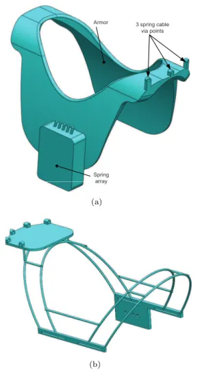
A wearable upper extremity exoskeleton has to be kine-matically compatible with the human arm. The hu-man arm is constructed for dexterity with most of the muscles placed proximally with respect to the joints they actuate to minimize distal mass. Similarly, the fundamental design principle of the exoskeleton is to place springs storing elastic energy close to the body and transfer their effect via flexible cables to the distal parts of the exoskeleton. The exoskeleton has three cuffs, namely, the armor cuff, the elbow upper and lower brackets, which are the so-called hard parts, as shown in Fig.1. A group of cables are routed from the armor cuff to the elbow upper bracket. In the design presented, three cables are used for the shoulder joint, with two cables connecting the elbow upper and lower brackets, as shown in Fig.2.
The armor of the exoskeleton is anchored on the trunk of the user. On the back of the armor, a ca-sing holds all springs. In this spring caca-sing, an array of pre-loaded springs is setup to provide the forces for driving the motion of the arm. The spring box has in-dividual switches for each spring to adjust the pre-load force based on the condition of the patient’s disability. Three via points are designed on the armor to position the cables. The spring forces from the spring array are transferred through the cables to the elbow and shoul-der joint of the human arm.
At the elbow joint, two anchoring nodes are de-signed on the elbow lower bracket, as shown in Fig.2. Two cables linked to two springs from the anchoring point through the two via points on the elbow upper bracket. The force in the cable hereby can provide bal-ance torque for the flexion motion of the elbow. The three anchoring points on the upper bracket are the at-taching nodes for the spring cables which balance the shoulder joint.
3 spring cable via points Armor
Spring array
(a)
(b)
Figure 1: The armor part of the exoskeleton, (a) the profile of the armor part, (b) mechanical structure
3 Modeling of the
Human-exoskeleton System
A human-exoskeleton is a type of biomechanical sys-tem where the exoskeleton works cooperatively with human muscles and nervous system. The interaction between the exoskeleton and the human body deter-mines whether an exoskeleton can implement the de-sired functions. A central issue in the modeling work is thus to simulate the response of the human body subject to external forces/torques exerted by the exo-skeleton.
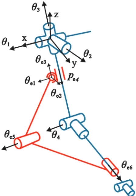
The human-exoskeleton model is constructed by combination of the human arm and the exoskeleton model, schematically shown in Fig. 3. The figure only shows the kinematic structure of the human-exoskeleton model. The blue lines stand for the skele-ton of a human arm, while the red ones represent the
3 spring cable anchoring points
2 spring cable via points Elbow upper
bracket
Elbow lower bracket
2 spring cable anchoring points
(a)
(b)
Figure 2: CAD embodiment of the exoskeleton, (a) the profile of the elbow bracket assembly, (b) me-chanical structure.
exoskeleton. In the human arm model, only the gleno-humeral joint (represented by three revolute jointsθ1,
θ2,θ3) and the elbow flexion jointθ4are supported by
the exoskeleton. The upper elbow bracket is connected to the upper arm through a translation-spherical joint, which allows the bracket to translate freely along the axis of the upper arm. The translational-spherical joint is represented as a spherical joint with three angles θe1, θe2,θe3, and one translational joint pe4. The
up-per and lower elbow brackets are connected to each other through a revolute joint θe5. The attachment
revolute joint θe6. This kind of attachment allows the
lower bracket to rotate around the pronation axis of the forearm.
x
y z
θ
1θ
2θ
3θ
4θ
e1θ
e2θ
e3θ
e5θ
e6p
e4Figure 3: Coordinates and kinematic configuration of the human-exoskeleton system.
$
c1l
2l
1l
1l
e1l
e2$
c2$
c3$
c4$
c5Figure 4: Cables used in the human-exoskeleton system.
The elbow bracket assembly is connected to an ar-mor cuff, which is fixed to the trunk of the human mo-del. The routing of the five cables is shown in Fig. 4 as dashed lines, while the arrows show the direction of cable tension. Three cables $c1, $c2, and $c3 are
anchored from the upper elbow bracket and directed to the armor cuff. These three cables wrap over the glenohumeral joint. With given tensions they can pro-vide supporting torque to the human shoulder. Two cables$c4 and$c5 connect the upper and lower elbow brackets.
3.1 Human Arm Biomechanical Model
In a musculoskeletal model, the human body is mo-deled as a multibody system, in which bones and joints are treated as mechanical links and joints, while mus-cles exert force on the system. It is known that the system is statically indeterminate, because the body contains more muscles than degrees-of-freedom. To re-solve this problem, AMS utilizes optimization to com-pute the muscle and joint forces:
min G(f(M)) s.t. Cf =d∗
fi(M)≥0, i∈ {1, . . . , n
(M)} (1)
where f = [f(R),f(M)] is an n-dimensional vector of
joint reaction forcesf(R)and muscle forces f(M). The
vector d∗ is the external force including gravity and
dynamic forces, and C is a coefficient matrix gene-rated from the arm anatomy and muscle attachments. The objective function G(f(M)) expresses the muscle
recruitment criterion. The possible criteria include soft saturation, min/max and polynomial muscle recruit-ment (Rasmussen et al., 2001). The polynomial crite-rion is adopted as
G(f(M)) =X
i
fi(M)
Ni !p
(2)
whereNiare normalization factors or functions, which
take the form of muscle strength in this work. The powerp controls the synergy of muscles andp= 3 is chosen in this case as it yields good results for most submaximal muscle efforts. The ratiofi(M)/Ni refers
to the muscle activity.
3.2 Paralyzed Muscle
To simulate paralyzed muscles in specific patient cases, certain muscles in the system must be disabled. The equilibrium equation in Eq. (1) can be rewritten as
dj =cj1f1+· · ·+cjifi+· · ·+cjnfn, j= 1. . . m (3)
where dj denotes the jth term of the vectord∗,cji is
the term in the coefficient matrix C, andfi is the ith
If a muscle is disabled, its force is set to zero and the other muscle forces in Eq. (3) must increase to maintain equilibrium.
3.3 Human-exoskeleton Dynamic Model
The human arm skeleton together with the exoskeleton form a closed-loop chain system. The dynamic equa-tion of moequa-tion of each segment is set up with the Newton-Euler equations
miI 0
0 J′ i
¨ qi+
0 ˜ ω′
iJ′iωi′
=gi (4)
whereqi is the vector of assembled coordinates for all
segments, ω′
i is the angular velocity measured in the
body-fixed reference frame. The segment mass is de-noted as mi, and J′i is the inertia tensor with respect
to the centroidal body-frame. The right-hand side,gi,
contains muscle forces, joint reaction forces, and known applied forcesg(app)i . For the system with human arm and the exoskeleton, the external force d∗ in Eq. (1)
can be expressed as
d∗
i =g
(app)
i −
miI 0
0 J′ i
¨ qi−
0 ˜ ω′
iJ′iω′i
(5)
The detailed explanation can be seen in (Damsgaard et al.,2006).
Taking into consideration of spring forces, the right-hand side of the dynamic equation in Eq. (1) is then calculated by
di=d∗i +E(q)Ttc (6)
where vector tc contains the tensions of the
incorpo-rated springs. The coefficient matrix E is generated from the installation of springs in the exoskeleton and the exoskeleton attachment to the arm.
The muscle recruitment in Eq. (1) then becomes min G(f(M))
s.t. Cf =d (7)
fi(M)≥0, i∈ {1, . . . , n
(M)}
3.4 Spring Tension
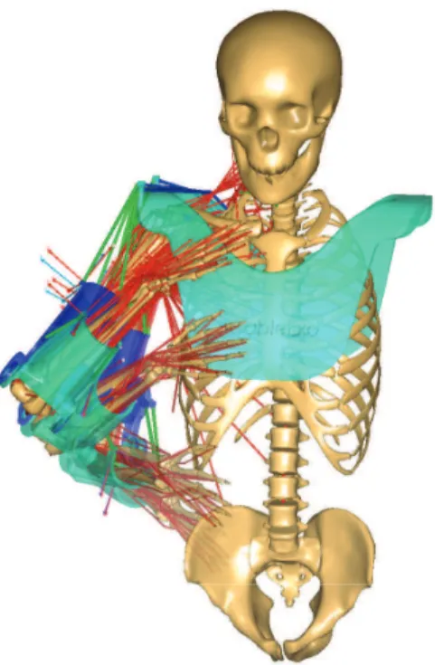
As shown in Fig.5, the green lines represent the cables for transferring forces. In this design, two springs are used to drive the elbow joint and three springs to drive the shoulder joint. The cable tension generated by the spring is thus calculated by
tc=tpre+k∆l (8)
with k=
kgh1 0
kgh2
kgh3
kel1
0 kel2
(9)
where tpre denotes pre-load of the spring, k is the
spring stiffness matrix. ∆lis the vector of the spring elongations.
The pre-load tension of the spring is
tpre=k lpre (10)
withlprebe the pre-load length of the spring.
Combining Eqs. (8) and (10), the cable tension can be calculated by
tc=k(lpre+ ∆l) (11)
Here, we divide the elongation of the spring into two parts. The reason is that at any initial state of the exoskeleton, some cable(s) should be taut to compen-sate the weight of the arm. The variation of the spring length ∆lonly changes according to the positions of the attaching points. The pre-load lengthlpreprovides us
a way to manipulate the pre-load tension with respect to different load cases.
4 Implementation of
Human-exoskeleton Model
The motion of the musculoskeletal model is based on motion capture data. Brachial plexus injury, arising typically from falls and traffic accidents, is selected as the patient case of the exoskeleton (Glanze et al.,1990).
4.1 Implementation in AnyBody
Figure 5: A wearable spring-loaded cable-driven exo-skeleton with a musculoskeletal model.
The musculoskeletal right arm model is derived from the repository models (Version 1.4) in AnyBody. The whole musculoskeletal model is comprised of 39 joints and 134 muscles.
Several special configurations are made to the human-exoskeleton model in AnyBody:
1. The exoskeleton does not support the wrist joint and the pronation of the forearm, even though these are affected by the paralysis depending on the location of the lesion. To focus the design on the supported DoFs, the biomechanical mo-del supports the wrist flexion, wrist abduction and the elbow pronation artificially by reaction forces. This corresponds to supporting the wrist joint and elbow pronation with orthotics.
2. In the modeling, the forearm is allowed to pronate/supinate inside the elbow lower bracket to mimic the significant motion of the skin above the bones. Support of the forearm prona-tion/supination would require development or an interface between the exoskeleton and the forearm capable of supporting torsion.
3. The human arm model is used to simulate particu-lar lesion cases. Each piece of muscle in the arm is linked to a corresponding nerve as explained in the next section. The muscle can be enabled/disabled depending on the lesion type.
4.2 Design Case
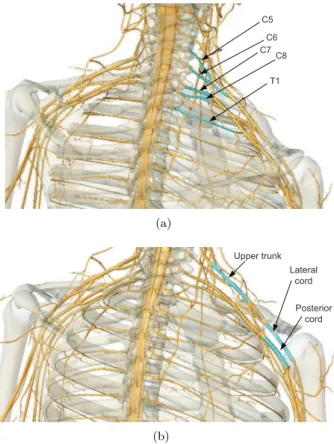
The brachial plexus is a network of nerves that trans-fers signals from the spinal cord to the shoulder and upper limb. These nerves root from the fifth to the eighth cervical (C5-C8), and first thoracic (T1) spinal nerves, as illustrated in Fig.6(a). They innervate the muscles and skin of the chest, shoulder and upper limb. Injuries of brachial plexus, or lesions, often caused by trauma conditions such as traffic accidents can have serious effect on the mobility of limbs (Shveiky et al.,
2010).
The branches of the brachial plexus and their associ-ated muscles are listed in Table1, sorted with respect to their roots. The spinal nerves and their cord related to brachial plexus are shown in Fig.6(a)and Fig.6(b).
C5
C6 C7
C8
T1
(a)
Upper trunk Lateral
cord
Posterior cord
(b)
Figure 6: The spinal nerve cords of the nervous system.
4.3 Motion of a Human Arm
In order to actuate the musculoskeletal human arm model, realistic motion data is needed. In this work, a customized motion capture system is built by two KinectT M sensors. A motion of picking up a cup and
drinking is captured within 3 seconds, as shown in Fig.7. The payload is 0.5kg carried by the hand.
Table 1: Brachial plexus branches associated to different arm muscles (Moore and Agur, 2007). No. Nerve Muscles
1 C5 deltoid, teres minor, triceps brachii, supinator, anconeus, the extensor muscles of the forearm, brachioradialis, subscapularis, teres major, pectoralis major, coracobrachialis, brachialis, biceps brachii, serratus anterior, rhomboid muscles, levator scapulae
2 C6 deltoid, teres minor, triceps brachii, supinator, anconeus, the extensor muscles of the forearm, brachioradialis, subscapularis, teres major, pectoralis major, coracobrachialis, brachialis, biceps brachii, serratus anterior, latissimus dorsi 3 C7 triceps brachii, supinator, anconeus, the extensor muscles of the forearm,
bra-chioradialis, latissimus dorsi, pectoralis major, coracobrachialis, brachialis, bi-ceps brachii, serratus anterior
4 C8 triceps brachii, supinator, anconeus, the extensor muscles of the forearm, bra-chioradialis, latissimus dorsi
5 T1 triceps brachii, supinator, anconeus, the extensor muscles of the forearm, bra-chioradialis
6 posterior cord
deltoid, teres minor, triceps brachii, supinator, anconeus, the extensor muscles of the forearm, brachioradialis, subscapularis, teres major, latissimus dorsi 7 lateral
cord
pectoralis major, coracobrachialis, brachialis, biceps brachii 8 upper
trunk
supraspinatus, infraspinatus
9 root serratus anterior, rhomboid muscles, levator scapulae
Figure 7: The motion of picking up a cup and drinking in 3 seconds.
are depicted in Fig. 8. As the exoskeleton does not support the motion of the elbow pronation and the wrist joint, only the other four joints motion of the human arm are captured and utilized in the simulation.
0 0.5 1 1.5 2 2.5 3
−40 −20 0 20 40 60 80 100 120 140
Time [s]
Joint Angle [deg]
GHFlexion GHRotation GHAbduction ElbowFlexion
Figure 8: Joint angles in the motion of lifting a cup. (GH denotes the glenohumeral joint.)
0 0.5 1 1.5 2 2.5 3 0.065
0.07 0.075 0.08 0.085 0.09 0.095
Time [s]
Maximal Muscle Activity
Figure 9: Muscle activity in the motion of picking up a cup.
4.4 Maximal Muscle Activation
The simulation of the brachial plexus injury is catego-rized according to its root and origin. Muscle activity is defined as the ratio between the instantaneous mus-cle force and the instantaneous musmus-cle strength. When the muscle activity of any muscle exceeds 1, that mus-cle has insufficient strength to complete the required motion. To allow the simulation to complete in cases of inadequate muscle strength, weak artificial muscles have been added to the joints, thus allowing all the cases of lesions to be simulated, albeit in some cases with very high activation levels.
The maximal muscle activation (MMACT) is calculated for different nerve lesion conditions. The arm muscles are categorized into groups, as shown in Table1. For example, if the nerve root C7 has a lesion, all the muscles related to C7 will be paralyzed. The calculated maximal MMACTs of the different nerve le-sions are shown in Fig. 10. Note that the case BASE refers to the motion without any nerve lesion.
It is found that paralyzing nerve C5 or C6 will lead to very high MMACT. This is reasonable as these le-sions paralyze most of the functional muscles in the upper arm and shoulder. The high required muscle ac-tivity indicates that if there is lesion at C5 or C6, it might be hard to restore motion with a purely passive exoskeleton. The maximal MMACTs of nerve lesions C8, T1, Posterior cord, Lateral cord, Upper trunk and Root do not exceed 1, such that these nerve lesions do not need the assistance of the exoskeleton. The case C7 with a maximal MMACT of 25.1 is selected for in-vestigation as to be described in Sec. 6.
5 Design Optimization
With the model of the human-exoskeleton system, we are able to simulate and analyze the muscle activity for given motion and design parameters. As the spring-cable-driven exoskeleton utilizes five springs in the
pro-BASE C5 C6 C7 C8 T1 PosteriorLateral Trunk Root 0
0.1 0.2 0.3 0.4 0.5 0.6 0.7 0.8 0.9 1
Maximum Muscle Activity
0.09
369.00 95.70 25.10
0.27 0.27 0.27 0.25
0.14 0.79
Figure 10: Maximal MMACT of different nerve lesion cases.
posed design, for which the stiffness has to be selected to provide assistive function, we further developed an optimization method to select proper spring stiffness. In the optimization problem, the objective of the exo-skeleton is to reduce the maximal MMACT over the entire motion. The objective function is defined as
min
x f(
x) = max
t (
max
i (
fi(M)
Ni ))
(12) x = [kgh1, kgh2, kgh3, kel1, kel2]
s.t. min G(f(M)) Cf =d
fi(M)≥0, i∈ {1, . . . , n
(M)}
where the design variables x refer to the five springs linked to the cables $c1, $c2, $c3, $c4 and $c5 in Fig. 4. The optimization problem is solved by the Complex method (Box,1965;Guin,1968) with its im-plementation in AnyBody. This optimization problem is wrapped around the full inverse dynamic analysis of the model. In each iteration, the maximal MMACT is calculated over the motion duration t after inverse dynamics is completed.
The overall structure of simulation and design opti-mization is illustrated in Fig.11.
6 Simulation and Optimization
Results
6.1 Optimization Results
Complex method
Initial exoskeleton
design
Human-exoskeleton model
Execute kinematic and dynamic
simulation
Minimize MMACT Optimal
exoskeleton Converge ?
No Update design
variables
Yes
Figure 11: Routine of design optimization.
Complex method. The objective convergence tolerance is 0.001, and the convergence tolerance for the design variables is 0.1. The optimization reduces the maxi-mal MMACT from 25.1 of the case without assistance to 0.58 with the exoskeleton. The convergence of the maximal MMACT is plotted in Fig.12.
0 100 200 300 400 500 600 700 0
10 20 30 40 50 60 70 80
Iteration Number
Maximal MMACT
0.58
Figure 12: Optimization of the maximal MMACT. In the optimization case, all the pre-load lengths of the five springs are set tolpre= 0.06m. The optimal
design variables are obtained as
x= [1473.4,0.3,0.03,102.0,1979.0]N/m The iteration history of the stiffness coefficients of the five springs are plotted in Fig. 13, which can be used to select springs for the exoskeleton.
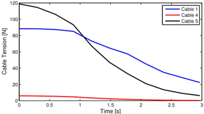
6.2 Cable Tension
The optimal spring stiffness kgh2 = 0.3 N/m and
kgh3 = 0.03 N/m for cables 2 and 3 are negligible.
The cable tensions for the other three springs during the motion of picking up a cup are plotted in Fig.14.
0 100 200 300 400 500 600 700 −500
0 500 1000 1500 2000 2500
Iteration Number
Spring Stiffness [N/m]
k gh1 k
gh2 k
gh3 k
el1 k
el2
Figure 13: Convergence of the stiffness coefficients.
Cable 1 is the only one for supporting the glenohumeral joint. As cable 1 compensates almost the weight of the whole arm and the exoskeleton elbow brackets, it re-quires the highest tension. The tensions of cables 4 and 5 fall down to zero in the later stage of the motion as the two springs are returning to their slack states. Since the cable can only pull, the cable tensions will be always larger than zero.
0 0.5 1 1.5 2 2.5 3
0 20 40 60 80 100 120
Time [s]
Cable Tension [N]
Cable 1 Cable 4 Cable 5
Figure 14: Cable tension on the optimal exoskeleton.
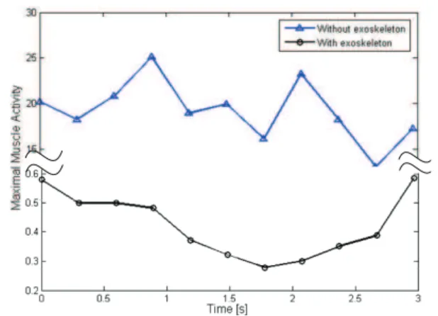
6.3 Arm Reactions
Figure 15: The comparison of the MMACT after optimization.
7 Discussions
The result of the combined simulation and optimiza-tion process was very satisfactory in the sense that the simulated model is enabled by the exoskeleton to per-form the desired task. However, the analysis is based on an ideal situation in which the nerve lesion and its precise effect on the muscles are known. Actual patient cases may be more complex or less well-defined. Also, the model does not take dissipative effects such as fric-tion in the cables and joints, visco-elastic effects in the interfaces with soft tissue or sensitivity of the solution to design tolerances into account. It is therefore likely that significant practical experimentation and design maturation are necessary before exoskeletons of this type reach their full potential for specific patients with specific lesions.
The passive type of exoskeleton has the distinct ad-vantage of simplicity over its active counterparts, and the complex control, safety and power supply issues fo-llowing from the use of electrical motors and controllers are eliminated. Due to the absence of rigid links around the shoulder joint, the exoskeleton does not constrain the free motion of the shoulder.
The optimization results show that only three of the springs are exploited for this patient and movement case. However, it does not mean that the other two springs are redundant; they become useful for other movements. The selected arm motion for the design optimization is quasi-static, and dynamic effects may simultaneously limit and extend the usability of the exoskeleton. Users of advanced orthotics are often able to extend their control beyond the available support by using dynamic effects to their advantage. On the other hand, the simulation provides no guarantee that the proposed exoskeleton is applicable to fast arm motion.
8 Conclusions
An approach to design exoskeletons through biome-chanics simulation was proposed. It involves an inte-grated human-exoskeleton model to simulate and opti-mize the wearable exoskeleton. The model can simu-late the biomechanics of the human arm in the presence of partial paralysis. The integration of the human and exoskeleton models reveals the interaction between two individual models, and help to optimize the exoskeleton with respect to the performance of the human model. The specialized model can be used to design different types of exoskeletons based on different neuromuscular injuries. A spring-loaded and cable-driven exoskeleton was designed by the developed approach.
The approach provides a convenient and efficient way to design and develop wearable exoskeletons. Through biomechanics simulations, many parameters of exo-skeletons can be obtained and evaluated based on the reactions of the human body model. Nevertheless, de-sign simulation alone is insufficient so a prototype will be built and experiments with real patients’ activities of daily living will be conducted. The results of these efforts will likely lead to modifications towards the final design.
Acknowledgements
The project belongs to a strategic platform for re-search and innovation, namely, Patient @ home, which is funded by The Danish Agency for Science, Techno-logy and Innovation.
References
Agrawal, S. K., Dubey, V. N., Gangloff, J. J., Brackbill, Y., Mao, Y., and Sangwan, V. Design and optimiza-tion of a cable driven upper arm exoskeleton. Jour-nal of Medical Devices, 2009. 3:031004–1–031004–8. doi:10.1115/1.3191724.
Bai, S. and Rasmussen, J. Modelling of physical human-robot interaction for exoskeleton designs. In J. C. Samin and P. Fisette, editors, Proc. of Multi-body Dynamics 2011, ECCOMAS Thematic Confer-ence. Brussels, Belgium, pages 1–7, 2011.
Box, M. J. A new method of constrained optimization and a comparison with other methods. Computer Journal, 1965. 8:42–52. doi:10.1093/comjnl/8.1.42. Carignan, C., Tang, J., and Roderick, S. Development
training. InProc. of IEEE/RSJ Inter. Conf. on In-telligent Robots and Systems. pages 3697–3702, 2009. doi:10.1109/IROS.2009.5354834.
Damsgaard, M., Rasmussen, J., Christensen, S. T., Surma, E., and Zee, M. d. Analysis of muscu-loskeletal systems in the Anybody Modeling System.
Simulation Modelling Practice and Theory, 2006. 14:1100–1111. doi:10.1016/j.simpat.2006.09.001. Gallagher, W., Ding, M., and Ueda, J. Relaxed
indi-vidual control of skeletal muscle forces via physical human-robot interaction. Multibody System Dynam-ics, 2013. 30:77–99. doi:10.1007/s11044-013-9362-y. Garrec, P., Friconneau, J. P., Measson, Y., and Perrot, Y. ABLE, an innovative transparent exoskeleton for the upper-limb. InProc. of IEEE/RSJ Inter. Conf. on Intelligent Robots and Systems. pages 1483–1488, 2008. doi:10.1109/IROS.2008.4651012.
Glanze, W. D., Anderson, K. N., and Anderson, L. E.
Mosby’s Medical, Nursing, and Allied Health Dic-tionary (3rd ed.). The C.V. Mosby Co., St. Louis, Missouri, USA, 1990.
Guin, J. A. Modification of the complex method of constrained optimization. Computer Journal, 1968. 10:416–417. doi:10.1093/comjnl/10.4.416.
Haumont, T., Rahman, T., Sample, W., King, M. M., Church, C., Henley, J., and Jayakumar, S. Wilm-ington robotic exoskeleton: a novel device to main-tain arm improvement in muscular disease. Jour-nal of Pediatric Orthopedics, 2011. 31(5):e44–e49. doi:10.1097/BPO.0b013e31821f50b5.
Lee, L. F., Narayanan, M. S., Kannan, S., Mendel, F., and Krovi, V. N. Case studies of musculoskeletal-simulation-based rehabilitation program evaluation.
IEEE Transactions on Robotics, 2009. 25(3):634– 638. doi:10.1109/TRO.2009.2019780.
Lenzi, T., Vitiello, N., Rossi, S. M. M. D., Roccella, S., Vecchi, F., and Carrozza, M. C. NEUROExos: a variable impedance powered elbow exoskeleton. In
Proc. of IEEE Inter. Conf. on Robotics and Au-tomation. Shanghai, China, pages 1419–1426, 2011. doi:10.1109/ICRA.2011.5979866.
Lo, H. S. and Xie, S. Q. Exoskeleton robots for upper-limb rehabilitation: State of the art and future prospects. Medical Engi-neering & Physics, 2012. 34(3):261–268. doi:10.1016/j.medengphy.2011.10.004.
Mao, Y. and Agrawal, S. K. Design of a cable-driven arm exoskeleton (CAREX) for neural rehabilitation.
IEEE Transactions on Robotics, 2012. 28(4):922– 931. doi:10.1109/TRO.2012.2189496.
Moore, K. L. and Agur, A. M. Essential Clinical Anatomy (3rd ed.). Lippincott Williams & Wilkins, Baltimore, USA, 2007.
Nef, T., Guidali, M., and Riener, R. ARMinIII - arm therapy exoskeleton with an ergonomic shoulder ac-tuation. Applied Bionics and Biomechanics, 2009. 6(2):127–142. doi:10.1080/11762320902840179. Perry, J. C., Rosen, J., and Burns, S.
Upper-limb powered exoskeleton design. IEEE/ASME Transactions on Mechatronics, 2007. 12(4):408–417. doi:10.1109/TMECH.2007.901934.
Rahman, T. and et al. Passive exoskeletons for assisting limb movement. Journal of Rehabilita-tion Research & Development, 2006. 43(5):583–590. doi:10.1682/JRRD.2005.04.0070.
Rasmussen, J., Damsgaard, M., and Voigt, M. Muscle recruitment by the min/max criterion: A compara-tive numerical study.Journal of Biomechanics, 2001. 34(3):409–415. doi:10.1016/S0021-9290(00)00191-3. Ren, Y., Park, H. S., and Zhang, L. Q.
Develop-ing a whole-arm exoskeleton robot with hand open-ing and closopen-ing mechanism for upper limb stroke rehabilitation. In Proc. of IEEE Inter. Conf. on Rehabilitation Robotics. pages 761–765, 2009. doi:10.1109/ICORR.2009.5209482.
Shveiky, D., Aseff, J. N., and Iglesia, C. B. Brachial plexus injury after laparoscopic and robotic surgery.
The Journal of Minimally Invasive Gynecology, 2010. 17(4):414–420. doi:10.1016/j.jmig.2010.02.010. Vertechy, R., Frisoli, A., Dettori, A., Solazzi, M., and Bergamasco, M. Development of a new exoskeleton for upper limb rehabilitation. In Proc. of IEEE/RSJ Inter. Conf. on Intelli-gent Robots and Systems. pages 188–193, 2009. doi:10.1109/ICORR.2009.5209502.
Wolbrecht, E. T., Chan, V., Reinkensmeyer, D. J., and Bobrow, J. E. Optimizing compliant, model-based robotic assistance to promote neurorehabili-tation. IEEE Transactions on Neural Systems and Rehabilitation Engineering, 2008. 16(3):286–297. doi:10.1109/TNSRE.2008.918389.