Solar Panel Mathematical Modeling Using Simulink
Chandani Sharma, Anamika Jain
Research Scholar, Electronics & Communication Engg. Graphic Era University, Dehradun Uttrakhand, India HOD, Electronics & Communication Engg. Graphic Era University, Dehradun Uttrakhand, India
Abstract
For decades, electricity is a key driver of socio-economy development. Nowadays, in the context of competition there is a direct relationship between electricity generation and sustainable development of the country. This paper presents distinct use of a Photovoltaic array offering great potential as source of electricity. The simulation uses One-diode equivalent circuit in order to investigate I-V and P-V characteristics. The GUI model is designed with Simulink block libraries. The goals of proposed model are to perform a systematic analysis, modeling and evaluation of the key subsystems for obtaining Maximum Power Point of a solar cell. Effect of increasing number of cells is described at Standard Test Conditions by mathematical modeling of equations. It is desirable to achieve maximum power output at a minimum cost under various operating conditions.
Index
Terms
— Photovoltaic array, GUI model, Simulink, Maximum Power Point, Standard Test Conditions.I.
Introduction
With affordable costs of solar energy, alternative energy revolution has started and is gradually picking up speed. A massive transformation has begun resulting number of attractive opportunities for entrepreneurs. Photovoltaic System uses one or more solar modules or panels to convert solar energy to electrical energy. Photovoltaic Module refers to number of solar cells connected in both series and parallel connections to achieve the desired output. Solar Cells are the building blocks of a Photovoltaic array. These are made up of semiconductor materials like silicon etc. A thin semiconductor wafer is specially treated to form an electric field, positive on a side and negative on the other. Electrons are knocked loose from the atoms of the semiconductor material when light strikes upon them. If an electrical circuit is made attaching a conductor to the both sides of the semiconductor, electrons flow will start causing an electric current.
BASIC SOLAR CELL
A single solar cell is constructed using a resistance Rs that is connected in series with a parallel combination of a Current source consisting of single diode with a shunt resistance structure RSH. Solar cell uses photoelectric effect converting solar energy
directly into electric energy. Thus electrical
characteristic like current, voltage and resistance vary when light is incident upon it. This results in generation of electric current without being attached to any external voltage source. To obtain power consumption, external load is attached.
The equations prior to solar cell construction include equations mentioned below:
Thermal Voltage Equation
VT = kBTOPT/q (1)
Diode Current Equation
ID= Np IS [e (V/Ns) + (IRs/Ns)/N VT C -1] (2)
Load Current Equation
IL = IPh Np- ID-ISH (3)
Photocurrent Equation
IPh= [ki (TOPT -TREF) +ISC] IRR (4)
Shunt Current Equation
ISH = (IRS+V)/RSH (5)
Reverse Saturation Current
IS = [IRS (TOPT/TREF) 3 *q2Eg/NkB *e (1/TOPT-1/TREF) (6)
Reverse Current Equation
IRS= ISC / [e (q VOC/kiCTOPT)-1] (7)
Output Power
P=VI (8)
Where:
VT: Thermal Voltage (V). V: Operating Voltage (V). VJ: Junction Voltage (V).
VOC: Open Circuit Voltage (21.1V).
IPh: Photocurrent function of irradiation and junction temperature (5 A).
IS: Reverse Saturation Current of Diode (2*10-4 A). ISC: Short Circuit Current (3.8A).
I: Cell Output Current (A).
TREF: Reference Operating Temperature of Cell (25 °C).
TOPT: Operating Temperature of Cell (°C). RSH: Shunt Resistance of Cell (360.002 Ω). RS: Series Resistance of Cell (0.18Ω). Eg: Energy Band Gap (1.12 eV).
N: Ideality Factor (1 for low level minority carrier injection, 1.36 for solar cell and 2 for high level both carriers injection).
kB: Boltzmann constant (1.38 × 10⁻²³ J/K). ki: Current Proportionality constant (2.2*10-3). kv= Voltage Proportionality constant (73*10-23). q: Electron charge (1.602 × 10⁻¹⁹ C).
Ns: No. of cells in series. Np: No. of cells in parallel. G: Irradiance (1000W/m2). C= No. of cells in Module.
By creating electrical dc equivalent model of solar cell, behavior of a solar cell is determined. An ideal solar cell may be modeled using a current source in parallel with diode. But generally in practice no solar cell is ideal, so an equivalent small series resistance and appropriate shunt resistance component are added to the model. Ideally it is constructed such that it follows STC (Standard Test Conditions) with values of constants equal to the ones mentioned above.
The dc equivalent circuit of a solar cell is shown below:
FIG1: DCEQUIVALENTMODELOFSOLAR
CELL
From the equivalent circuit it is evident that the current produced by the solar cell is equal to that produced by the current source IPNP, minus that which flows through the diode ID, minus that which flows through the shunt resistor ISH as described:
IL= Iph Np-ID-ISH
The current through these elements is governed by the voltage across them:
VJ =V+IRS
Diode Current is governed by Shockley’s equation
given below:
Id= Np IS [e (V/Ns) + (IRs/Ns)/N VTC -1]
By Ohm’s Law, the current through the shunt resistor is given as
ISH= VJ /RSH ISH = (V+IRS)/RSH
Substituting these equations in equation to determine load current
IL= Iph Np - Np IS [e (V/Ns) + (IRs/Ns)/N VT C -1] - (IRS+V)/RSH
Thus given a particular operating
voltage V the equation may be solved to determine the operating current IL at that voltage.
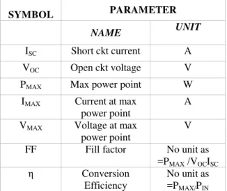
Apart from theory explained above several parameters contribute to working of solar cell in obtaining maximum power output and hence determination of efficiency. These are listed below:
SYMBOL PARAMETER
NAME UNIT
ISC Short ckt current A
VOC Open ckt voltage V
PMAX Max power point W
IMAX Current at max
power point
A
VMAX Voltage at max
power point
V
FF Fill factor No unit as
=PMAX /VOCISC
η Conversion
Efficiency
No unit as =PMAX/PIN
TABLE1: VARIOUSFACTORSSTUDIEDIN
DESCRIBINGSOLARCELL
While describing Solar Cell, ISC, short-circuit current is the largest current which may be drawn from the solar cell at zero voltage obtained due to the generation and collection of light-generated carriers. The open-circuit voltage, VOC is the maximum voltage available from a solar cell corresponding to the amount of forward bias on the solar cell due to zero current.
In general, the maximum power delivered from a solar cell is PMAX=IMAXVMAX generated at its output, not necessarily at STC. However, ideal maximum power corresponds to ISC and VOC, i.e. the product of open circuit voltage and short circuit current. Thus a factor known as Fill Factor, FF, describing experimental output in conjunction with ISC and VOC is calculated. FF = PMAX/VOCISC.
Graphically FF is a measure of the squareness of the solar cell fitting in the Current Voltage IV curve. The conversion efficiency η of solar cells is calculated as the ratio between the generated maximum power, PMAX and the incident power, PIN using Power Voltage PV curve. η = VOCISCFF//PIN.
FIG 2: IV CHARACTERISTIC CURVE OF SOLAR CELL
II.
SIMULINK MODELLING
Equations described in introduction are modeled to obtain IV and PV Characteristics of a single diode solar cell model.
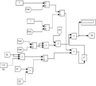
The ideal characteristics of a solar array are verified at standard test conditions. Similar conditions are designed in Simulink. It is MATLAB programming language for simulating and analyzing multi domain functions or systems. Complete subsystem is obtained as given below:
FIG3: COMPLETESUBSYSTEM
III.
SUBSYSTEM EQUATIONS
MODELLING
1. Thermal Voltage Equation
VT = kBTOPT/q
The thermal voltage equation is used to describe average energy of electrons diffused in solar cell moving randomly at given temperature. VT is about 25.85 mV at 300K.
FIG4: THERMALVOLTAGEEQUATION
MODEL
2. Diode Current Equation
Id= Np Is [e (V/Ns) + (IRs/Ns)/N VT C -1]
The diode equation gives an expression for the current through a diode as a function of voltage.
FIG5: DIODECURRENTEQUATIONMODEL
3. Load Current Equation
IL = IPh Np-ID-ISH
IL is described by difference of current across current source and diode.
FIG 6: LOAD CURRENT EQUATION MODEL
4. Photo Current Equation
IPh = [Ki (TOPT-TREF) +ISC] IRR
Radiant power from sun results in current flow through solar cell. Since thermal excitation of minority carriers contribute to current flow, reverse saturated current also affects Photo Current
Equation. The temperature dependence of
photocurrent is measured for reference cell and Operating cell temperature.
FIG 7: PHOTO CURRENT EQUATION MODEL
5. Shunt Current Equation
ISH = (IRS+V)/RSH
manufacturing defects in values of series and shunt resistance. Solar cell behaves neither as current source nor as a voltage source. Since losses caused by series resistance are given by PLOSS=IV=I2RS, they increase quadratically with photocurrent. Similarly, current diverted through the shunt resistor increases causing the voltage-controlled portion of the IV curve to sag towards origin.
FIG 8: SHUNT CURRENT EQUATION MODEL
6. Reverse Saturation Current
IS= [IRS (TOPT/TREF)3 *q2Eg/NkB * e(1/TOPT-1/TREF)]
The reverse saturation current also known as leakage current IS, is the current that flows in the reverse direction when the diode is reverse biased. The reverse saturation current IS is dependent on temperature, diffusion constants, Energy Band gap, ideality factor, Boltzmann constant as in equation. IS is a measure of the recombination in a device. Itincreases as T increases and decreases as material quality increases.
FIG9: REVERSESATURATIONCURRENT
EQUATIONMODEL
7. Reverse Current Equation
IRS= ISC/ [e (q V
OC /K
B CT
OPTN )
-1]
Dependence of reverse saturation current is considered relative to open circuit voltage and
operating temperature in order to detect possible change in reverse saturation current equation.
FIG10: REVERSECURRENTEQUATION
MODEL
8. Output Power
P=VI
When packaged after connection panel is used for electricity generation and supply. Various commercial and residential applications give output power dependent on operating input voltage and current.
FIG 11: OUTPUT POWER EQUATION MODEL
IV.
RESULTS
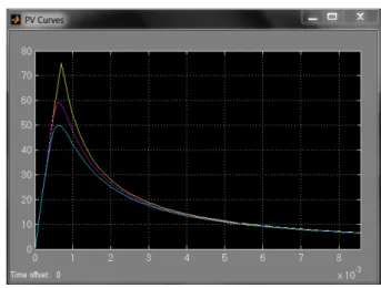
Characteristics plots of IV and PV curves result maximum output for single solar cell at STC. However on increasing number of cells, output decreases.
It is due to the fact that change in light intensity incident on a solar cell changes by increasing number of cells causing solar cell parameters to change.
These parameters result change of series Resistance RS and Shunt Resistance RSH causing change in VI and PV Characteristics. This affects short-circuit current ISC, open-circuit voltage VOC, Fill Factor FF, and Efficiency η to vary with varying quantity of cells.
FIG 12: IV GRAPHS FOR MULTIPLE SOLAR CELLS
FIG 13: PV GRAPHS FOR MULTIPLE SOLAR CELLS
FIG 14: IV SCOPE OUTPUT FOR MULTIPLE SOLAR CELLS
FIG 15: PV SCOPE OUTPUT FOR MULTIPLE SOLAR CELLS
The light intensity on a solar cell is called the number of suns or Irradiance G, where 1 sun corresponds to standard illumination at about 1000 W/m2. The deviating IV and PV Characteristics shift towards origin decreasing output.
A comparison related to single solar cell, 36, and 72 solar cells have been shown above. A PV module designed to operate under 1 sun conditions is called a concentrator but practically reflectors having large surface area are used. Commercially 36 and 72 solar cell based panel is used on mounting for fixed structure used in solar street lighting or heating applications for domestic uses.
V.
FUTURE WORK
There emerges an important need to converge distributed Maximum Power Point when operating multiple modules in parallel for use in MRDEG Multisource Renewable Distributed Energy Generation Systems (MRDEG). As such different Control Systems are desired to maintain same MPP irrespective of variations as described by maximum output of single solar cell even when using multiple solar cells.
REFERENCES
[1] Tarak Salmi, Mounir Bouzguenda, Adel
Gastli, Ahmed Masmoudi
“MATLAB/Simulink Based Modelling Of Solar Photovoltaic Cell”, International
Journal of Renewable Energy Research Tarak Salmi Et Al., Vol.2, No.2, 2012.
[2] Dr.P.Sangameswar Raju, Mr. G.
Venkateswarlu, “Simscape Model Of
Photovoltaic cell”, International Journal of
Advanced Research in Electrical,
Electronics and Instrumentation
Engineering, Vol. 2, Issue 5, May 2013.
[3] URL
[4] URL http://photovoltaic model in MATLAB/simulink.
[5] Savita Nema, R.K.Nema, Gayatri Agnihotri,
“Matlab / simulink based study of
photovoltaic cells / modules / array and their
experimental verification”, International Journal of Energy and Environment, Volume 1, Issue 3, 2010 pp.487-500. [6] Pavels Suskis, Ilya Galkin, “Enhanced
Photovoltaic Panel Model for MATLAB-Simulink Environment Considering Solar
Cell Junction Capacitance”, Industrial Electronics Society, IECON 2013 - 39th Annual Conference of the IEEE.
[7] Islam, M.A, Mohammad, N. Khan, P.K.S,
“Modeling and performance analysis of a generalized photovoltaic array in matlab”
Joint International Conference in 2010 on Power Electronics, Drives and Energy Systems by IEEE.
[8] Shekoofa O, Taherbaneh, M, “Modelling of silicon solar panel by matlab/simulink and evaluating the importance of its parameters
in a space application” 3rd International