By:
Nelson Bruno Tavares Ferreira
____________________________________
Supervisor
Prof. Doutor José Torres
Co-Supervisor
Eng. César Toscano
The possibility of displaying high performance 3D accelerated graphics in the browser is seen as an obstacle to the conversion of applications to the web. The release of WebGL made Web3D gain new strength to overcome that obstacle. Architecture, Engineering and Construction (AEC) tools are a type of applications that could benefit with this advance. In the AEC industry, there is a standard candidate for Building Information Modelling (BIM), called Industry Foundation Classes (IFC). This data model promotes interoperability between AEC tools, giving a common format to the applications.
This work comes from the need of redesigning a legacy application that allows the user to design, display and calculate building structures. Focusing on the displaying of building structures, this work merges IFC and WebGL into an application, to replicate in a modern way the legacy application capabilities.
This is done by developing a server module that processes the IFC data model and a client module that displays that model in a WebGL environment.
A possibilidade de visualização de gráficos acelerados 3D de alto desempenho no navegador ainda é visto como um obstáculo na migração de aplicações para a web. O lançamento do WebGL fez o Web3D ganhar uma nova força para superar esse obstáculo. As ferramentas de Arquitetura, Engenharia e Construção (AEC) são um tipo de aplicações que podem beneficiar com este avanço. Na indústria AEC, há um candidato a padrão para Building Information Modelling (BIM), chamado de Industry Foundation Classes (IFC). Este modelo de dados promove a interoperabilidade entre as ferramentas de AEC, fornecendo um formato comum às aplicações.
Este trabalho surge da necessidade de redesenhar uma aplicação legada que permite ao o utilizador projetar, visualizar e calcular estruturas de edifícios. Focando na visualização de estruturas de edifícios, este trabalho funde o IFC e o WebGL numa aplicação, para replicar de forma moderna as capacidades da aplicação legada.
Isto é feito através do desenvolvimento de um módulo de servidor que processa o modelo de dados IFC e um módulo de cliente que mostra esse modelo num ambiente
WebGL.
First of all would to thank my mother (Maria do Carmo), stepfather (Domingos José) and my grandfather (Carlos Alberto) for giving me the opportunity of going to the university, for the motivation and financial support. Thanks also to the rest of my family that cared for my well being and education.
A special thanks to my girlfriend Betty, who always supported me in good and bad moments.
Thanks to my friends Nuno Marques, Filipe Barbosa, Bruno Cardoso, Bruno Silva, Ana Nunes and all the CK members who I could always count on.
Thanks to my supervisors Eng. César Toscano for the patience during the project and Prof. José Torres during the elaboration of this document. Thanks also to Engº José Carlos Lino and Dr. Manuel Teixeira from NewtonConsultores de Engenharia, for their support.
A thanks also to all the teachers of the Computer Engineering department of Universidade Fernando Pessoa and all my colleges from INESC Porto.
3D – Three Dimensions
AEC - Architecture, Engineering and Construction
AECO – Architecture, Engineering, Construction and Operation
ANGLE – Almost Native Graphics Layer Engine
API – Application Programming Interface
ASCII – American Standard Code for Information Interchange
BIM – Building Information Model
CAD – Computer-Aided Design
COLLADA – COLLAborative Design Activity
CPU – Computer Processing Unit
DIS – Distributed Interactive Simulation
DLL – Dynamic Link Library
DOM – Document Object Model
EMF – Eclipse Modelling Framework
GLSL – OpenGL Shading Language
HTML – HyperText Markup Language
HTTP – HyperText Transfer Protocol
IDE – Integrated Development Environment
IEC – International Electrotechnical Commission
IFC – Industry Foundation Classes
ISO – International Organization for Standards
J3D – Java 3D
JRE – Java Runtime Environment
JSON – JavaScript Object Notation
OS – Operating System
RIA – Rich Internet Applications
UML – Unified Modelling Language
VBO – Vertex Buffer Objects
VRML – Virtual Reality Modelling Language
X3D – Extensible 3D Graphics
Abstract...V Resumo...VI Acknowledgements...VIII Acronyms...IX Index...XI Index of Figures...XIII Index of Tables...XV
1.Introduction...16
1.1.PacPórticos Overview...19
1.2.Objectives...20
1.3.Document Structure...22
2.State of the art...23
2.1 Web3D...23
2.1.1 WebGL...24
2.1.2 X3D...29
2.1.3 Adobe Flash...32
2.1.4 J3D...33
2.1.5 Unity...33
2.1.6 Microsoft Silverlight...34
2.2 BIM IFC...34
2.3 Vaadin Framework...38
2.4 Related Work...40
2.5 Summary...41
3.Method...42
3.1 Conception...42
3.1.1 Server-Side Module...44
3.1.1.1 IFC Processing and Model Creation...45
3.1.2 Client-Side Module...47
3.1.2.1 IFC WebGL Widget...47
3.2.1 Development Environment and Frameworks...51
3.2.2 Server-Side Module...53
3.2.3 Client-Side Module...55
3.2.3.1 WebGL Context and Shader definition...56
3.2.3.2 Scene Graph Implementation and Rendering...56
3.2.3.3 Mouse Handler and Camera...62
3.3 Summary...65
4.Analysis and Results...66
4.1 Results...66
4.1.1 User Interface...66
4.1.2 Performed Tests...70
4.2 Analysis...74
4.2.1 Limitations...75
4.3 Summary...76
5.Conclusion...77
5.1 General conclusions...77
5.2 Future work...78
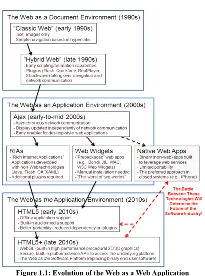
Figure 1.1: Evolution of the Web as a Web Application Platform (Taivalsaari &
Mikkonen 2011) ...17
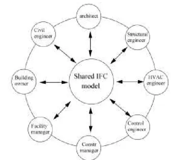
Figure 1.2: Information flow between different parties in AEC with a central database. (Chen et al. 2005)...18
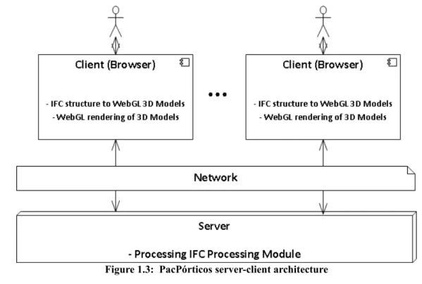
Figure 1.3: PacPórticos server-client architecture...20
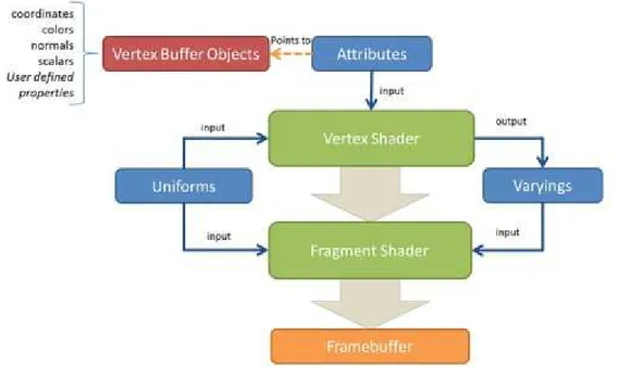
Figure 2.1: WebGL rendering pipeline overview(Cantor & Jones 2012)...25
Figure 2.2: HTML5 Related Technologies(Mavrody 2012)...27
Figure 2.3: X3D File encoding formats and programming language bindings(Behr & Michael 2009) ...31
Figure 2.4: IFC domain specific data schema map (BuildingSMART International Ltd 2011b) ...35
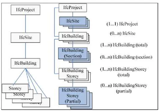
Figure 2.5: IFC spatial structure of a building project (Liu et al. 2010)...37
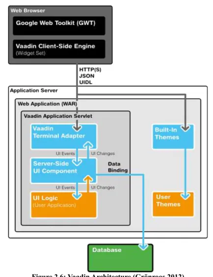
Figure 2.6: Vaadin Architecture (Grönroos 2012)...39
Figure 3.1: PacPorticos Architecture...44
Figure 3.2: Server-Client Workflow...46
Figure 3.3: Cube Mesh(Aaftab et al. 2009)...48
Figure 3.4: Spatial Transformations (Martins & Paciornik 2012)...49
Figure 3.5: Scene Graph...50
Figure 3.6: SuperDevMode...53
Figure 3.7: drawArrays primitive drawing call (Aaftab et al. 2009)...58
Figure 3.8: drawElements primitive drawing call (Aaftab et al. 2009)...58
Figure 3.9: Primitive Triangle Types (Aaftab et al. 2009)...59
Figure 3.10: IfcBoundingBox (BuildingSMART International Ltd 2006a)...60
Figure 3.11: IfcRectangleProfileDef (BuildingSMART International Ltd 2006g)...61
Figure 3.12: IfcExtrudedAreaSolid (BuildingSMART International Ltd 2006b)...61
Figure 3.13: Perspective projection viewing volume (Neider et al. 1994)...63
Figure 4.1: Login Form...66
Figure 4.2: User manager...67
Figure 4.3: Add user...67
Figure 4.6: IFC WebGL viewer...69
Figure 4.7: WallOnly.ifc IFC Engine Viewer...71
Figure 4.8: WallOnly.ifc prototype...71
Figure 4.9: x.ifc IFC Engine Viewer ...72
Figure 4.10: x.ifc prototype...72
Figure 4.11: 4walls.ifc IFC Engine Viewer...72
Figure 4.12: 4wall.ifc prototype...72
Figure 4.13: AC11-FZK-Haus-IFC.ifc IFC Engine Viewer...72
Figure 4.14: AC11-FZK-Haus-IFC.ifc prototype...72
Figure 4.15: WallOnly.ifc BIMSurfer...73
Figure 4.16: x.ifc BIMSurfer...73
Figure 4.17: AC11-FZK-Haus-IFC.ifc BIMSurfer...73
Figure 4.18: 4walls.ifc BIMSurfer...73
Figure 4.19: WallOnly.ifc IfcWebServer...73
Figure 4.20: x.ifc IfcWebServer...73
Figure 4.21: 4walls.ifc IfcWebServer...74
The web evolved and user interfaces changed at the same rate as new technologies emerged. It started with text documents with links to other documents, without animations or any interactive contents. After this initial period, the web finally gained interaction, animations and started to become popular. New plug-ins for the browsers appeared and made multimedia content possible within web pages (Taivalsaari & Mikkonen 2011).
In the earlier 90's, it was already possible to display 3D accelerated graphics in the web, however its usage was limited due to several reasons. The main reason was the low 3D processing capabilities for common users (Bochicchio et al. 2011).
In the 2000's, two trends in terms of web applications gained more visibility, the Rich Internet Applications (RIA's) and the Native Web Client Applications. The RIA's main idea is to use desktop programming technologies in web applications via plug-ins or custom runtimes. The Native Web Client Applications are binary installed software that are available though application distribution applications, made specifically for the mobile devices operating systems.
In the early 2010, a new HTML version was released, the HTML5. This last version offers a new array of technologies that enables the possibility of developing applications capable of matching the functionalities of RIA's and Native Web Client Applications (Taivalsaari & Mikkonen 2011).
HTML5 is referenced by some authors has the next step in web applications (Taivalsaari et al. 2011). Some others go even further and say that binary applications will perish, being replaced completely by web applications (Anderson & Wolff 2010).
It is not hard to predict that the future of education, visualisation, advertising, shopping, communication and entertainment will pass though Web3D no matter what technology will success the most (Vani & Mohan 2010). Web3D has the ability to process 3D accelerated graphics in the web, which was already mentioned previously, but now is made possible by the advances in hardware, bandwidth and optimisations in the browser's context. HTML5 features a technology that allows native 3D accelerated
graphics, through a technology called WebGL, which will be presented with detail further ahead.
Other technology that has evolved gradually in the last decade was the Computer-Aided Design (CAD) tools. Applications of the Architecture, Engineering and Construction (AEC) field have struggled in search of an interoperability format that makes a bridge between them. The Building Information Modelling (BIM) is the concept that makes that bridge, allowing to communicate, in digital format, information about geometry, spatial relations, geography, quantities, components properties and all other information concerning the modelling of buildings, other products and their life cycles (Suermann et al. 2009).
There has never been a widely accepted format of BIM by the AEC industry (Campbell 2007), until the release of the Industry Foundation Classes (IFC). IFC is an official standard candidate (ISO 2008) for BIM that is currently supported by almost all the main applications and tools on Architecture, Engineering, Construction and Operations (AECO) field (BuildingSMART 2011).
Figure 1.2 shows the different parties involved in AEC sharing information only using the IFC model.
Merging two technologies like WebGL and a rising standard like IFC may arguably be the next big step in the AECO software, as emphasizing interoperability and open standards may be the combination to success in the software industry nowadays (Campbell 2007).
1.1. PacPórticos Overview
This project was developed during a 10 month research at INESC Porto in the Manufacturing Systems Engineering Unit department, under the supervision of the scientific advisor Eng. César Toscano (INESC Porto 2012).
This research project is actually a sub project of a big AECO application being developed in parallel in other research projects. No further information can be said about the contents of the project because of the non-disclosure agreements with the companies involved.
In this dissertation it will be presented the merging of two technologies to solve a specific problem. The problem is the need to modernise a legacy application called PacPórticos made by the company Newton – Consultores de Engenharia Lda a few decades ago. PacPórticos is a software for structural analysis that provides automatic calculation of building structures behaviour, structural dimensioning of beams, columns and footings, static and dynamic analysis of horizontal actions and many others kinds of structural calculations (Newton Consultores de Engenharia Lda 2012).
and AEC tools. The focus is to reproduce a similar flow but in a more modern way, providing the user with a graphical interface to design and calculate structures, while giving emphasis to the portability issue. To achieve these objectives a web application was developed that uses IFC as an exchange file format and a WebGL engine that processes the IFC information allowing the visualisation of building structures directly in the browser. Figure 1.3 shows the server-client architecture of PacPórticos.
1.2. Objectives
The objectives are the conception and development of the two modules present in figure 1.3, the server and the client. The first objective is the development of a server module that will serve as a repository for IFC files. It will allow the user to upload files and keep them in a data base. The server will also do the first processing of the IFC files. The second objective is the client, that will enable the visualisation of IFC models in the browser. For a more detailed understanding of these objectives the consultation of figure 3.2 is recommended.
At this point, it can be identified the specific objectives in the scope of this project:
• Implementation of an IFC processing module;
In the IFC processing module the intention is to able to manage IFC files. This management module implies importing and exporting IFC files, and creating the data structure of the files in Java objects. The module will manipulate selected objects of the data structure and build a smaller structure to simplify the processing.
• Creation of IFC 3D models for WebGL visualisation;
To achieve this objective an in depth knowledge of the IFC structure and an analysis of the WebGL processing needs are required. The intention is to make the bridge between IFC and WebGL, providing a theoretical basis for the last objective.
• Development of a prototype that enables the representation of building
structures in the browser;
In this context, the conception and implementation of a working prototype will be presented. The prototype will have the ability to show IFC building structures in a WebGL based viewer.
The intent of this work is to show the process of achieving these objectives and show this new feature of the new PacPórticos software.
this process of Java calling C and C calling Fortran it was possible to call a Fortran routine from Java. These routines are made available in the web application via Java Web Services and will, in the future, be made public by the company for educational use. This part of the work will not be within the scope of this document because of intellectual property agreements.
1.3. Document Structure
This chapter presents different approaches of Web3D, clarifying their advantages and disadvantages. It contains an explanation about the structure and usage of BIM IFC, an overview about the Vaadin framework used in the development of the application and summary about the related work..
2.1 Web3D
Web3D is the ability to display 3D interactive content in web pages through a browser. Combining 3D graphics and web technologies needs more real-time rendering, more optimisation and more compression than previous 3D technologies, plus the investment in Web3D is still relatively small (Hongtao 2012).
Web3D is not a new concept however only know its usage is becoming more popular. This is because of the advances in hardware industry, browsers performance, user interaction, network, security, compatibility and interoperability that opened the possibility of a quality experience for the common user (Anttonen & Salminen 2011).
Web3D technologies are evaluated concerning five criteria:
• Simplicity (easy to install, use and deploy)
• Compatibility (platforms that are able to run the technology)
• Quality (performance, frame rate, maximum resolution and others)
• Interactivity (freedom and easiness to create interactive content)
The most relevant technologies which are capable of processing Web3D will be overview with some depth in the this section, giving special attention to WebGL, the chosen technology.
2.1.1 WebGL
WebGL was started by the Mozilla Foundation and the Khronos Group, this technology is an open, royalty-free, cross-platform standard for 3D accelerated graphics rendering in the Web without plug-ins (Ortiz Jr 2010), that complements other technologies in the HTML5 standard.
It is based in OpenGL ES 2.0 (Embedded Systems), the OpenGL version for mobile devices and operating systems. WebGL can be considered as the web-based version of OpenGL specification (Cantor & Jones 2012). In a more specific way, WebGL is a JavaScript binding for the OpenGL ES 2.0 API with full integration with Document Object Model interfaces, this means it can be combined with other web content. The API provides a web-based 3D environment for developing applications such as video games, scientific visualisations, and medical imaging (Khronos Group 2012).
client-side rendering the server sends the 3D scene to the client and the client takes care of the rendering. WebGL has client-based rendering, which in the majority of the applications is a lot more advantageous because if some work is being performed, for example building a 3D model, the work can be saved locally if there is no internet connection. It also eliminates bottlenecks like the network or server congestion (Cantor & Jones 2012).
To better understand the rendering process it is important to see all the steps that make it possible, these steps are called the rendering pipeline in figure 2.1. All the steps in the pipeline are programmable.
The Vertex Buffer Objects(VBO's) are the objects where the geometrical information is store, such as vertex coordinates, normals and texture coordinates. The Vertex Shader is the step where the information from the VBO's is computed, this information by attributes that point to the correspondent VBO. This computing is done for each vertex independently. The Fragment Shader is where the sets of vertex are fill to form a surface, this process is called rasterization. Rasterization can be in sets of one (points), two vertex (lines) or three vertex (triangles). The surfaces are called fragments and the
main idea behind the fragment shader is to define the color of each pixel that belongs to the fragment. Vertex and fragment shaders are written in OpenGL Shading Language (GLSL) that runs natively in hardware. FrameBuffer stores the surfaces or frames generated by the fragment shader. Once all the frames are processed a 2D image is generated to produce the final result to display on the screen. There are also varyings that are to pass data from the vertex to the fragment shader and the uniforms that normally contain lighting information to the vertex and fragment shaders. These are variable use in the shaders to optimise the performance or quality of the rendering (Aaftab et al. 2009).
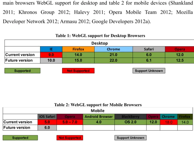
The recent versions of major web browsers already support WebGL natively, including Google Chrome, Mozilla Firefox, Safari and Opera (Congote & Sebastian 2011). Internet Explorer still hasn't announced is plans about WebGL support. Table 1 show the main browsers WebGL support for desktop and table 2 for mobile devices (Shankland 2011; Khronos Group 2012; Halevy 2011; Opera Mobile Team 2012; Mozilla Developer Network 2012; Armasu 2012; Google Developers 2012a).
Table 1: WebGL support for Desktop Browsers
Desktop
IE Firefox Chrome Safari Opera
Current version 9.0 14.0 21.0 6.0 12.0
Future version 10.0 15.0 22.0 6.1 12.5
Supported Not Supported Support Unknown
Table 2: WebGL support for Mobile Browsers
Mobile
iOS Safari Opera Android Browser BlackBerry Opera Chrome Firefox
Current version 5.0 5.0 – 7.0 4.0 OS 2.0 12.0 18.0 14.0
Future version 6.0
Chrome and Firefox Windows versions by default use Google's Almost Native Graphics Layer Engine (ANGLE) (Chromium Projects 2011) a library to translate WebGL GLSL shaders to Microsoft's HLSL language, compile and run them thought DirectX subsystem and other platforms. This operation improves compatibility with older systems. This change also can be disabled in browser configurations if the graphics card supports native OpenGL (Congote & Sebastian 2011).
WebGL runs in the HTML5 canvas element and data is generally exchanged via Document Object Model (DOM) interfaces, this allows the browsers to display 3D graphics natively without the use of plug-ins.
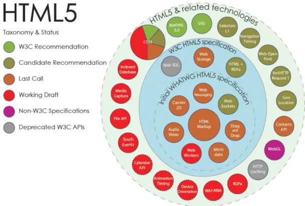
The HTML5 standard contains a good amount of new features that makes web applications to look more alike desktop applications. Figure 2.2 shows the technologies that enables HTML5 to perform more like desktop applications.
There are several frameworks and libraries for WebGL (Taivalsaari et al. 2011). These are the development libraries worth of mentioning:
• C3DL (http://www.c3dl.org/)
• Copperlicht (http://www.ambiera.com/copperlicht/)
• CubicVR (http://www.cubicvr.org/)
• EnergizeGL (http://energize.cc/)
• GLGE (http://www.glge.org/)
• Jax (http://blog.jaxgl.com/)
• O3D (http://code.google.com/p/o3d/)
• Processing.js (http://processingjs.org/)
• SceneJS (http://scenejs.org/)
• SpiderGL (http://spidergl.org/)
• StormEngineC (http://code.google.com/p/stormenginec/)
• Three.js (https://github.com/mrdoob/three.js)
• WebGLU (http://github.com/OneGeek/WebGLU)
wrappers show that the development in WebGL is becoming very popular and new applications are being released everyday.
Satisfying rendering rates can be achieved in WebGL without any specially customised hardware, as well as good frame rates for data visualisation. Eliminates the need for dedicated language, no plug-in required for interpretation, portable across browsers, devices and operating systems and advanced rendering support. Unlike other Web3D standards WebGL's imperative graphic programming enables great flexibility and exploits the advanced features of modern graphics hardware (Congote & Sebastian 2011). All these features and many others that are still under definition, make the WebGL a very powerful and exciting standard, that eventually will change the way that browsers interact with end users and consequently change the way that future web applications will be (Taivalsaari & Mikkonen 2011).
2.1.2 X3D
X3D or ISO/IEC 19775 is a standard for network-enabled 3D graphics and multimedia. By defining interactive web and broadcast-based 3D content integrated with multimedia X3D is intended to be used in a variety of hardware devices and application ranges such as engineering and scientific visualisation, multimedia presentations, entertainment and educational titles, web pages, and shared virtual worlds. It is the successor of the original standard for web based 3D the VRML (ISO/IEC 14772), X3D add new features to the original standard which only defined 3D interactive vector graphics. The more noticeable features are (ISO/IEC 2012):
• 3D graphics – Polygonal geometry, parametric geometry, hierarchical
transformations, lighting, materials and multi-pass/multi-stage texture mapping
• 2D graphics – Text, 2D vector and planar shapes displayed within the 3D
• Animation – Timers and interpolators to drive continuous animations;
humanoid animation and morphing
• Spatialized audio and video – Audiovisual sources mapped onto
geometry in the scene
• User interaction – Mouse-based picking and dragging; keyboard input
• Navigation – Cameras; user movement within the 3D scene; collision,
proximity and visibility detection
• User-defined objects – Ability to extend built-in browser functionality
by creating user-defined data types
• Scripting – Ability to dynamically change the scene via programming
and scripting languages
• Networking – Ability to compose a single X3D scene out of assets
located on a network; hyperlinking of objects to other scenes or assets located on the World Wide Web
• Physical simulation – Humanoid animation; geospatial datasets;
integration with Distributed Interactive Simulation (DIS) protocols
• Geospatial positioning – Ability to accurately position X3D scene objects
geospatially.
• CAD geometry – ability to represent CAD models mapped from CAD
• Layering – Ability to organise X3D scenes into rendering groups so that
objects in each layer can overlay objects in underlying layers.
• Support for programmable shaders – Ability to replace the X3D lighting
model with custom shader programs.
• Particle systems – Ability to generate systems of particles that can
represent fire, smoke, and other such effects
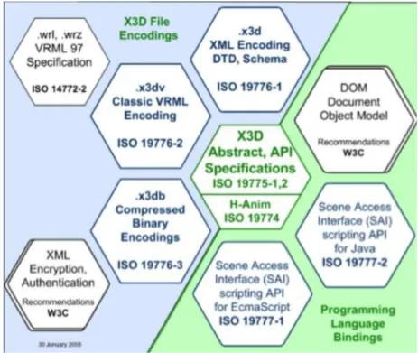
Connection to external modules and definition of functional requirements via profiles (set of components) is also one within the X3D specification, among those profiles are included the X3D Core, X3D Interchange, X3D Interactive, X3D CADInterchange, X3D Immersive, and X3D Full. It also possesses a various number of formats and programming language bindings as it can be acknowledged in figure 2.3.
Anslow points in is masters thesis (Anslow 2008) the major advantages of X3D, that are rich graphics, extensibility and XML integration. However Anslow also points that being a plug-in technology it inherits the common drawbacks of OS and browser incompatibility, security and installation issues, plus it has is own problems of lack of visualisation softwares, primitive animation model, weak support for filtering and layout.
For some of the reasons stated above some specialists like 3DVIA's Laubner stated (Ortiz Jr 2010) that X3D never caught on in the 3D developing community and was largely ignored.
2.1.3 Adobe Flash
Adobe Flash is a platform that adds animation, multimedia and interactive contents to web pages. Although being considered now by Adobe as a platform for RIA's (Adobe Systems 2012b) it has been since the Macromedia times a 3D technology for web. Using Flash Player on desktops or Flash Player Lite on mobile devices, that are ActiveX based plug-ins, it is able since the version 10 (Ortiz Jr 2010) to do 3D accelerated graphics rendering, manipulating vector and raster graphics to provide animation to text, drawing and still images in web and standalone applications (Adobe Systems 2012a).
It has his own object oriented programming language called the ActionScript, derived from the ECMAScript and consequently from JavaScript. ActionScript is based in a set of commands called by Adobe System “actions” that could contain variables, expressions, if statements, operators and loops (Gawecki 2011).
2.1.4 J3D
Java3D is a cross-platform 3D API for the Java platform and it is based on a scene graph structure. To be able to process accelerated 3D graphics J3D runs on top of renderers like Direct3D or OpenGL. J3D runs on web via applets, which usually call the Java Virtual Machine to run a JAR file. Included in HTML the same way as an image but using the <applet> tag (now replaced by <object>), the Java Runtime Environment it is called by the browser and the compile code is executed (Vani & Mohan 2010).
It was surrounded by a big hype in his earlier days because if it has many advantages like being cross-platform, mostly client based reducing the overhead, good performance compared to native software and the browser caching made it easy to load. After sometime of usage it started to show his flaws namely his plug-in requirement, mobile browsers do not support applets, bad accessibility and the biggest problem is that an applet depends on the version of the JRE creating severe backward compatibility issues (Roberts 2007).
2.1.5 Unity
Unity is a cross-platform development tool mainly used for 3D games development (Unity Technologies 2012a) but it can also be used in architecture visualisations (Buchhofer 2011). Supports JavaScript, C++ and a dialect of Python called Boo, with all the three it is able to make database connections, networking, media integration (namely with Flash) and all the other features that mainstream languages can do.
For the web, Unity has two major problems: the first one is the need for a custom unity player plug-in that only runs on some browser builds for Windows and Mac; the second problem is that additional amount licensing is need to develop for mobile devices. For instance, if we want to develop to Android platform we have to buy a Unity Pro and an Android Pro licence (Unity Technologies 2012b).
2.1.6 Microsoft Silverlight
Microsoft's Silverlight is an API for RIA, and version 5 is capable of processing accelerated 3D graphics in the web. Using the XNA libraries Silverlight can do data visualisers, 3D charts, scatter points, geographic overlays, and 3D games and simulations. It is called by using the HTML <object> tag and the browser Silverlight plug-in calls the OS rendering engine (Microsoft 2012b).
As it is a Microsoft technology it lacks a lot in compatibility specially for mobile devices, working only on windows type devices, and for desktop works good in Windows OS's but, in other OS's it only works in a few builds of some browser (Microsoft 2012a)
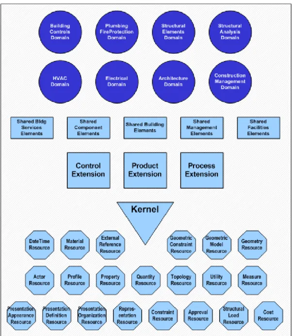
2.2 BIM IFC
On the verge of becoming the standard for BIM (ISO 2008), IFC is an open specification that allows exchange information between all parties in a building conception. It covers a total of 8 domains of the AECO industry as it shows in the figure 2.4.
The specification of the IFC standard can be represented as two data schemas both are parts of the STEP or ISO 10303 standard:
•Based in XPRESS or ISO 10303-11. The implementation method called
STEP-File 10303-21 an easy to read data exchange of product model, due to his ASCII structure usually with an instance per line (ISO 2002; ISO 2004).
•Based in XML called STEP-XML or ISO 10303-28. An implementation
method that uses XML to represent the XPRESS schema (ISO 2007).
In order to develop an application that supports IFC, it is required to support a well defined subset of the data schema, these subsets are called model view definitions. Every model view definition has is defined subset schema to store all the data of one or many work flows from the building construction and facility management industry sector (BuildingSMART International Ltd 2011b).
In this work we will focus on the structural elements domain and the shared building elements. This will allow us to have not only information structural elements but also information about all the building elements.
IFC has a hierarchical structure and all the entities in the IFC schema have the prefix “Ifc”. By definition the root entity of a building project is the IfcProject., this Project is a container for all the other entities and defines information important to all the other elements, for example the default international system units and prefixes applied to those units (BuildingSMART International Ltd 2006f). The other levels are IfcSite, IfcBuilding and IfcBuildingStorey.
that represent the multiple building elements present in a storey, such as IfcWall, IfcColumn, IfcBeam and many others.
All these entities inherit the proprieties of IfcProduct, except IfcProject, that helps to define spatial or geometric context. The properties are IfcObjectPlacement and IfcProductRepresentation, object placement defines where is the object in the geometrical space and the representation which shape will the object (BuildingSMART International Ltd 2006d).
IfcObjectPlacement not only represents positions but also represents orientation. There are three types of object placement the absolute, relative and grid. The absolute uses always the World Coordinate System present in IfcProject as reference. The relative uses the object placement another product as reference normally the previous in hierarchy, for example a building element will use the building storey reference and the building storey the building. The grid placement virtual use the intersection and reference direction given by two axes of a design grid (BuildingSMART International Ltd 2006c).
The IfcProductRepresentation (BuildingSMART International Ltd 2006e) is the topological or geometrical representation of the object. A product or object can have zero, one or several geometric representations and the same representation can be shared by many objects. It can be a plane, circle, sphere, cube, solid and many other representations.
This vast hierarchical structure of IFC makes possible to AEC applications to map their own models into the IFC correspondent, in order to ensure interoperability between them. However some interoperability benchmarks (Jeong et al. 2009) still show some mistakes in terms of 3D information in the development of applications.
2.3 Vaadin Framework
Vaadin is a Java framework for web based applications development. This framework comes as a Java library that saves a lot of time to programmers handling software engineering problems during the development process. The mains advantages of using this framework are that all the code is written in pure Java and server-client communications are simplified.
The server side runs as a Java Servlet session in a Java application server and the client-side runs as a HTML and JavaScript on the web browser. A Vaadin application runs on the server has a servlet, serving HTTP requests. This requests are handled by the terminal adapter. The client events are interpreted by the Java Servlet API for each user session. After the events being processed in the Server-Side User Interface Component a response is generated to be sent to the client-side counterpart. Normally it would be need also to develop the client-side in HTML and JavaScript but Vaadin makes use of the Google Web Toolkit (GWT) to do that work. GWT applications are also written in Java and compiled into JavaScript by the GWT compiler, this compiler supports a large range of web browser, so the developer doesn't need to do different builds for different browsers. However GWT applications still need to communicate with the server. Communication is achieved using Asynchronous JavaScript and XML (AJAX), to make
a better client interactive experience, more responsive applications, almost like communications between client and server in desktop applications. The communication between browser and server requires the use data object serialisation, in order to transmit data objects through network connection. The new builds of Vaadin use GWT JSON interface instead of the traditional XML, this makes the application object serialisation much faster (Nurseitov et al. 2009). GWT allows the creation of very advanced user interface components called Widgets (Google Developers 2012b). These Widgets give freedom to programmers to create interaction and logic in the browser, even more with the insertion of HTML5 related technologies already presented in figure 2.2.
Vaadin makes a clear distinction between user interface and logic, allowing both to be developed separately. The themes in Vaadin are what dictate the user interface appearance, these themes use Cascading Style Sheets(CSS) or optionally HTML page templates (Grönroos 2012)
There several reasons behind the election of the Vaadin framework for this work, all of them promoting a faster deployment of applications. The large amount of interface components, controls and Widgets is very useful when developing a good user interface. The default themes and style are very clean, good looking and easy to alter. Vaadin's GWT basis that allow the developer to program only in Java language, not wasting time programming in HTML and JavaScript.
2.4 Related Work
The following three projects, that merge IFC models and WebGL, were identified: BIMSurfer, BIMShare and IFCWebViewer.
experience while navigating the models, very smooth, with a lot of interactive features like Storey sliding and object picking. It uses the BuildingSMART library to parse the files and transforms them into a JSON scene graph. A similar approach to the one used on the prototype produced in this document, with the main difference being the usage of a scene graph JSON API called SceneJS, that aids in the manipulation of the scene graph (Lindeque 2011).
BIMShare is JavaScript API owned by Gehry Technologies, that allows the upload and visualisation in WebGL of IFC models. The viewer is BIMSurfer with some minor modifications. BIMShare state on their website that they are using third party software from BIMServer (Gehry Technologies 2012).
IFCWebViewer is the viewer of the IFCWebServer open-source project. The IFCWebViewer enables the viewing of IFC models in the browser with WebGL support. It uses the Javascript library SpiderGL to aid in the rendering process. Supports all version of IFC by default, however with large structures the frame rate drops significantly (Ismail 2012).
2.5 Summary
3.
Method
In this chapter is presented, step by step, the conception and development of the PacPórticos application. Both conception and the development sections are subdivided into the server and the client-side, to make the understanding more clear and to allow the distinction between the two different sides of the overall application.
3.1 Conception
The PacPórticos application, as already mentioned, has three main modules but only the item one and two will be described:
1. The server-side where it will be managed the users and IFC files;
2. The client-side, running inside the browser, where the 3D building models will be displayed;
3. The WebServices module where the fortran calculus routines will be called;
In order to validate the prototype, the following requirements needed to be met:
Functional requirements:
1. Simple authentication system;
2. User manager to add, edit and delete users;
3. IFC file manager per user, each user can add and delete his own files;
5. Viewing IFC models correctly;
6. The viewer must allow basic navigation controls: pan, zoom, rotation;
Non-Functional requirements:
1. Multiple viewers can be opened at the same time;
3.1.1 Server-Side Module
This section explains the concepts and thought process behind the conception of the Server-Side Module. Starting with the way that Vaadin application handles the IFC files and process them, culminating in the creation of a model that will be sent to the client-side module.
3.1.1.1 IFC Processing and Model Creation
The server-side module also contains a simple authentication system and database management system that, although not very pertinent for this work, will be mentioned briefly in the development section.
The most important part of this module is the IfcFileProcessing system, that reads an IFC file in both standard formats, STEP or XML, parses and transforms it into Java objects with Eclipse Modelling Framework (EMF) (The Eclipse Foundation 2012a). EMF is a modelling framework based on a structured data model, for example an XML Schema, and can generate an EMF ECore file. Using this file the framework can generate a set of annotated Java Classes that correspond to the same structured data model. This framework is useful to generate Java Classes from big structured data models like IFC. Without this framework it would be a serious time commitment to implement all the IFC model in Java.
The process of transforming a stream of bytes into an object is called deserialization or unmarshalling. The inverse process of transforming an object into a stream of byte is called serialisation or marshalling.
The parsers used in the IfcFileProcessing module are from a project called BIMServer (BIMServer 2008). BIMServer project is an open source centralised data base for the IFC standard. Allows user from across all the sector of the AECO industry to work together by providing an interface to interact with BIM IFC projects, query them on the fly, merging parts of the project and many other useful operations.
SharedState (Vaadin 2012c). The way overcome this problem is to extract the objects needed from the IfcModelInterface and create a new model that contains the information needed without circular references, that was called IfcDataModel. This measure will also optimise the amount of data that is transmitted to the client.
After creating the new data model it is defined an object that contains all the data from data model, called simply Project. This object will serve as a carrier for all the data that the client will use. This data model is needed because Vaadin demands that the source code of the objects used in the client side must be present in the client-side package.
Figure 3.2 shows the workflow described for the Server-Side and it is usage in the Client-Side.
3.1.2 Client-Side Module
The client-side is a Vaadin widgetset, a set of Widgets working together. This section explain the conception of the IFC WebGL 3D engine based on a Scene Graph approach.
3.1.2.1 IFC WebGL Widget
The client-side module is based in the GWT G3D (Nguyen 2010). This 3D library for GWT, is a Java implementation of the main WebGL functions. These functions when compiled, using the GWT compiler, are transformed into WebGL JavaScript functions and will run inside a HTML5 canvas. GWT G3D provides a Widget called Surface3D, this Widget is a HTML5 canvas with WebGL context. This will allow the creation of a 3D engine for IFC models.
The name of the Widget that will process the IFC information and transforms it into WebGL commands is called IfcWebGLWidget. This Widget will extend the Surface3D Widget so it inherits his properties and enables the usage of WebGL functionalities. The next is creating an engine capable of transforming the geometric data of the Project object into WebGL information.
3.1.2.2 Scene Graph
To create a 3D engine capable of processing the Project data model it was used a Scene Graph approach. A Scene Graph is a data structure that allows the representation of a hierarchical 3D scene. It is very useful in computer graphics because it creates an abstraction of the 3D rendering system. More specifically a Scene Graph is a direct acyclic graph, i.e., a graph that does not contain cycles (Bouvier 2002).
meshes of triangles, each triangle is a group of three 3D points (vertex). To improve performance the same vertex in several triangles can be used in order to construct the mesh. Figure 3.3 shows a cube mesh using the same vertex in different triangles.
Branch Groups represent every abstract object like a column or a building, a Branch Group can have multiple Leaf Nodes, for example a wall can be represented by multiple cubes.
Transform Group represent spatial transformations operations that will affect all the children nodes and consequently all the nodes that are in the same branch. Transform Groups have a transformation matrix at is used to perform three different types of spatial transformation operations. Scaling that increases or decreases the size of the mesh, rotation that makes the mesh rotate around a specific point in space and translation that positions the mesh in a specific point in space. These transformations allow branches of the hierarchy to be positioned, rotated and scaled if needed. Figure 3.4 shows a base image transformed using the three spatial transformations mentioned.
The root node is a Branch Group represents the Project object, that in the server-side model and in the IFC model are the containers to all the other objects.
The child of the root node is always a Transformation Group that contains the International System Prefix the will be used to scale all the model into the correct size. For example if the prefix is “milli” all the coordinates have to be multiplied by 10-3.
This Transformation Group can have now many Branch Groups as his children, it depends on how many construction Sites the project have, replicating the IFC hierarchical structure explained previously. The Sites Branch Groups can have several Branch Groups that represent the Buildings, Buildings Branch Groups can have several Branch Groups that represent Building Storeys.
If the Project uses absolute placement, as already explained in the BIM IFC section, each BuildingStorey Branch Group only has one child Transformation Group that represents the World Coordinate System. If the Project uses relative placement each BuildingStorey Branch Group as a hierarchy of five Transformation Groups each one representing the placement of abstract objects of IFC, starting with the World Coordinate System for the project and the relative placements for the Site, Building, Building Storey and Building Element.
After the Transformation Group that represents the Building Element there is the Branch Group that represents the Building Element. After this Branch Group there are are many Transformation Groups as there are primitive objects needed to represented the Building Element of the Branch Group. The Scene Graph ends with the one leaf node for each of the Transformation Groups representing each primitive object.
All these concepts are important to understand the phase of development where it will be presented the more technical issues of the project.
3.2 Development
This section describes in detail the implementation of the prototype application. Starts by identifying the development environment and frameworks used, explains the implementation of the server-side module and finishes with a very detailed description of the client-side module development.
3.2.1 Development Environment and Frameworks
The development environment used was Eclipse Indigo IDE, a known open source development platform initially developed for Java language programming. Eclipse has a large amount of useful plug-ins that extends the IDE capabilities like compiler and editors for different programming languages, server development platforms, modelling tools and many others.
In terms of Java, it was used the Java Development Kit version 1.6.0. This decision is based on dependencies of the Vaadin 7 alpha 3 Framework, that only supports Java 6. Using the Vaadin plug-in for Eclipse it is possible to create and maintain Vaadin projects and Widgets. Vaadin 7 alpha 3 has Google Web Toolkit 2.5.0 built in and by using the plug-in for Eclipse it is possible to compile the client-side into JavaScript by pressing the compile Vaadin Widgets button (Vaadin 2012a).
The database chosen was the HyperSQL 2.2.9 an open source relational database engine fully written in Java Language. This database has the option to run embedded in the application. The advantage of using this embedded mode is that no external installation of the database management system is needed when deploying.
The code is considerably big so for testing proposes it was used JUnit Framework version 4.10. This framework allows the creation of test instances to test the output of each method present in any class. Only the core methods are tested, to make sure that newer versions of the application do not influence the behaviour of previous versions code.
As it was already mentioned in the Conception it is used a wrapper of WebGL in GWT called GWT-G3D in the version 0.07. This might be a very early version but the intent is just to use the Canvas with WebGL context, so no advanced versions are needed. The library also contains a lot of utility implementations, like a very useful custom implementation of matrix stack, to compensate the lack of native matrix stack support in WebGL.
3.2.2 Server-Side Module
When the application starts the user is directed to a classic login form. This form is the class LoginWindow, it connects with the database by a LoginManagerService class to perform the proper authentication. The LoginManagerService retrieves the password of username entered by the user. Uses a EncryptionService class to encrypt the password given by the user and compares it with the retrieved one.
After the authentication is succeeded the user enters a part of the application where there are 3 possibilities available. The Main window, the About window and the Logout Window. These classes have the names MainWindow, AboutWindow and LogoutWindow respectively. The Logout Window just makes the session logout and returns the user to the LoginWindow. The About Window have some labels with information about the application. The Main Window has several different tabs inside it.
First tab for Users, if the user has the proper permissions to have this tab enabled. Second tab is called IFC Files where the user can manage the IFC files that he uploaded, in this tab it is possible to open IFC files. When the user opens a IFC file the application open a new tab with the name of the file and display a IfcWebGL Window. This IfcWebGL Window is what runs the IfcWebGLWidget, that is the client-side application.
In order to work with the IFC files in the client-side first we need to do a unmarshalling operation, already explained in the Conception chapter. The class responsible for that is called IfcUnmarshaller. This is a singleton class that creates a InputStream from the file retrieved from the data base and processes it. The method of this class that processes the InputStreams is called unmarshallFromInputStream and returns a IfcModelInterface. The method checks the extension of the file. If the file has the extension “.ifcxml” it is used the IfcXmlDeserializer a class present in the BIMServer library, that reads a ifcxml InputStream and transforms it into Java Classes. If the file has the extension “.ifc” it is used the IfcStepDeserializer also present in the BIMServer library, that does the same process that the IfcXmlDeserializer but for step format files.
The mechanism used to allow the server to communicate with the client is the SharedState. This mechanism just uses two classes to control the state of objects passed by the server to the client. The classes are IfcWebglConnector and the IfcWebglState. The IfcWebglState contains the objects needed in the client-side, like the Project object for example. The IfcWebglConnector controls the IfcWebglState objects state and triggers events in the client whenever their state changes. The complete class diagram of the Server-Side Modulo is available on Annex A figure 2.
Now that the Project object is on the client side, the Server-Side Module is over and the application continues in the Client-Side Module. Like shows in bottom right of figure 3.2 when in the Project pass from Server-Side to the Client-Side.
3.2.3 Client-Side Module
The Client-Side Module starts in IfcWebglConnector, that has a method to create a Widget, in this case the IfcWebglWidget. When the IfcWebglWidget is created the Project object is set into it. The IfcWebglWidget has two different moments: the initialisation and the rendering.
The initialisation is a pre-processing operation that initialises all the needed objects needed to process the scene. The initialisation contains the following 5 steps:
1. WebGL context creation;
2. Shader definition;
3. Construction of the Scene Graph;
4. Mouse Handler creation;
For better understanding the rendering moment will be explained within the Scene Graph construction
3.2.3.1 WebGL Context and Shader definition
The WebGL context and the Shader used are from the GWT-G3D library. The context defines the background color, the viewport, color depth and other basic definitions related with the WebGL canvas.
As this is a prototype application, there is no texturing and the Shader used is a Flat Shader. A Flat Shader reflects the light uniformly in all directions, using only one color for each mesh. This shader is also part of the implementation of the GWT-G3D library.
3.2.3.2 Scene Graph Implementation and Rendering
The construction of the Scene Graph is a recursive process that begins in the root of the graph and goes down to the leafs. This is done by making the Branch Groups create their Transform Groups and sons, their sons create their Transform Groups and grandsons until it reaches the leafs. The Project, for example, create a Transform Group for the SI prefix and a set of Branch Group sons for all the Sites. Each Site creates a Transform Group for the placement of the Site and a set of Branch Groups for each Building. This process goes on until it reaches the primitive object like a BoxNode, that will not possess sons.
bottomVertices = new float[] { 0, 0, 1, 0, 0, 0, 1, 0, 1, 1, 0,
0 };
topVertices = new float[] { 0, 1, 1, 0, 1, 0, 1, 1, 1, 1, 1,
0 };
middleVertices = new float[] { 0, 0, 1, 0, 1, 1, 1, 0, 1, 1, 1,
1, 1, 0, 0, 1, 1, 0, 0, 0, 0, 0, 1, 0 };
As the names of the arrays indicate they correspond to the vertices each of the faces. Top face, bottom face and the four middle faces. This vertices will be used to create vertex buffers and will be bound to a data buffer. The data buffers are what is passed to the WebGL primitive drawing calls to render the Scene when the Graph is completely constructed.
Whenever a vertex buffer is bound to data buffer the developer has to specify the vexterAttribPointer. This method indicates to WebGL the number of components per attribute, the type of data of the components, if the components need normalisation, the byte offset between consecutive generic vertex attributes and the pointer to the first component. This data is important mainly to define the number coordinates per vertex, in this case three.
WebGL uses types of primitives that are geometric objects to render. The geometric objects supported are points, lines and triangles, being the most common in the 3D applications the triangles. There are three distinct type of primitive triangles. The first one is draw separated triangles, this means that it is not possible to reuse the same vertex in different triangles. The second one is to draw triangles in a strip, drawing a
Figure 3.7: drawArrays primitive drawing call (Aaftab et al. 2009)
series of connected triangles. The third one is to draw triangles in a fan, using always the same first vertex is used in all the triangles. Figure 3.9 show the three primitive types for the triangles.
In some cases IFC demands geometric representations to be more complex than simple cubes, spheres or cylinders. These complex geometric representations are called shape representations. Each IfcBuildingElement contains at least one shape representation. There are ten types of shape representations, some of them are specific to certain building elements and others are generic. In this prototype it is only implemented two generic shape representations, the BoundingBox and the SweptSolid.
The IfcBoundingBox is very trivial to implement, it has four attributes. The x, y and z dimensions and the corner. The dimensions are the measures of the box in each direction and the corner is the location of bottom left corner of the box, being always the point with the smaller x, y and z of the box. Figure 3.10 shows the IfcBoundingBox geometric definition. This shape is implemented with a BoxNode and a Transformation group with two spatial operations. First is performed a scaling operation in all the three axis corresponding to the three dimensions of the BoundingBox. The last operation is the translation that positions the corner of the box in the specified position.
The other generic shape representation implemented was the IfcSweptSolid. This shape representation restricts the representation of a solid model to only include swept solids. This swept solid normally uses an IfcExtrudedAreaSolid an object that contains a placement, a depth, extruded direction and a primitive profile or a polyline. The primitive profiles like the rectangle profile, that is a rectangle with x and y dimension, placed in a point in space. Then extruded direction is a vector that controls the direction in which the solid depth will go (Liebich 2009). Figure 3.11 shows the
IfcRectangleProfileDef and figure 3.12 the IfcExtrudedAreaSolid geometric definition representation.
Figure 3.11: IfcRectangleProfileDef (BuildingSMART International Ltd 2006g)
This can be easily done by using a BoxNode and a Transform Group with the proper spatial operations. First using scaling operation in the three axis, being x the x dimension and y the y dimension of the rectangle profile and z the depth of the extruded area solid. Then rotation operation, rotating the solid to match the extruded area direction vector. Finally the translation operation, positioning the solid in the extruded area solid position. As this spatial operations are matrix multiplications the sequence of operations is pivotal, changing this sequence of operations will results in undesired solids. In this way we can represent solids with common profiles like the circle, ellipse or the trapezium and more uncommon ones like the U, T, L and the C profiles, that are used to represent types of beams and columns.
A Polyline is a set of bi-dimensional points that connected together form a polygon. As there are no primitive leaf node that can predicted the shape of these polygons, the points are insert in a triangulation class to be transformed into a triangulated solid. The triangulation algorithm used was an adaptation of an algorithm that triangulates a polygon via ear clipping and compute area, present on the book Programming Challenges (Skiena & Revilla 2003). After the algorithm triangulates the polygon, that corresponds to the bottom face of the solid, this sequence of triangulated points is replicated to the top face just by changing the z axis value one instead of zero. The missing triangles are from the middle faces, that can be calculated based on the bottom and top faces.
When the Scene Graph is completely built the it is need to have a way that give possibility to navigate and see the drawn elements.
3.2.3.3 Mouse Handler and Camera
definition of the area seen by the camera, this definition is done according to six parameters:
1. The eye, the point in space where the camera is located;
2. The target, a vector that represents the direction in which the camera is pointing;
3. The field of view, the angle in radians that the camera covers;
4. The aspect, the ratio between width and height of the image;
5. The near plane, distance between the camera and the front plane of the perspective;
6. The far plane, distance between the camera and the back plane of the perspective;
Figure 3.13 shows the perspective projection viewing volume of a camera.
To navigate in a scene with this camera only the mouse is used, this means it was not taken into account the mobile device in this version of prototype. The mouse handler contains information about the mouse behaviour within the WebGL canvas. This mouse handler and the camera are connected, the mouse handler listens to mouse events and map them into camera movements. There are three types of camera movements, which are the pan, the rotation and the zoom.
The pan movement is done when the mouse handler detects that the middle mouse button was pressed and the pointer moved within the canvas area in the screen. This measures are calculated in the x and y planes and the amount of pan is obtained by the resulting radian angle of the difference between the new and the last mouse positions. This event when it is mapped into the camera, will change target parameter so the camera turns left and right for horizontal, up and down for vertical movements of the mouse.
The zoom movement is detected in the mouse wheel or mouse scroll. The zoom level increases each time the mouse is scrolled down and decrease when scrolled up. The camera moves the eye position closer and farer in the direction of the target. This means increasing and decreasing the z coordinate of the eye position. If the camera reaches the target point by zooming in, the camera will start to move away from the target again if the user keeps zooming in.
The rotation movement is detected by pressing the left mouse button and moving the pointer within the canvas area. It the calculation is done in the same way as the pan movement, but instead of changing the camera target it changes the camera eye position. This means the eye will orbit around the target in all directions. Every time that these events are triggered the camera is instantly updated in the canvas and the user moves around the scene freely.
3.3 Summary
4.
Analysis and Results
Along this chapter will be presented the obtained results, namely, it will be described some tests done with the developed application as well as the application itself, with respect to its graphical interface. A final analysis of the achieved objectives , taking into account the project requirements, is also presented in conjunction with a discussion and identification of some limitations.
4.1 Results
In this section will be show the graphical user interface of the application and explained the tests performed to the application.
4.1.1 User Interface
The system start with the login form, displayed in figure 4.1.
After the authentication the user is directed to a menu with the label “Main” that has two sub-menus. The first one with the name contains a table to manage users (figure 4.2). This manager allows insertion (figure4.3), deletion and edition of users.
Figure 4.2: User manager
In the second menu there is the IFC file manager. Each user can manage his files independently (figure 4.4) performing the add (figure 4.5), remove or open operations.
Figure 4.4: IFC file manager
After adding an IFC file it is possible to open the file in the WebGL viewer (figure 4.6)
In the viewer the user has buttons that allows the changing of perspective, activate and deactivate all the building elements, activate and deactivate the Cartesian axis and a grid in the xy plane.
To navigate inside the canvas is possible to use the mouse to perform the following operations:
• Zoom – zoom in and out in the model (mouse scroll);
• Pan – move horizontally and vertically in a plane in space (pressing the middle
mouse button and moving the mouse);
• Rotation – rotate in all direction, orbiting around an approximated point in the
middle of the model;
4.1.2 Performed Tests
Software engineering tests using JUnit
The prototype has been submitted to several test units made with the JUnit 4.10 framework (Kent et al. 2012). These test units are assertion tests, to make sure the different modules of the application are correctly created and working within normal parameters. This test units are normally used in the development of application to check if the changes in certain parts of the code did not influence other modules. The profiling units were left to future developments of the application. These were the test units done for that purpose:
1. IfcUnmarshallerTest – Tests the deserialisation of several IFC files into Java objects, resulting in a Project object;
2. IfcMarshallerTest – Tests the serialisation of several Java objects into IFC files, this is done performing the IfcUnmarshallerTest and using the objects to do the inverse operation;
3. IfcDataModelBuilderTest – Tests the correct build of the server-side data model creation;
4. ProjectSceneGraphTest – Test if the scene graph is correctly built for several Project objects, previously unmarshalled and built by the test 1 and 3;