Luiz Claudio Pardini*
Institute of Aeronautics and Space São José dos Campos – Brazil [email protected]
Maria Luisa Gregori
Institute of Aeronautics and Space São José dos Campos – Brazil [email protected]
*author for correspondence
Modeling elastic and thermal
properties of 2.5D carbon iber
and carbon/SiC hybrid matrix
composites by homogenization
method
Abstract: Advanced carbon iber hybrid carbon-ceramic matrix composites
are realizing their potential in many thermostructural components for aerospace vehicles. This work presents ab-initio predictions of elastic constants and thermal properties for 2.5D carbon iber reinforced carbon-silicon carbide hybrid matrix composites, by using the homogenization technique. The homogenization technique takes properties of individual components of the composites (iber and matrix) and characteristics of the geometrical architecture of the preform to perform calculations. Ab-initio modeling of mechanical and thermal properties is very attractive, especially during the material development stage, when larger samples may be prohibitively expensive or impossible to fabricate. Modeling is also useful when bigger samples would be prohibitively expensive or impractical. Thermostructural composites made of 2.5D preforms are easy to manufacture in relation to 3D preforms. Besides, 2.5D preforms are also resistant to thermo cycling and have high resistance to crack propagation in relation to ply stacked composites such as unidirectional (1D) and bidirectional (2D) structures. The calculations were performed by setting an overall carbon iber volume fraction at 40, 45 and 50 for a 2D stacked composite, and volume fraction in Z-direction of 2, 4 and 6.
Keywords: Mechanical properties, Carbon-SiC composites, Elastic
properties, Thermal properties.
INTRODUCTION
Advanced iber-reinforced composite materials have been widely used in various load bearing structures, from sporting goods to aerospace vehicles. The ever-increasing popularity of iber-reinforced composites is largely due to their lightweight, high strength, and superior structural durability. The microstructure of composites plays a dominant role in forming all the composite properties, including failure mechanisms. In principle, property characterization of ibrous composites should be based on their precise microstructures. In practice, however, the true microstructures of the composites are often simpliied in the characterization models, both geometrically and from the point of view of materials. The degree of simpliication depends on the desired engineering accuracy. The theory of homogenization (Yan, 2003) is almost universally applied to characterize ibrous composite properties. Composite homogenization is a mechanics-based modeling scheme that transforms a body of a heterogeneous material into a constitutively equivalent body of a homogeneous continuum. A set of effective properties is obtained for the equivalent homogeneous continuum. Homogenization
is an essential irst step towards the design and analysis of larger scale and load-bearing structures in ibrous composites. The analysis of a multidirectional composite made of a single unidirectional iber-reinforced lamina is a classical example. In this case, the unidirectional single lamina is irst homogenized, each one with a set of effective properties. The laminate is then treated as a layered plate structure, capable of carrying globally applied thermomechanical loads.
Composites can be divided according to their temperature use. At high temperatures (T>500°C), only composites made
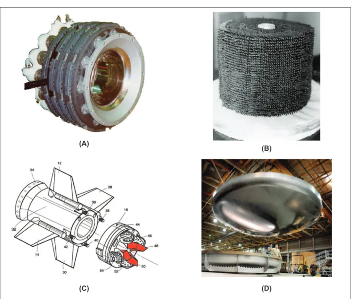
with carbon or ceramic matrices and carbon iber or any other ceramic ibers, as reinforcement, can be used in structural applications. Their outstanding thermomechanical properties overcome the shortcomings of ceramic or metal components. These materials have been largely developed on an empirical basis. Examples of thermostructural composites can be seen in Fig. 1. Carbon iber reinforced carbon/silicon carbide hybrid matrix composites (CRFC-SiC) are considered to be one of the most potential thermostructural materials for aerospace components (e.g. thermal protection systems of reentry vehicles or rocket engine components) (Naislan, 2005; Bouquet, et al., 2003; Christin, 2002). For example, carbon materials are suitable for high temperature structural Received: 07/04/10
materials because of their stable mechanical properties such as hardness and wear resistance in inert atmosphere. They are also light and not corrosive, but they exhibit a brittle like fracture. The traditional 2D preforms have high performance in-plane but they are susceptible to delamination. The multidirectional (3D, 4D, 5D, etc.) preforms exhibit an improved isotropy, good delamination resistance and thick part manufacturing capability (Hinders and Dickinson, 1997). By matching the good in plane properties of 2D composites and the high delamination resistance of multidirectional composites, it is possible to obtain a 2.5D reinforced composite. The 2.5D composites can be needled punched, Z-pinned or stitched, as depicted in Fig. 2. Commercially, thermostructural CRFC-SiC composites can be obtained by the routes as shown schematically in Fig. 3. In this case, the starting point is usually a porous carbon iber reinforced carbon composite. The SiC matrix can be incorporated by the gas phase route (chemical vapor iniltration) from an
organosilicon gas precursor, by iniltration of silicon in a porous carbon iber reinforced carbon composite preform or by polymer impregnation and pyrolysis (PIP), using silicon-based polymers as precursors (Heindenreich, 2007; Guiomar, 1996; Interrante et al., 2002). Considering investment, the PIP route is the simplest technique. The modeling of properties in this work considers the use of PIP method. Typically, CFRC-SiC composites have been made of bidirectional woven fabrics which are stacked together or wound to the desired thickness. Composites having 2.5D reinforcement differ from conventional 3D preforms by their iber volume fraction. For 2.5D iber reinforced composites iber volume fraction in the Z-direction can be up to 10%. For a balanced orthogonal 3D composite, the iber volume fraction can be up to 25% in each iber axis direction. The insertion of Z direction reinforcement in bidirectional composites makes these composites in-plane crack resistant and allows them to endure many heat treatment cycles.
(A)
(C) (D)
(B)
(A)
(B) (C)
Figure 2: (A) Z-pinned preform, (B) needled punched preform, (C) stitched preform.
Figure 3: Commercial process routes used to obtain Carbon iber reinforced carbon-silicon carbide composites.
THE AVERAGE STIFFNESS COMPUTATIONAL METHOD
The properties of composites are designed by the selection of the ibers, their volume fraction, orientation, and architecture in the part. The problem is that the properties of the ibers are frequently altered by processing, and the properties of the matrix are even more sensitive to composite architecture and processing. The prediction and modeling of elastic constants for anisotropic materials and particularly for composites use analytical methods such as the Classical Lamination Theory or Finite Element Analysis (Hyer, 1998). Another way to predict elastic properties of composites take into account their microscopic nature, i.e. their intrinsic microstructure. The appropriate combination of the intrinsic properties of reinforcing ibers and matrix is then assumed. This approach is known as micromechanics, which is a study of the mechanical or thermal properties of composites, in terms of those of constituent materials. General assumptions in micromechanics of composites are: composite are macroscopically homogeneous and orthotropic, linearly elastic, initially stress free, and free of voids. Besides, it is assumed that there is complete bonding at the interface of the constituents and there is no transitional region between them. The displacements are continuous across the iber matrix interphase (there is no interfacial slip). Fibers are homogeneous, linearly elastic, isotropic or orthotropic/transversely isotropic, regularly spaced, perfectly aligned, circular in cross-section and ininitely
long in the longitudinal direction. Matrix is homogeneous, linearly elastic and isotropic. If any temperature effects are considered, the constituent material properties have to be known at a given temperature.
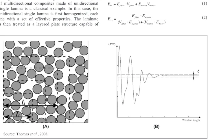
continuum. Of course, all matter is inhomogeneous at some scale, but frequently it is convenient to treat it as homogeneous. A good example is the continuum concept used in continuum mechanics. The Fig. 4A shows a representation of a unidirectional composite cross-section. An increase in the representative volume element (RVE), as showned by dotted lines, leads to a higher degree of homogeneity. Fig. 4B, on the other hand, shows schematically the effect of smoothing a generic asymptotic function that converges to a medium average value as the window length of the RVE is increased. This process of replacing an equation with a highly oscillatory coeficient for a homogeneous (uniform) coeficient is known as homogenization, which is linked to the subject of micromechanics. As a result, homogenization can be viewed as an extension of the continuum concept to materials which possess microstructure. The RVE is the analogue of the differential element in the continuum concept, which contains enough atom, or molecular structure to be representative of that material in homogenization and micromechanics. This RVE contains enough statistical information about the inhomogeneous medium in order to be representative of the material. Therefore, averaging over this element gives an effective property to ibrous composites, and so the homogenization is an essential irst step towards the design and analysis of larger scale and load-bearing structures. The analysis of multidirectional composites made of unidirectional single lamina is a classical example. In this case, the unidirectional single lamina is irst homogenized, each one with a set of effective properties. The laminate is then treated as a layered plate structure capable of
carrying globally applied thermomechanical loads. For the reader, it is useful to review some points related to micromechanics for a better understanding of the average stiffness method, which is the basis of the elastic and thermal properties calculations.
The micromechanics approach is therefore used for elastic and thermal properties calculations. In the Classical Lamination Theory, for instance, the development of a procedure to evaluate stress and strain relations of composite laminates is fundamentally dependent on the fact that their thickness is much smaller than its plane dimensions. Typical thicknesses for individual composite layers can range from 0.10 to 0.25 mm. Consequently, composites having from 5 to 50 layers are considered thin plates and can be analyzed bearing in mind the simpliications of the thin plate theory. In the case of perfectly aligned ibers in a composite, as shown in Fig. 5, assuming linear elastic behavior and perfect adhesion, the Rule of Mixtures is applied, Eq. (1) (Matthews and Rawling, 1994). The equation is a representation of the composite longitudinal elastic modulus (E11). The subscripts refer
to the main reinforcement direction and the direction of applied stress, respectively. The transverse modulus (E22) of the composite is deined by Eq. 2.
E11=Efiber⋅Vfiber+Em atrixVm atrix (1)
E22=
Efiber⋅Em atrix
(Vfiber⋅Em atrix)+(Vm atrix⋅Efiber)
(2)
(A)
(B)
Source: Thomas et al., 2008.
Where Eiber is the modulus of reinforcement, Ematrix is the
matrix modulus, Viber is the volume fraction of ibers, Vmatrix is the volume fraction of matrix.
The in-plane shear modulus (G12) of a unidirectional
composite is given by Eq. (3). Both the transverse and shear modulus are strongly inluenced by the matrix modulus (Gmatrix).
G12 = Gfiber⋅Gm atrix
(Vfiber⋅Gm atrix)+(Vm atrix⋅Gfiber)
(3)
Where Giber is the shear modulus of the iber, Gmatrix is the
matrix shear modulus, Viber is the iber volume fraction, Vmatrix is the matrix volume fraction.
For transversely isotropic materials, properties of the material in directions 2 and 3, from Fig. 5, are almost the same and are transversely isotropic to the direction 1. So, the following identities are valid: E22 = E33, n12 = n13, G12
= G13, and:
G23 =
E22
2⋅(1+v23)
(4)
Where n12, n13 and n23 are Poisson ratios, where the irst
subscript refers to the direction of stress and the second subscript refers to the direction of contraction.
The numerical procedure for the analysis of composites assumes the following hypotheses: (i) regular distribution of ibers in the tow and, (ii) regular assembly of ibers in the unidirectional composite rod. These hypotheses allow iguring out the problem of property estimation in the scope of micromechanics theory of periodicmicrostructure heterogeneous materials, corresponding to two levels of homogenization (Yan, 2003: Pastore and Gowayed, 1994; Gramoll, Freed and Walker, 2001). The irst level
refers to the ibers, which are analyzed independently by the rule of mixture model. Each unidirectional iber forms the composite (Fig. 6A) having the iber volume fraction similar to the packing density. So, the mechanical
properties of the homogenized iber (Fig. 6B) are obtained. The second level refers to “ictitious” multidirectional composite, having tows of ibers (rods) homogenized (Fig. 6C). The regularly spaced ibers in the composites allow to determine the representative volume element (Fig. 6D), and to evaluate the homogenized material (Fig. 6E) in terms of macroscopic quantities (global) (Pastore and Gowayed, 1994; Gramoll, Freed and Walker, 2001). 3
1 2
Figure 5: Schematic representation of a unidirectional (1D) composite and main axis.
b
a c 1
2
3
θ
α X
Y
Z
Figure 7: Local axis system (1, 2, 3) and global axis system (x, y, z) of coordinates, and 1, 2 and 3 are orthogonal. This model is described as “Fabric Geometry Model - FGM” (Pastore and Gowayed, 1994), which is based on the idea that the elastic properties of the composite can be calculated as a function of the relative proportion of the properties of the ibers, at speciic directions, and the matrix. In summary, the composite is analytically divided in volume elements (unit cell) composed of composite rods. Each unidirectional reinforced rod has its own iber volume fraction and from their vetorially oriented contributions forms the properties of the homogenized composite. The properties of each direction, represented by the composite rod in the unit cell, are calculated and the results for elastic constants refer to the local axis system (1-2-3), as shown in Fig. 7.
Figure 6: The hierarchical constitutive model: (A) unit cell, (B) composite rod, (C) representative unit of the iber as unidirectional reinforcement, (D) preform representation and unit cell of the composite, (E) homogenized composite.
(A)
(B)
(C) (D)
The axis transformation from the stiffness matrix (C) and compliance (S) can be obtained by means of stress/ strain transformation axis (Pastore and Gowayed, 1994;
Gramoll, Freed and Walker, 2001). The resulting equation
from axis transport for the stiffness matrix can be obtained as shown in Eq. (5).
[Cglobal]=[K][T][Clocal][K] (5)
Where [Cglobal] is the matrix stiffness in the global axis
system (x,y,z), [K] is the stress/strain transportion matrix,
[Clocal] is the stiffness matrix in the local axis system
(1-2-3), and T is the transformation matrix.
The transformation of constants from the local system to the global system is done by a transformation matrix composed of entities related to direction cosines (angles
θ and α, respectively related to elevation and azimuth) from orientation of the rods. So, due to orthogonality only the Te matrix is needed, which is represented in Eq. 6.
The li, mi and ni are direction cosines components of the
unit basis vectors associated with the principal axes of the ibrous reinforcement.
(6)
In Fig. 7 the axis 1 is related to vector r1, which is the unit vector associated with iber axis (l
1, l2, l3), the axis 2
is related to vector r2, which is the unit vector associated with #2 direction of the iber (m1, m2, m3), and axis 3 is
related to vector r3, which is the unit vector associated with
#3 direction of the iber (n1, n2, n3). The vector r
1 can be
known by solving the geometrical relationship represented by Eq. (7).
The other two vectors can be known by solving through geometric relationships. Because they are mutually orthogonal, it can be proved that r
1.r2 = 0, r2.r3 = 0 e r1.r3
= 0. As they are direction cosines vectors, ||r
1|| = ||r2|| =
||r
3|| = 1, and a, b and c are the edges of the unit cell.
(7)
Where (diagonal)2= a2 + b2 + c2.
The contribution from each rod in the direction of the global axis system is done by the superposition of the stiffness matrix or lexibility matrix transposed for the global system, as shown by Eq. 8 (Pastore and Gowayed, 1994).
(8)
Where Ccomp is the composite stiffness matrix, V iber
is the total iber volume fraction, V
iber-i is the relative
iber volume fraction from the i-esime unidirectional composite rod, Ci is the stiffness of the i-esime unidirectional composite rod and n is the number of
unidirectional composite rods.
The thermal properties (thermal conductivity and coeficient of thermal expansion) were also calculated on the basis of average properties from the individual constituents of the composite by using the Fabric Geometry Model – FGM. During transient heat low, transverse heat low between the iber and the matrix is expected to occur. This is the case for materials with signiicantly different thermal conductivities. If their interfaces are negligible in thickness, the longitudinal thermal conductivity of the composite will only be affected by the ibers and the matrix thermal conductivities, and will be unaffected by the ibers/ matrix interface according to Eq. 9.
(9)
Where kc(//) is the thermal conductivity parallel to the iber direction, kfiber and kmatrix are the thermal conductivity of the ibers and matrix, respectively and
Vfiber and Vmatrix are the volume fraction of the ibers and
matrix, respectively. The thermal conductivity in the perpendicular direction of the composite is calculated by means of Eq. 10.
(10)
Where kc (^) is the thermal conductivity perpendicular to the iber direction, kiber (//) is the thermal conductivity parallel to the iber, .kmatrix(//) is the thermal conductivity parallel to the matrix, and Viber and Vmatrix are the volume
fraction of the ibers and matrix, respectively.
the coeficient of thermal expansion of a composite, with a reasonable approximation, to follow the simple rule of mixtures. However, because of the differences in the thermal expansivities of the phases (iber and matrix), a state of micro-stress often exists between them, inluencing the thermal expansion behavior of the body and giving rise to discrepancies. Thus, its thermal expansion coeficient does not follow the rule of mixtures (Thomas et al., 2008; Mukerji, 1993).
Karadeniz and Kumlutas (2007) investigated the existing theories for prediction of coeficient of thermal expansion based on micromechanics and inite element analysis, considering the iber volume fraction ranging from 10 to 90% for the studied composites (Mukerji, 1993). The theories agreed quite reasonably for calculation of the thermal expansion coeficient in the main iber axis direction (α1), at least for ordinary
unidirectional polymer matrix composites, even compared with sophisticated modeling techniques, such as inite element calculations, for a range of iber volume fractions (Mukerji, 1993). Nevertheless, for the transverse direction (α2), the rule of mixtures seems to
have a better agreement with inite element calculations than other micromechanical theories. The coeficient of thermal expansion for composite materials is a function of stress and strain in the matrix and iber, according to Eq. (11).
(11)
Considering ecomp = ematrix = eiber, in the iber direction, the
Eq. (12) is obtained.
(12)
If there is free expansion in the direction of the iber, e1 = α1.DT, where α1, it is according to Eq. (13) as follows:
(13)
For the transverse direction to the iber axis, the coeficient of thermal expansion (α2) is obtained as shown in Eq. (14),
as follows:
(14)
RESULTS FOR AVERAGE STIFFNESS 2.5D CARBON FIBER REINFORCED C/SIC HYBRID MATRIX COMPOSITES
For the prediction of the mechanical properties of 2.5D CFRC-SiC composites through the micromechanics method, it is necessary initially to establish representative properties of the carbon iber, the carbon matrix and the silicon carbide matrix. Mechanical properties of carbon ibers are well documented in the literature (Peebles, 1994; Inagaki, 2001; Asakuma et al., 2003). Table 1 shows the properties of carbon iber, SiC matrix and carbon matrix found in literature. The best value for the properties of a carbon matrix can rely on synthetic graphite mechanical and thermal properties (Inagaki, 2001). Synthetic graphites are obtained by a controlled pyrolysis process, up to 2500oC, from a mixture of pitch and coke. In relation
Table 1: Properties of carbon iber, SiC matrix and carbon matrix reported in the literature and from manufacture’s data
Temperature (°C) Carbon iber SiC matrix* Carbon matrix
RT 1000 1200 RT 1000 1200 RT 1000 1200
Elastic modulus (GPa)
Longitudinal 230 230 230 225 225 225 10 10 10
Transversal 20 20 20 225 225 225 10 10 10
Shear modulus (GPa) 12 12 12 75 75 75 4.2 4.2 4.2
Poisson Ratio n 0.18 0.14 0.18
Density (g/cm3) 1.78 2.55 1.80
k (W/m.K)
Longitudinal 8.40 1.768 120 60 55
Transversal 0.84 1.377
α (10-6/°C)
Longitudinal 18 0.164 -0.6 1.5 2.0
Transversal 1.2
*calculated based on Nicalon CG iber.
to other carbon matrix materials obtained from gas phase deposition or thermoset resin pyrolysis, the mechanical properties of synthetic graphite are lower. A reasonable estimation of the elastic properties of a carbon matrix based on pitch coke, which is nearly the same of other graphitic materials, was reported by Asakuma (Asakuma
et al., 2003).
Silicon carbide can be obtained by a number of techniques, and the most common are hot pressing and chemical vapor deposition. In this manner, their properties can vary greatly depending on the method of preparation and the inal microstructure obtained. But only few works have mentioned properties of silicon carbide obtained by any of the silicon polymer pyrolysis methods, possibly because of the dificulties of getting representative samples for traditional mechanical tests, such as tensile strength. On the other hand, mechanical properties for hot pressed silicon carbide only rely on lexural strength or compressive strength, and respective modulus, mainly because covalent ceramics are not suitable for use under tensile loads. Reported values for lexural strength of hot pressed SiC can be up 450 MPa (Mukerji, 1993). Somiya and Inomata (1992) found for a CVD-SiC material, tested under three-point bending values in the range of 200-690 MPa, and in this work a tensile strength of 590 MPa was also reported. The best combination of properties was obtained for CVD-SiC having a 1.5-mm grain size (Munro, 1997).
The Young’s modulus of typical hot-pressed SiC materials is reported in the range of 275-465 GPa. The characterization of tensile strength of SiC, as any other covalent ceramic, is hardly dificult because they are prone to surface defects due to machining and by other inadequate specimen preparation procedures which leads to misleading measurements. Besides, tensile strength of SiC has a low value compared to their lexural and compressive strength. This is the reason why the uses and the mechanical characterization of SiC are practically done under lexure or compressive loading. In fact, the tensile tests lead to conservative results in relation to the other types of tests, such as lexure tests, and, as a consequence, the tensile strength can be much lower than lexural strength. Munro (1997), for instance, found a tensile strength of ~250 MPa for a hot pressed α-SiC, from 25oC to 1400oC.
The best known SiC material obtained from silicon polymer pyrolysis is the Nicalon iber (Yajima et al., 1979). Although the Nicalon SiC iber varies in composition, it represents the properties of a typical polymer ceramic silicon carbide matrix. The chemical composition of Nicalon ceramic grade iber has typically ~65% SiC, ~15% carbon and ~20% SiO2. At room temperature, its Young’s
modulus is ~200 GPa and the tensile strength is 3.0 GPa. If considered isotropic, the shear modulus of Nicalon ceramic grade iber is ~87 GPa, considering the relation E=2G(1+n), but experimental results show values near 75 GPa for ibers processed at 1200oC. Increasing the test
temperature up to 1200oC causes no noticeable changes on
Young’s modulus and in the shear modulus (Villeneuve and Naslain, 1993). Studies conduced by Sorarù, Dallapiccola and Dándrea (1996) on SiCxOy glasses synthesized by the
sol-gel method found a Young’s modulus of 115 MPa for these materials. For SiCxOy glasses, the properties beyond
1200oC fall rapidly. The prediction of elastic and thermal
properties for carbon iber reinforced carbon-SiC hybrid matrix was done by taking the properties of Table 1, for carbon iber, SiC matrix and carbon matrix. In this case, the properties of the SiC matrix were considered as similar to the SiC iber which is the best approximation for a typical amorphous polymer ceramic Si-C-0 matrix.
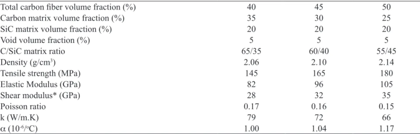
For composites made with ceramic matrices, processed by the polymer impregnation method, porosity in the range of 5 to 20% is usually attained (Rice, 1999). In this work, for comparison purposes and for good of prediction, it is considered a composite having ~5% volume porosity, and carbon iber volume fraction of 40, 45 and 50%. The carbon matrix volume fraction will vary from 35, 30, and 25%, respectively to carbon iber volume fraction, as shown in Table 2. The volume of SiC polymer ceramic matrix is kept, also for comparison purposes, at 20% volume fraction. In the calculations, the out-of-plane Z iber addition is considered to be uniformly distributed throughout the composite. So, properties of the CFRC-SiC composite can be varied by taking the relative proportions of carbon and silicon carbide, according to the rule of mixture, as shown in Table 2. It is important to point out that mechanical properties are approximately constant from room temperature to 1200oC for these composites.
From input parameters from Table 1 and Table 2, the output parameters processed by the FGM model such as local resilient matrix and stiffness matrix, and global stiffness matrix, are obtained, as shown in Table 3, related to the direction cosines of a unidirectional composite. Results from Table 3 leads to elastic and thermal properties showed in Table 4. The elastic modulus for bidirectional Carbon Fiber Reinforced C/SiC Hybrid Matrix was also calculated, for comparison purposes.
Table 2: Properties of hybrid matrices of carbon/silicon carbide related to volume fractions of carbon and silicon carbide used for modeling the properties of CFRC/SiC-modiied composites
Total carbon iber volume fraction (%) 40 45 50
Carbon matrix volume fraction (%) 35 30 25
SiC matrix volume fraction (%) 20 20 20
Void volume fraction (%) 5 5 5
C/SiC matrix ratio 65/35 60/40 55/45
Density (g/cm3) 2.06 2.10 2.14
Tensile strength (MPa) 145 165 180
Elastic Modulus (GPa) 82 96 105
Shear modulus* (GPa) 28 32 35
Poisson ratio 0.17 0.16 0.15
k (W/m.K) 79 72 66
α (10-6/oC) 1.00 1.04 1.17
*calculated by E=2G(1+n).
Local resilient matrix
0.00597015 -0.00110448 -0.00110448 0 0 0
-0.00110448 0.0297619 -0.00748348 0 0 0
-0.00110448 -0.00748348 0.0297619 0 0 0
0 0 0 0.047619 0 0
0 0 0 0 0.0744908 0
0 0 0 0 0 0.047619
Local stiffness matrix
170.6299 8.4592 8.4592 0 0 0
8.4592 36.2871 9.4381 0 0 0
8.4592 9.4381 36.2871 0 0 0
0 0 0 21.0000 0 0
0 0 0 0 13.4245 0
0 0 0 0 0 21.0000
Composite stiffness matrix
170.6299 8.4592 8.4592 0 0 0
8.4592 36.2871 9.4381 0 0 0
8.4592 9.4381 36.2871 0 0 0
0 0 0 21.0000 0 0
0 0 0 0 13.4245 0
0 0 0 0 0 21.0000
Table 3: Direction cosines, transformation matrix, local resilient matrix, local stiffness matrix and composite stiffness matrix for a CFRC-SiC unidirectional composite model
Transformation matrix
1 0 0 0 0 0
0 1 0 0 0 0
0 0 1 0 0 0
0 0 0 1 0 0
0 0 0 0 1 0
0 0 0 0 0 1
majority of applications, the Z reinforcement has the main purpose of holding together the bidirectional stacks of iber reinforcement fabrics, improving interlaminar shear and through-the-thickness fracture toughness than truly improve through-the-thickness elastic or thermal properties. So, with a reasonably approximation, the calculated properties using the Fabric Geometry Model can be compared with 2D CRFC-SiC composites. For instance, Wang et al. (2008) found for a 2D CFRC-SiC composite processed by CVI technique, having 40%/volume of ibers and 13% porosity, a Young’s modulus of 95±9 GPa. Arendts and Maile (1998)
reported a Young’s modulus of 70-80 GPa for a 2D CRFC-SiC composite obtained by polymer pyrolysis having 8%/ volume porosity, and a Young’s modulus of 50-70 GPa for a 2D CRFC-SiC composite processed by liquid silicon iniltration, having 5%/volume porosity and 40% iber volume fraction. Nie et al. (2008) found a Young’s modulus of 81 GPa for a 2D CFRC-SiC matrix, obtained by the CVI technique, having 40% volume fraction of carbon ibers and 11%/volume porosity. In the same work, stitched carbon iber fabrics processed in the same way exhibited a Young’s modulus of 62-64 GPa. Nie et al. (2009) also found a Young’s modulus of 75±4 GPa for a needled carbon iber
densiied with a SiC matrix, obtained by the CVI technique. These properties can be compared with those shown in Table 5 and Table 6. It is well known that Young’s modulus of composites is mainly dependent on iber’s properties and on their volume fraction.
In the present work, the calculated elastic modulus for unidirectional CFRC-SiC composites, in the iber direction, ranges from 140 to 170 GPa, and from 36 to 33 GPa, Table 4: Properties of unidirectional (1D) carbon iber
reinforced C/SiC hybrid matrix
Total carbon iber
volume fraction (%) 40 45 50 C/SiC matrix ratio 65/35 60/40 55/45
E11 141 156 167
E22 36 35 33
E33 36 35 33
G12 20 21 21
G23 14 14 13
G13 20 21 21
υ12 0.18 0.18 0.18
υ13 0.18 0.18 0.18
υ23 0.25 0.25 0.25
k11 57 50 45
k (W/mK) k22 35 30 25
k33 35 30 25
α11 0.12 0.70 1.05
α (10-6/°C) α
22 0.68 0.34 0.63
α33 0.68 0.34 0.63
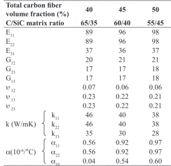
Table 5: Properties of bidirectional (2D) carbon iber reinforced C/SiC hybrid matrix
Total carbon iber
volume fraction (%) 40 45 50 C/SiC matrix ratio 65/35 60/40 55/45
E11 89 96 98
E22 89 96 98
E33 37 36 37
G12 20 21 21
G23 17 17 18
G13 17 17 18
υ 12 0.07 0.06 0.06
υ 13 0.23 0.22 0.21
υ 23 0.23 0.22 0.21
k11 46 40 38
k (W/mK) k22 46 40 38
k33 35 30 28
α11 0.56 0.92 0.97
α(10-6/°C) α
22 0.56 0.92 0.97
α33 0.04 0.54 0.60
perpendicularly to iber direction, considering a iber volume fraction from 40 to 50%, respectively. For the 2D CFRC-SiC composite, elastic modulus range from 90 to 100 GPa, considering a iber volume fraction from 40 to 50%. For the 2D CFRC-SiC composites having Z-reinforcement ranging from 2 to 6%, elastic modulus range from 80 to 95 GPa in the plane of reinforcement, and from 43 to 57 GPa in the out-of-plane direction, considering a total iber volume fraction from 40 to 50% in the composite. Heidenreich (1997) resumed data on properties of C-SiC composites obtained from many companies. For instance, C-SiC composites obtained by CVI technique, having 45% iber volume fraction, had the elastic modulus reported as 90-100 GPa. In the same work, C-SiC composites obtained by liquid polymer iniltration and by liquid silicon iniltration had the elastic modulus reported as 65 GPa (Heidenreich, 2007). Although these data are from various material types, it is possible to infer that the calculated values from this work, as shown in Tables 5 and 6, are reasonably in the range of those found in the literature.
The thermal properties depend on the axis of measurement and are mainly inluenced by the carbon iber. Calculation for thermal conductivity of CRFC-SiC composites (Table 6) are in the range from 32 to 46 W/m.K. The survey of properties of C-SiC composites, obtained by Heidenreich (1997), shows more conservative results for thermal conductivity, which are in the range of 5 to 20 W/m.K, although values up to 40 W/m.K can be found. These differences can be attributed to the differences on the manufacturing method and the presence of pores and microcracks which are not exactly accounted in Fabric Geometry Model. Thermal expansion coeficients calculated by the Fabric Geometry Model for
the CFRC-SiC composites are in the range of 0.15x10⁻⁶/°C
to 1x10⁻⁶/°C, which are in the range (-1x10⁻⁶/°C to 6x10⁻⁶/°C)
showed in the survey of properties of C/SiC materials of the work of Heindenreich (2007).
CONCLUSION
This work described a simple method for estimation of the elastic and thermal properties of 2.5D carbon iber reinforced carbon-SiC hybrid matrix composites. These materials are the state-of–the-art composites for use in thermal protection systems. The Z-direction reinforcement allows higher delamination resistance and endurance on thermal stresses generated by heat treatment processing, and also the interlaminar fracture toughness is improved. Mechanical and thermal properties of 2.5D CRFC-SiC composites were calculated based on composite average stiffness micromechanics. The modeling of properties by this simple method allows avoiding costly testing and reducing time consuming specimen preparation.
Mechanical properties of composites are iber dominated. Calculations were done by considering the total carbon iber volume fraction in the range of 40 to 50%, which are commonly found in carbon and ceramic composites reinforced with carbon ibers. The addition of only 2% of ibers out of the main plane of reinforcement increases the elastic modulus in the out-of-plane direction by about 20%.
An increase in the carbon iber volume fraction from 40 to 50%, results in higher elastic properties, but nevertheless decreases the thermal conductivity. The calculated in-plane Young’s modulus is in the range of 84 to 94 GPa,
and the out-of-plane Young’s modulus is in the range of 43 to 57 GPa. The calculated shear modulus is in the range of 17 to 24 GPa, regardless of the plane of shear stress.
The calculated thermal conductivity of 2.5D carbon iber reinforced carbon-SiC hybrid matrix composites was found to be in the range of 32 to 46 W/m.K, and the calculated coeficient of thermal expansion was in between 0.15.10-6/°C
to 0.94.10-6/°C. These results agreed in some extent to values
found in the literature for similar materials.
The knowledge of the envelope of elastic and thermal properties of carbon and ceramic composites made with carbon ibers allows ab initio modeling thermoelastic properties of composites. These properties can be easily calculated by taking individual properties of each component (iber and matrix) and the relative proportions of these components in the composite which is the essence of the homogenization theory.
REFERENCES
Arendts, F.J., Maile, K., 1998, “Thermomechanicshes Verhalten Von C/C-SiC. Arebeits-und Ergebnisbericht SFB” 259.
Asakuma, Y., et al., 2003, “A New estimation method of coke strength by numerical”, Multiscale Analysis ISIJ International, Vol. 43, No 8, pp. 1151-1158.
Bouquet, C., et al., 2003, “Composite technologies development status for scramjet applications”, In: 12th AIAA international space planes and hypersonic systems
Table 6: Properties of 2.5D carbon iber reinforced C/SiC hybrid matrix, having 5% volume porosity, from RT to 1200°C
Total iber volume fraction (%) 40 45 50
C/SiC matrix relation 65/35 60/40 55/45
Fiber volume Z direction (%) 2 4 6 2 4 6 2 4 6
E11 86 83 79 91 87 84 94 90 86
E22 86 83 79 91 87 84 94 90 86
E33 43 48 53 44 50 56 45 51 57
G12 21 22 22 22 23 24 23 24 24
G23 17 17 17 18 23 18 23 24 24
G13 17 17 17 18 18 18 19 19 19
n12 0.09 0.11 0.13 0.09 0.11 0.12 0.08 0.10 0.12
n13 0.19 0.17 0.14 0.18 0.16 0.12 0.18 0.15 0.12
n23 0.19 0.17 0.14 0.18 0.16 0.14 0.18 0.15 0.13
k11 46 45 45 42 42 42 40 39 39
k (W/mK) k22 46 45 45 42 42 42 40 39 39
k33 37 37 39 34 35 36 32 33 34
α11 0.50 0.50 0.50 0.90 0.90 0.88 0.96 0.94 0.94
α (10-6/oC) α
22 0.50 0.50 0.50 0.90 0.90 0.88 0.96 0.94 0.94
α33 0.15 0.22 0.30 0.66 0.72 0.77 0.74 0.80 0.84
and technologies, Norfolk, Virginia, December 15-16, AIAA-2003-6917.
Christin, F., 2002, “Design, fabrication, and application of thermostructural composites (TSC) like C/C, C/SiC, and SiC/SiC composites”, Adv Eng Mater, Vol. 4, No 12, pp.
903-912.
Gramoll, K.C., Freed, A. L., Walker, K. P., 2001, “An overview:
of self-consistent methods for iber reinforced composites”,
NASA-TM 103713.
Guiomar, N., 1996, “Caractérisation physico-chimique et microstructurale de ceramiques sic issues de polymeres precurseurs application a lélaboration de composites a matrices ceramiques”, Tese de Doutorado, Université Paris 6, 212 p.
Heidenreich, B., 2007, “Carbon ibre reinforced sic materials based on melt iniltration”, 6th International Conference on High Temperature Ceramic Matrix Composites, New Delhi , India, 6 p, Sep 4-7.
Hinders, M.; Dickinson, L., 1997, “Trans-laminar (TLR) reinforced composites”, NASA CR-204196.
Hyer, M.W., 1998, “Stress Analysis of Fiber-Reinforced
Composite Materials”, McGraw Hill Intl. Edition, USA.
Inagaki M., 2001, “Applications of polycrystalline graphite”, In: Graphite and Precursors, P. Delhaeès, Gordon and Breach Science Pub., UK.
Interrante L.V., et al., 2002, “Silicon-based ceramics from polymer precursors”, Pure Appl. Chem., Vol. 74, No 11, pp. 2111-2117, 2002.
Karadeniz Z.H., Kumlutas, M., 2007, “A numerical study on the coeficients of thermal expansion of iber reinforced composite materials.”, Composite Structures, Vol. 78, No 1,
pp. 1-10.
Matthews F.L., Rawling R. D., 1994, “Composite materials: engineering and science”, Cambridge - UK, Chapman & Hall.
Mukerji, J., 1993, “Ceramic Matrix Composites”, Defence Science Journal, Vol. 43, No 4, pp. 385-395.
Munro, R.G., 1997, “Material Properties of a Sintered α-SiC”. Journal of Physical and Chemical Reference Data, Vol. 26, No 5, p. 1195-1203.
Naislan, R., 2005, “SiC-matrix composites: nonbrittle ceramics for thermo-structural application”, Int J Appl Ceram Techn, Vol. 2, No 2, pp. 75-84.
Nie, J. et al., 2008, “Effect of stitch spacing on mechanical properties of carbon/silicon carbide composites”, Composites Science and Technology, Vol. 68, pp. 2425-2432.
Nie, J. et al., 2009, “Microstructure and tensile behavior of multiply needled C/SiC composite fabricated by chemical vapor iniltration”, Journal of Materials Processing Technology, Vol. 209, pp. 572-576.
Pastore, C.M., Gowayed, Y. A., 1994, “A self-consistent fabric geometry model: modiication and application of a fabric geometry model to predict the elastic properties of textile composites”. Journal of Composites Technology and Research, Vol. 16, No 1, p. 32-36C.
Peebles, L.H., 1994, “Carbon ibers: formation, structure, and properties”, CRC Press, Boca Raton.
Rice, R.W., 1999, “Effects of amount, location, and character of porosity on stiffness and strength of ceramic iber composites via different processing”, Journal of Materials Science, Vol. 34, pp. 2769-2772.
Somiya, S., Inomata, Y., 1992, “Silicon Carbide Ceramics-2, Gas Phase Reactions, Fibers and Whisker Joining”, Elsevier Applied Science, London.
Sorarù, G. D., Dallapiccola, E., Dándrea, G., 1996, “Mechanical characterization of sol-gel-derived silicon oxycarbide glasses”. Journal of the American Ceramic Society, Vol. 79, No 8, pp. 2074-2080.
Thomas, M. et al., 2008, “Estimation of effective thermal
conductivity tensor from composite microstructure images”, 6th International Conference on Inverse Problems in Engineering: Theory and Practice, Journal of Physics, Conference Series 135, 012097.
Villeneuve, J.F., Naslain, R., 1993, “Shear moduli of carbon, Si-C-O, Si-C-Ti-O and Alumina Single Ceramic Fibers as Assessed by Torsion Pendulum Tests”, Composites Science
and Technology, Vol. 49, pp. 191-203.
Wang, Y., et al., 2008, “Characterization of tensile behavior of a two-dimensional woven carbon/silicon carbide composite fabricated by chemical vapor iniltration”, Materials Science and Engineering, A 497, pp. 295-300.
Yajima, S., et al., 1979, “Development of a SiC iber with high tensile strength”, Nature, Vol. 261, pp. 683-685.