Analysis and Simulation of Reduced FIR Filters
Lj. Radic and W. Mathis
FG Theoretische Elektrotechnik, Institut f¨ur Theoretische Elektrotechnik und Hochfrequenztechnik Universit¨at Hannover, Appelstraße 9A, 30167 Hannover, Germany
Abstract. High order FIR filters employ model reduction techniques, in order to decrease power consumption and time delay. During reduction high order FIR filters are converted into low order IIR filters preserving stability and phase lin-earity as main features. Matlab simulations of an audio sys-tem with these reduced filters are presented. Furthermore, the influence of order on power consumption is discussed.
1 Introduction
In problem area like model order reduction several reduc-tion methods have been developed in the last two decades. A classification of these methods can be given by referring to the domain where the high-order and low-order models have to be represented either in frequency or time domain. The most frequently employed model reduction methods for linear, stable, continuous- or discrete-time systems are the Balanced Truncation Model Reduction (Beliczynski et al., 1992) (BMT), Singular Perturbation Model Reduction (SPR) (Aldhaheri, 2000) and Optimal Hankel Norm Approximation (OHN) (Beliczynski et al., 1994). These methods operating in the state-space domain of the original model lead to the derivation of a low-order model with fewer state variables. Our starting point for applying model reduction methods is a novel binary zero-position coding algorithm (ZePoC) (Stre-itenberger and Mathis, 2002a). This algorithm is developed to convert audio signals into binary signals eliminating high frequency distortions. Hardware implementation of ZePoC system includes FIR filters as main building blocks (Streit-enberger et al., 2001), where phase linearity is essential. It is well known that phase linear FIR filters allow distortion free transmission of signals, and they are widely used due to advanced design tools. However, the main drawback of FIR filters is their high order. Model reduction techniques offer a solution for designing filters with low order preserving phase Correspondence to:Lj. Radic
(radic@tet.uni-hannover.de)
linearity and stability (Prenbo and Silverman, 1982). While model reduction techniques give IIR filters with lower order, their implementation may lead to problems of coef-ficients presentation. We will show that the coefcoef-ficients of the reduced IIR filters can be represented by second-order sections and implemented with the same digital signal pro-cessor (DSP) with two’s complement fix point arithmetic as in the case of the original FIR filters.
In addition, we are going to discuss the power consumption of the reduced filters. There are different approaches to this problem. One way is to reduce the amount of switched ca-pacitance during its operation (Chandrakasan and Brodersen, 1995). Another way is to reduce filter hardware decreasing the number of its digital circuits. In this sense we observe correlation between reduction methods and the complexity of the reduced filter.
In our paper we will show in an implicit manner the influ-ence of conventional model reduction methods to the power consumption. Furthermore we will show with Matlab simu-lations that these reduced IIR filters preserve the quality of audio signals of the ZePoC system with the original FIR fil-ters, while power consumption is reduced.
2 Application of the model reduction techniques
Fig. 1.Symbolic presentation of the ZePoC algorithm. All hardware elements with FIR filter structure are marked with circles.
0 5 10 15 20
−4 −3 −2 −1 0 1 2 3 4
x 10−5
frequency [kHz]
error [s]/Ts
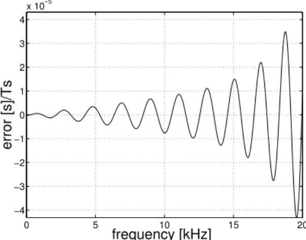
Fig. 2. Group delay error of the 8-times up sampling IIR filters in pass band. Error is scaled by sampling rateTs=1/fs,fs=384 kHz.
filters isfs=384 kHz. The last up-sampling block is 4-times up-sampling FIR filter that carry out the signal processing al-gorithms including implicit zero-computation to an accuracy of 16 bits. The order of this filter is 34 with the sampling frequencyfs=1536 kHz.
For audio signals only the frequency range between [0, 20 kHz] is significant in the pass band of the filters.
Analysis of magnitude response error and group delay er-ror in Radi´c and Mathis (2004a) for described filters showed that the best results were archived by SPR. This method is applicable to systems that can be heuristically decoupled into a slow subsystem and a fast one. Rejection of very fast modes from a model gives a new system consisting of a slow part that can be considered dominant for a description of the full behaviour.
All reduced filters obtained by SPR techniques are IIR filters with quasi-linear phase in pass band. We are going to discuss the size of ripple shape of group delay error of each reduced filter, because it shows the deviation of phase from exact linearity. Indeed, the group delay errors increase with frequency in pass band, as it is shown in Fig. 2, for 8-times up sampling filters that are reduced to order 34. For frequencies larger than 17 kHz this ripple reaches values larger than 2·10−5. Therefore, the input signal with fre-quencies between 17 kHz and 20 kHz can be more interfered.
0 5 10 15 20 25 30 35 40 −4
−3 −2 −1 0 1 2 3 4x 10
−5
frequency [kHz]
error [s]/Ts
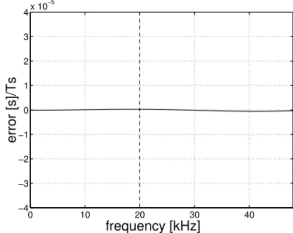
Fig. 3. Group delay error of the low pass IIR filters in pass band. Error is scaled by sampling rateTs=1/fs,fs=384 kHz. The dashed line marks the highest input signal frequency, 20 kHz.
The LPFs are reduced to order 37 and have very small group delay error up to frequency 20 kHz, see Fig. 3. For the most critical frequencies, around 20 kHz, the ripple of the scaled group delay error is less than 10−5and has small influence on the input signals.
The last 4-times up sampling filter reduced to the order 15 has very small group delay error in pass band, particularly for the input signal range marked by dashed line in Fig. 4. The magnitude response error for all filters is in the pass band smaller than−150 dB, so that the error is imperceptible for audio signals (Radi´c and Mathis, 2004b).
3 Power consumption of the reduced filter
the sample frequency (Erdogan et al., 2001). Therefore, for achieving low-order it has to be minimised one or more of the parametersNi,Ci,Vdd andfs. In this paper we analyze the power consumption of a reduced filter through the num-ber of operations,Ni, like multiplying and adding, because they are directly impacted by reduction of filter order. The number of multipliers and adders is related to the se-lected filter presentation and each of them needs some energy
EM andEA respectively. Therefore the power consumption can be presented as a function of these two energies
P =F (NMEM, NAEA). (2)
NM andNA are numbers of multiplying and adding opera-tions, respectively. We are not going to discuss the nature of the functionF but the influence of the order reduction on
NM andNA.
The multipliers are one of the major bottlenecks governing the performance of a DSP algorithm. Indeed, the power dissipated within a multiplier represents a significant pro-portion of the overall power dissipated by the DSP device (Abu-Khater et al., 1996). Furthermore we will consider and influence of the number of adders because their number depends on size of reduction.
3.1 Relations between order reduction and power con-sumption of the reduced filter
In this section we investigate the influence of model reduc-tion to the complexity of the reduced filters and to compare the power consumption of the reduced IIR filter with the orig-inal FIR filters. First we are going to discuss the complexity and power consumption of the original linear phaseNF I Rth order FIR filters. These FIR filters have a symmetric or an-tisymmetric impulse response, so that|NF I R/2| two-input multipliers are required. “| |” stands for oddNF I R/2 rounded to the nearest larger integer. The number of two-input adders is equal to the order of such a filter. Therefore, the power consumption of an FIR filter according to Eq. (2) is
PF I R=F (|
NF I R
2 |EM, NF I REA2). (3)
It is well known that the parallel structure has problems with finite word length representations (Vaidyanathan, 1993). Due to infinite word length requirements we will not discuss parallel structure as a possible solution for the representation of the reduced filters. Further, a filter represented by DF is implemented such that for each multiplication both inputs of the multiplier receive new data. This causes higher level
0 10 20 30 40 −4
−3 −2
frequency [kHz]
Fig. 4. Group delay error of the 4-times up sampling IIR filter in pass band. Error is scaled by sampling frequency Ts=1/fs, fs=1536 kHz. The dashed line marks the highest input signal fre-quency, 20 kHz.
of switching activity within the multiplier leading to higher power consumption (Arslan and Erdogan, 2002). The other two interesting structures TDF and SOS will be discussed, because of their low complexity (Tietze and Schenk, 1986), which may lead to low power consumption.
The TDF of an NI I Rth order IIR filter is characterized by 2NI I R-1 unique coefficients and employs 2NI I R+1 two-input multipliers and 2NI I R two-input adders. In this filter representation delay units are placed between adders so that the multipliers can be feed simultaneously. It results in a re-duction of the switching activity of the multiplier data inputs since the date input remains unchanged for a significant num-ber of multiplication operations.
Comparing the number of multipliers for a linear phase FIR filter and its associated reduced IIR filter, the degree of re-duction for which a number of multipliers for TDF is lower than for original filter, can be calculated using the relation
pNF I R=NI I R (4)
in the expression where the numbers of multipliers is com-pared
2pNF I R+1≤
NF I R
2 , (5)
The coefficientp indicates the degree of reduction. If we assume that 1/2NF I R≪1/4 thenp≈25%. The FIR filter has to be reduced by more than 75% to verify a lower number of multipliers for the reduced IIR filter.
In the following the power consumption of the reduced filter presented by SOS can be presented as
PI I RSOS=F (|NI I R
2 |5EM,|
NI I R
2 |EA5), (6)
where EA5 is energy of five-input adder. The number of
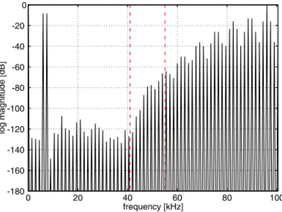
Fig. 5.Spectrum of output signal of ZePoC system with FIR filters, where signal contains f1=6 kHz and f2=7.5 kHz frequencies.
0 20 40 60 80 100
−180 −160 −140 −120 −100 −80 −60 −40 −20 0
frequency [kHz]
log magnitude [dB]
Fig. 6.Spectrum of output signal of ZePoC system with IIR filters, where signal contains f1=6 kHz and f2=7.5 kHz frequencies.
multipliers of SOS is not necessarily lower for each reduced IIR filter than for the original FIR filter. If the order of an IIR filter is presented as percentagepof the order of an FIR filter we can calculate value of the constantpas
|pNF I R
2 |5≤ |
NF I R
2 |. (7)
From Eq. (7)p has to be equal or smaller than 20%. Ac-cording to Eq. (4) the FIR filters have to be reduced at least by 80%, so that the second order section presentation of re-duced IIR filter requires less number of multipliers.
4 Simulation of the ZePoC system with reduced low pass IIR Filters
The representation of data and coefficients in DSPs plays also very important role in reducing power consumption of the filters. There are two common methods of their represen-tation two’s complement and sign-magnitude represenrepresen-tation (?). We decided to use the same 24 bits DSP and to represent the coefficients of reduced filters in two’s complement, because the two’s complement was used for representation of the original FIR filters coefficients.
Fig. 7.Spectrum of output signal of ZePoC system with FIR filters. The signal contains f1=18.5 kHz and f2=19.5 kHz frequencies.
0 20 40 60 80 100
−180 −160 −140 −120 −100 −80 −60 −40 −20 0
frequency [kHz]
log magnitude [dB]
Fig. 8. Spectrum of output signal of ZePoC system with the low pass IIR filters instead of the FIR filters. The signal contains f1=18.5 kHz and f2=19.5 kHz frequencies.
Here two different output signals from the reduced ZePoC system are presented and compared with output signals of the original ZePoC system. The reduced system contains the reduced IIR filters represented in the SOS because using TDF four of five filters from ZePoC system lost their coefficients during implementation.
We will observe and compare two different input signals. First observed input signal consists of a two-component sinusoidal signal with frequencies 6 kHz and 7.5 kHz. The output signal from the ZePoC system with linear phase FIR filters is presented in Fig. 5. Figure 6 shows the output signal if all filters in the original ZePoC system are replaced by low pass quasi-linear phase IIR filters. As one can see these two output signals are so similar that there is no difference in using quasi-linear phase IIR filters instead of linear phase FIR filters. The reason lays in very small group delay errors in the frequency range where audio signal appears for all reduced IIR filters, Figs. 2, 3 and 4. Furthermore, pass band noise is smaller than−100 dB, and all high frequency distortions are in stop band that extends after second vertical dashed line in Fig. 6.
5 Conclusions
In this paper we have demonstrated the implementation of a reduced linear time invariant system from aspect of com-plexity and the power consumption. First, we presented or-der reduction of coding algorithm for digital class D au-dio amplifier (ZePoC) through reduction of its FIR filters as main building blocks. Model reduction techniques applica-ble to linear systems give reduced IIR filters with quasi-linear phase. Stability and all characteristics of original FIR filters are maintained in the reduced IIR filters.
The main emphasis was the power consumption, which is assumed to be a function of input signals wordlengths and the energy per logical circuit. The discussed reduction tech-niques decrease the number of logical circuits, while increas-ing the wordlength for some forms as transposed direct and parallel form. Analyzing power consumption of the reduced filter second order section appeared as the best structure for reduced filters. This structure demands finite wordlength for coefficients presentation and does not lead to numerical prob-lems. Realization of the reduced IIR filters, as SOS needs less number of bits per quantized coefficient than realization of FIR filters. However, SOS of reduced IIR filter requires more multipliers. The number of multipliers in SOS is corre-lated with the degree of reduction. We showed that for filters, where the filter order can be reduced more than 80% fewer multipliers per section are necessary for SOS.
Simulations of the ZePoC system with reduced filters showed that the original FIR filters are replaceable by IIR filters with quasi-linear phase allowing distortion free transmission of signals.
Acknowledgements. The authors wish to thank M. Streitenberger for many useful discussions and for help using his ZePoC system design.
Throughput FIR Filters, IEEE, 4, 373–376, 2002.
Beliczynski, B., Kale, J., and Cain, G. D.: An algorithm based on balanced model reduction, IEEE Trans. Siganl processing, 40, 532–542, 1992.
Beliczynski, B., Gryka, J., Cain, G. D., and Kale, I.: IIR filter design via Hankel-norm optimal approximation of FIR prototype filters: A streamlined approach, Electronics Letters, 30, 292–293, 1994. Chandrakasan, A. P. and Brodersen, R. W.: Minimising Power Con-sumption in Digital CMOS Circuits. Proceedings of IEEE, 83, 498–523, 1995.
Erdogan, A. T., Hasan, M., and Arslan, T.: A Low Power Digital FIR Filtering Core, in: Proceedings of 14th Annual IEEE Inter-national ASIC/SOC Conference, Washington D.C., USA, 271– 275, 2001.
Ludwig, J. T., Nawab, S. H., and Chandrakasan, A. P.: Low-Power Digital Filtering Using Approximate Processing, IEEE Journal of Solid-State Circuits, 31, 395–400, 1996.
Prenbo, L. and Silverman, L. M.: Model reduction via balanced state space representation. IEEE Trans. Autom. Control, AC-27, 382–387, 1982.
Radi´c, Lj. and MathisW.: Model Order Reduction of FIR filters for Audio Amplifiers, in: Proceedings of ISSSE’04, Linz, Austria, 2004a.
Radi´c, Lj. and Mathis, W.: Various Aspects of designing filters by Model Order Reduction Techniques, IEEE Microwave Review, 10, 43–49, 2004b.
Streitenberger , M., Bresch,H., and Mathis, W.: First Digital Full Audioband Implementation of a Zero-Position Coding System with Separated Baseband for Use in Class-D Amplifiers, in: Pro-ceedings of MIXDES 2001, 343–348, Zakopane, Poland, 2001. Streitenberger, M. and Mathis, W.: A Novel Coding Topology for
Digital Class-D Audio Power Amplifiers with Very Low Pulse-Repetition Rate, in: Proceedings of ESSCIRC 2002, Florence, 515–518, Italy, 2002a.
Streitenberger, M., Bresch, H., Felgenhauer, F., and Mathis, W.: Class-D Audio Amplifiers with Separated Baseband for Low-Power Mobile Applications, in: Proceedings of ICCSC’02, 186– 189, St. Petersburg, Russia, 2002b.
Tietze, U. and Schenk, Ch.: Halbleiter-Schaltungstechnik, Springer-Verlag, Berlin, Germany, 1986.