ISSN 1517-7076 artigo 11561, pp.345-349, 2014
Corresponding Author: Hong-Yan LIU. Received on: 07/08/14 Accepted on: 24/11/2014
On air blowing direction in the blown
bubble-spinning
Zheng-Biao LI 1,Hong-Yan LIU 2, Hao DOU3,4
1College of Mathematics and Information Science, Qujing Normal University, Qujing China 2School of Fashion, Zhongyuan University of Technology, Zhengzhou 450007, China
e-mail:[email protected]
3
National Engineering Laboratory for Modern Silk, College of Textile and Engineering, Soochow University, China
4
Nantong Textile Institute, Soochow University, Nantong, People’s Republic of China
ABSTRACT
This paper studies the effect of airflow direction on morphology of the nanofibers obtained by the blown bubble-spinning, a kind of Bubbfil spinning processes. Regenerated silk fibroin is used in the experiment, and the results indicate that nanofibers with random array structure can be obtained when the blowing air direction is perpendicular to the direction of bubble ejection. While uniform oriented fiber bundles composed of superfine fibers are obverse when the blowing air directs to the bubble ejection. The paper reveals that blowing air direction can be used to control morphology and structure of fibers during the spinning process. Keywords: Bubbfilspinning, blown bubble-spinning, silk fibroin, ultrafine fibers, airflow directions.
1. INTRODUCTION
Recently, many techniques were appeared to produce ultrafine fibers which provide many unique properties, e.g., large specific surface area, small pore size with high porosity and superior mechanical properties [1-5] benefit various potential applications in tissue engineering and drug delivery, energy storage, conversion and electronic devices, and sensors and filtration membranes [6-9].
Electrospinning, melt-blown process, and multi-component process were most commonly used meth-ods for processing nanofibers in consideration of the throughput, solubility, operation and versatility [10-16]. Of which, electrospinning is widely accepted in producing structured polymer fibers with diameters ranging from several micrometers down to tens of nanometers for its simpleness and effectivity. However, the draw-back of high voltage and the low production rate cannot meet the requirements of industrial mass production. Compared with electrospinning, melt-blowing is an industrial method for the high production of superfine fibers by enforcing the aerodynamic drag of the airflow on the extruded melt polymers. But the failure of precisely control morphology and size of fibers and hardly to manufacture smaller orifices for nanofibers still limits further development of melt-blowing techniques.
Although each technique has its advantages and disadvantages, new methods appears one after anoth-er to ovanoth-ercome the problems mentioned above. Bubble-electrospinning, which is now developed into Bubbfil spinning process[17], has received an increasing attention due to its high-throughput since many jets from broken bubble are rapidly stretched under high electrostatic force to overcome the less surface tension co m-pared with traditional Taylor cone [17-21].The influence of spinning conditions on the structure and proper-ties of the final products have been investigated, indicating that the spinning parameters have to be consid-ered in designing fiber structures and arrangements [22-26]. Instead of the high voltage supply, blown bub-ble-spinning [27,28]uses high-speed streams of hot airflow for fabrication of ultrafine fibers.
346 2.EXPERIMENTAL
2.1 Preparation of the regenerated silk fibroin spinning solution
Grade 6Arawsilk with a 20/22denier was employed for this research (produced in Huzhou City, Zhejiang Province, China). Raw silk was respectively degummed three times with 0.05%wt Na2CO3 solutions in boil-ing deionized water for 30 min (all material-to-liquor ratio was1:40), and then washed with warm distilled water carefully. The above degummed silk was dissolved in 9.3 mol /L LiBr solution. After dialysis in cellu-lose tubular membrane (molecular weight cutoff= 8000~14000, Sigma, USA) against distilled water for 3 days and filtration, the regenerated SF solution (3 wt %) was respectively cast on polystyrene Petri dishes to prepare regenerated SF films at room temperature. Finally, the 10 wt% SF solution was acquired by dissolv-ing SF film in 98% formic acid.
2.2 The process of blown bubble-spinning
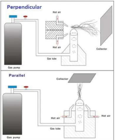
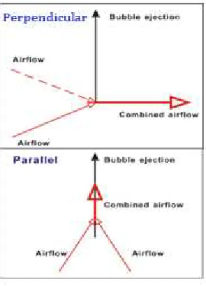
The experimental set-up of the blown bubble-spinning was illustrated in Figure 1. Briefly speaking, com-pressed gas is released inside the spinning solution generating one bubble of the solution at a constant flow. The single bubble is rising along the tube and formed on the free surface of the orifice. At the same time, the blowing hot air in the form of two streams in the shape of a V-slot pulls the bubble upwards rapidly and con-tinuously, and then superfine fibers are obtained on the collector. The process is continued until the polymer bubble in the tank could not be formed. The diameter of orifice is 5.5 millimeter and the die-to-collector distance is constant as 15cm. Temperature and airflow speed adopted in this experiment are 180℃and 500L/min, respectively. The difference of these two setups is the direction between initial velocities of bu b-ble ejection and that of airflow as shown in Figure 2; one is oriented parallel to the direction of airflow while the other is perpendicular, noted as P and V respectively.
Figure 1: The schematic of the experimental set-up of two airflow directions: (top): perpendicular flow; (down): parallel
347 Figure 2:The schematic diagram of direction difference between airflow speed and initial velocities of bubble ejection: (top): Perpendicular; (down): Parallel.
2.3 SCANNING ELECTRON MICROSCOPY
The morphology of electrospun SF nanofibers was observed using an SEM (Hitachi S-4800, Japan) at 20℃, 60 RH. Samples were mounted on a copper plate and sputter-coated with gold layer 20−30 nm thick prior to imaging. The diameters of the fibers were measured from randomly collected SEM images using the Image J software and expressed as mean±standard deviation (SD).
3. RESULTS
In all blown spinning methods, aerodynamic drag force from airflow fields plays a significant role in the formation of fibers. Figure 3 provides the information about morphologies of superfine fibers under different airflow directions. When the direction of airflow is perpendicular to the path of polymer bubble, the fiber attenuation occurred in a complex situation with the change of time and space, which leads to a random array structure similar to that of electrospunnanofibers (Figure 3 left) [29]. However, the direction consistency between airflow and bubble ejection caused fiber mass to concentrate in fiber bundles. Due to the high cen-terline air velocities from the dual airflow (Figure 3 right), the individual superfine fibers were bundled to-gether rather than distributed over a large area.
Figure 3:SEM images of the blown bubble-spun superfine fibers from 10% regenerated SF/FA solutions under different airflow directions, (left): perpendicular, (right): parallel.
348 with the fibers of parallel airflow (1125.00±299.68nm), due to increased air turbulence (Figure 2 up). On the one side, bubble jets are divergently accelerated and stretched under relatively uniform elongational forces in parallel direction; the fiber-to-fiber contacts may easily be formed in the complex interactions from the axial component of the airflow velocity at the centerline which in turn results in the wider fiber distribution. And higher airflow rates from two streams that shape a V-slot (Figure 2 down) reduced the time allowed for di-ameter attenuation [30].
4. CONCLUSIONS
Blown bubble-spinning of regenerated SF ultrafine fibers was carried out at two airflow directions for the first time. It is clear that air flow directions influence not only the morphologies and sizes but also the ar-rangement of final fibers. Random oriented nanofibers with average diameter 524.25±142.41nm were ob-tained when the airflow direction is perpendicular to the path of bubble ejection. Fiber bundles with good orientation were formed when the airflow direction is parallel to the initial velocity of bubble ejection. This study provides a novel method to control the structure and uniformity of superfine fibers by adjusting the airflow direction, which may enhance the properties of end products and broaden the potential applications.
5. ACKNOWLEDGEMENT
The work is supported by Priority Academic Program Development of Jiangsu Higher Education Institutions (PAPD), National Natural Science Foundation of China under grant Nos.11372205&51463021 and Project for Six Kinds of Top Talents in Jiangsu Province under grant No.ZBZZ-035, Science & Technology Pillar Program of Jiangsu Province under grant No.BE2013072, Research and Innovation Project for College Graduates of Jiangsu Province under grant No.CXZZ13-0817, Jiangsu Province Key Laboratory No.KJS1314 and Jiangsu Planned Projects for Postdoctoral Research Funds1401076B.
6. BIBLIOGRAPHY
[1] NANDANA, B., SUBHAS, C. K., “Electrospinning: A Fascinating Fiber Fabrication Technique”, Bio-technology Advances, v.28, n.3, pp. 325-347, 2010.
[2] XU, L., SI, N., LEE, E.W.M., et al., “A multi-phase flow model for electrospinning process”, Thermal Science, V. 17, n. 5, pp. 1299-1304, 2013
[3] WANG, X., et al., “An Improved Tip-less Electrospinning with Strip-distributed Solution Delivery for Massive Production of Uniform Polymer Nanofibers”, Materials Letters, v.99, n.15, pp. 21-23, 2013. [4]LI, H.B., KONG,H.Y., et al., “Particle-like beads and daughter jet cascades in electrospinning”, Thermal Science, v. 17, n. 5, pp. 1421-1424, 2013
[5] CHEN, R.X., ZHANF,L., et al., “Mechanism of nanofiber crimp”, Thermal Science, v. 17, n. 5, pp. 1473-1477, 2013
[6] SINHA-RAY, S.,et al., “Supersonic Nanoblowing: A New Ultra-Stiff Phase of Nylon 6 in 20–50 nm Confinement”, Journal of Materials Chemistry C, v.1, n.21, pp. 3491–3498, 2013.
[7] BENAVIDES, R. E.,et al., “Role of Liquid Jet Stretching and Bending Instability in Nanofiber Formation by Gas Jet Method”, Macromolecules, v.46, n.15, pp. 6081−6090, 2013.
[8] ZUSSMAN, E., et al., “Tensile Deformation of Electrospun Nylon-6,6 Nanofibers”, Journal of Polymer Science: Part B: Polymer Physics, v.44, n.10, pp. 1482-1489, 2006.
[9] PANG, J., KONG, H.Y., et al., “PVA-based nanographene film by electrospinning”, Thermal Science, v. 17, n. 5, pp. 1449-1452, 2013
[10] ZHANG, S., et al., “Design of Ultra-Fine Nonwovens via Electrospinning of Nylon 6: Spinning Parame-ters and Filtration Efficiency”, Materials and Design, v.30, n.9, pp. 3659-3666, 2009.
[11] BARHATE, R. S., RAMAKRISHNA, S., “Nanofibrous Filtering Media: Filtration Problems and Solu-tions from Tiny Materials”, Journal of Membrane Science, v.296, n.1, pp.1–8, 2007.
[12] FENG, C., et al., “Recent Progress in the Preparation, Characterization, and Applications of Nanofibers and Nanofiber Membranes via Electrospinning/Interfacial Polymeriation”, Journal of Applied Polymer Sci-ence, v.115, n.2, pp. 756-776, 2010.
349 [14] KRUCINSKA, I., et al., “Application of Melt-Blown Technology for the Manufacture of Temperature-Sensitive Nonwoven Fabrics Composed of Polymer Blends PP/PCL Loaded with Multiwall Carbon Nano-tubes”, Journal of Applied Polymer Science, v.127, n.2, pp. 869-878, 2013.
[15] RYU, Y. J., et al., “Transport Properties of Electrospun Nylon 6 Nonwoven Mats”, European Polymer Journal, v.39, n.9, pp. 1883-1889, 2003.
[16] TAN, D. H., et al., “Meltblown Fibers: Influence of Viscosity and Elasticity on Diameter Distribution”, Journal of Non-Newtonian Fluid Mechanics, v.165, n.15, pp. 892-900, 2010.
[17] HE,J.H., KONG,H.Y., et al. “Variationaliterationmethod for Bratu-like equation arising in electrospin-ning”, Carbohydrate polymer, v.105,pp.229-230, 2014
[18] YANG, R. R., et al., “Bubble-electrospinning for Fabricating Nanofibers”, Polymer, v.50, n.24, pp. 5846-5850, 2009.
[19] HE, J. H., et al., “Review on Fiber Morphology Obtained by Bubble Electrospinning and Blown Bubble Spinning”, Thermal science, v.16, n.5, pp. 1263-1279, 2012.
[20] HE, J. H., “Effect on Temperature on Surface Tension of A Bubble and Hierarchical Ruptured Bubbles for Nanofiber Fabrication”, Thermal Science, v.16, n.1, pp. 327-330, 2012.
[21] REN, Z. F., HE, J. H., “Single Polymeric Bubble for the Preparation of Multiple Micro/Nano Fibers”, Journal of Applied Polymer Science, v.119, n.2, pp. 1161–1165, 2011.
[22] HE, J. H., LIU, Y.,“Control of Bubble Size and Bubble Number in Bubble Electrospinning”, Computers & Mathematics with Applications, v.64, n.5, pp. 1033–1035, 2012.
[23] LIU, Y., et al., “Effect of Applied Voltage on Diameter and Morphology of Ultrafine Fibers in Bubble Electrospinning”, Journal of Applied Polymer Science, v.120, n.1, pp. 592-598, 2011.
[24] YANG, R. R., et al., “Effect of Solution Concentration on Diameter and Morphology of PVA Nano-fibres in Bubble Electrospinning Process”, Materials Science and Technology, v.26, n.11, pp. 1313-1316, 2010.
[25] LIU, Y., et al., “Bubble Electrospinning Method for preparation of Aligned Nanofibre Mat”, Materials Science and Technology, v.26, n.11, pp. 1309-1312, 2010.
[26] YANG, R. R., et al., “Bubble-electrospinning for Fabrication of Nanofibers with Diameter of about 20nm”, International Journal of Nonlinear Sciences and Numerical Simulation, v.11, pp. 163–164, 2010. [27] DOU, H., LIU, H.Y., et al. “A belt-like superfine film fabricated by bubble-electrospinning”, Thermal Science, v. 17, n. 5, pp. 1508-1510, 2013
[28]DOU,H., LIU, H.Y., MO,L.F., “Blown bubble-spinning and micro yarns”, Bubbfil Nanotechnology, v. 1, n.1, pp.24-28, 2014
[29] BRESEE, R. R., QURESHI, U.A., “Influence of Process Conditions on Melt Blown Web Structure. Part IV - Fiber Diameter”, Journal of Engineered Fibers and Fabrics, v.1, n.1, pp. 32-46, 2006.