*e-mail: [email protected]
Nanocomposites: Synthesis, Structure,
Properties and New Application Opportunities
Pedro Henrique Cury Camargo, Kestur Gundappa Satyanarayana*, Fernando Wypych
Departamento de Química, Centro Politécnico, Universidade Federal do Paraná,
Jardim das Américas, 81531-990 Curitiba - PR, Brazil
Received: November 24, 2008; Revised: February 10, 2009
Nanocomposites, a high performance material exhibit unusual property combinations and unique design possibilities. With an estimated annual growth rate of about 25% and fastest demand to be in engineering plastics and elastomers, their potential is so striking that they are useful in several areas ranging from packaging to biomedical applications. In this uniied overview the three types of matrix nanocomposites are presented underlining the need for these materials, their processing methods and some recent results on structure, properties and potential applications, perspectives including need for such materials in future space mission and other interesting applications together with market and safety aspects. Possible uses of natural materials such as clay based minerals, chrysotile and lignocellulosic ibers are highlighted. Being environmentally friendly, applications of nanocomposites offer new technology and business opportunities for several sectors of the aerospace, automotive, electronics and biotechnology industries.
Keywords: composites, layered compounds, polymers, metals, ceramics
1. Introduction
Nanocomposites are composites in which at least one of the phases shows dimensions in the nanometre range (1 nm = 10–9 m)1.
Nanocomposite materials have emerged as suitable alternatives to overcome limitations of microcomposites and monolithics, while posing preparation challenges related to the control of elemental composition and stoichiometry in the nanocluster phase. They are reported to be the materials of 21st century in the view of possessing design uniqueness and
property combinations that are not found in conventional composites. The general understanding of these properties is yet to be reached2, even
though the irst inference on them was reported as early as 19923.
The number of published papers containing words such as nano-science, nanotechnology, nanomaterials, etc., doubled in 1.6 years4 in
the late 1990s. Also, a literature survey made by the authors reveals that about 13.420 papers (of which 4028 contain the keywords nano-composite and polymer in Web of Science-ISI: updated on 10 February 2009) have been published on nanocomposites in the last two decade (1988-2008). Similarly, patents with complete document on nanocom-posites account for about 4663 during the same period as per Scirus (www.scirus.com). Additionally, speciic conferences and special issues of some journals have been devoted exclusively to the emerging science and technology of nanomaterials.
It has been reported that changes in particle properties can be ob-served when the particle size is less than a particular level, called ‘the critical size’ (Table 1)5. Additionally, as dimensions reach the nanometre
level, interactions at phase interfaces become largely improved, and this is important to enhance materials properties. In this context, the surface area/volume ratio of reinforcement materials employed in the preparation of nanocomposites is crucial to the understanding of their structure–property relationships. Further, discovery of carbon nanotubes (CNTs) in 19916 and their subsequent use to fabricate composites
exhibiting some of the unique CNT related mechanical, thermal and electrical properties7-9 added a new and interesting dimension to this
area. The possibility of spinning CNTs into composite products and textiles10 made further inroads for the processing and applications of
CNT-containing nanomaterials. Nowadays, nanocomposites offer new
technology and business opportunities for all sectors of industry, in addition to being environmentally friendly11.
As in the case of microcomposites, nanocomposite materials can be classiied, according to their matrix materials, in three different categories as shown in Table 2.
Ceramic Matrix Nanocomposites (CMNC); Metal Matrix Nanocomposites (MMNC) and Polymer Matrix Nanocomposites (PMNC).
Nanocomposite systems, including those reinforced with CNTs, have been extensively studied since the 1990s and, accordingly, there has been a steady and continuous increase in the number of publica-tions on the subject, including reviews from time to time2,12-35. In spite
of this growth, the majority of the reviews describe the current status of only one type of nanocomposite. Thus, there are only two reviews on CMNC16,32 and three on CNT-reinforced nanocomposites17,20,27 and a
quite large number on PMNC16,18,19,21,28-35. In the case of PMNC, reviews
deal with processing aspects, including those on layered silicates18,26,
conducting and biodegradable polymer-based systems19,34,35, ibre
reinforced17,20 and structure/morphology/property aspects16,35, as well
as with applications and perspectives, including key opportunities and challenges in the development of structural and functional ibre nanocomposites18,26,29.
Conducting polymer-based composites are novel materials with less than a decade of history. It is believed19 that the total control of the
whole conducting polymer-based composite system and the optimisa-tion of their physical properties (such as electrical conductivity and colloidal stability) are yet to be achieved, while both their commercial availability in the near future and a big leap forward for materials science are expected with their appropriate utilization. In the case of biodegradable polymer-based nanocomposites, recent developments in preparation, characterization and properties, including crystalliza-tion behaviour and melt rheology, of both the matrix and the layered (montmorillonite) nanocomposites have been discussed34,35. Similarly,
from the matrix and the potential of these composites for possible macro scale CNT-polymer production. Here, problems encountered so far are considered, and hints given regarding a critical volume fraction of CNTs to get appropriate strengthening (as observed in microcomposites); possible failure mechanisms in such composites are also presented. Finally, to the best of our knowledge, and in view of the very limited work on metal-based nanocomposites including the ones with CNT reinforcements, no review is available to-date on this system.
Considering these facts and also the absence of a more general review comprising the three different kinds of nanocomposites (metal-, ceramic- and polymer-based), this paper gives an overview of them, including those with incorporation of CNTs. However, while doing so only a few relevant publications2,4,7-9,11,14-308 are considered here. The
main features, current status and recent developments in the area are provided, focussing on the preparation methods, structure, properties and applications of these systems to avoid repetition. Also, the poten-tial uses of nanocomposites and the opportunities they provide, along with perspectives for the future and market and safety aspects are also presented. Nanocomposite coating is not covered, in order to keep the focus of the review.
1.1. Potentials and opportunities in nanocomposites
Before going into details regarding processing, structure, properties and applications of the three types of nanocomposites, let us look at the potentials of these systems and the general opportunities they provide. Ceramics have good wear resistance and high thermal and chemical stability. However, they are brittle. In this context, the low toughness of ceramics has remained a stumbling block for their wider use in industry. In order to overcome this limitation, ceramic-matrix nanocomposites have been receiving attention, primarily due to the signiicant enhance-ment on mechanical properties which can be achieved. For example, the incorporation of energy-dissipating components such as whiskers, ibres, platelets or particles in the ceramic matrix may lead to increased fracture toughness309-311. The reinforcements delect the crack and/or
provide bridging elements, hindering further opening of the crack. In
addition, the incorporated phase undergoes phase transition in con-junction with the volume expansion initiated by the stress ield of a propagating crack, contributing for the toughening and strengthening processes, even in nanocomposites36.
The potential of ceramic matrix nanocomposites (CMNC), mainly the Al2O3/SiC system, was revealed by the pioneering work of Niihara37,38. Most studies reported so far have conirmed the noticeable
strengthening of the Al2O3 matrix after addition of a low (i.e. ~10%) volume fraction of SiC particles of suitable size and hot pressing of the resulting mixture. Some studies have explained this toughening mecha-nism based on the crack-bridging role of the nanosized reinforcements39.
Consequently, the incorporation of high strength nanoibres into ceramic matrices has allowed the preparation of advanced nanocomposites with high toughness and superior failure characteristics compared to the sudden failures of ceramic materials40.
Metal matrix nanocomposites (MMNC) refer to materials consist-ing of a ductile metal or alloy matrix in which some nanosized rein-forcement material is implanted. These materials combine metal and ceramic features, i.e., ductility and toughness with high strength and modulus. Thus, metal matrix nanocomposites are suitable for produc-tion of materials with high strength in shear/compression processes and high service temperature capabilities. They show an extraordinary potential for application in many areas, such as aerospace and automo-tive industries and development of structural materials41. Both MMNC
and CMNC with CNT nanocomposites hold promise, but also pose challenges for real success.
Polymer materials are widely used in industry due to their ease of production, lightweight and often ductile nature. However, they have some disadvantages, such as low modulus and strength compared to metals and ceramics. In this context, a very effective approach to improve mechanical properties is to add ibres, whiskers, platelets or particles as reinforcements to the polymer matrix. For example, polymers have been illed with several inorganic compounds, either synthetic or natural, in order to increase heat and impact resistance, lame retardancy and mechanical strength, and to decrease electrical conductivity and gas permeability with respect to oxygen and water vapour25. Furthermore, metal and ceramic reinforcements offer
strik-ing routes to certain unique magnetic, electronic, optical or catalytic properties coming from inorganic nanoparticles, which add to other polymer properties such as processibility and ilm forming capability42.
Using this approach, polymers can be improved while keeping their lightweight and ductile nature31,43-47. Another important aspect is that
nanoscale reinforcements have an exceptional potential to generate new phenomena, which leads to special properties in these materials as will be seen later. It may be pointed out that the reinforcing eficiency of these composites, even at low volume fractions, is comparable to 40-50% for ibres in microcomposites34.
Addition of reinforcements to a wide variety of polymer resins produces a dramatic improvement in their biodegradability. This un-derlines a good example of polymer matrix nanocomposites [PMNC] as promising systems24 for ecofriendly applications. Besides, future
space mission concepts involve large ultra lightweight spacecrafts termed “Gossamer”48. The materials required for such spacecrafts
should possess and maintain a speciic combination of properties for over a long period (10-30 years) in relatively harsh environments such as 173 to 373 K for satellites and cycling temperatures of 1273 K for re-entry vehicles, exposure to atomic O2 and solar radiation. Some of the Gossamer spacecraft devices are movable mechanical parts such as gears and gyroscopes, and others include solar arrays/sails, antennae and drives, sunshields, rovers, radars, solar concentrators, and relector arrays. It is reported48 that these parts will have to be fabricated from
lexible, appropriate materials, which can be folded or packaged into small volumes, similarly to those available in conventional launch ve-hicles, and should possess many of the common mission concepts. This is needed since the structure consisting of ultra lightweight parts would
Table 1. Feature sizes for signiicant changes in properties reported in na-nocomposite systems [reproduced from reference 5 with the kind permission of the author and the Japan Society of Powder and Powder Metallurgy].
Properties Feature size (nm) at
which changes might be expected
Catalytic activity <5
Making hard magnetic materials soft <20
Producing refractive index changes <50
Producing super paramagnetism and others electromagnetic phenomena
<100
Producing strengthening and toughening <100
Modifying hardness and plasticity <100
Table 2. Different types of nanocomposites.
Class Examples
Metal Fe-Cr/Al2O3, Ni/Al2O3, Co/Cr, Fe/MgO, Al/CNT, Mg/CNT
Ceramic Al2O3/SiO2, SiO2/Ni, Al2O3/TiO2, Al2O3/SiC, Al2O3/CNT
Polymer Thermoplastic/thermoset polymer/layered
be deployed mechanically or by inlation into a large ultra-lightweight functioning spacecraft once it achieves the required orbit. It is impera-tive that the above mentioned characteristics should be available in one single material. Metal oxide-incorporated polymer nanocomposites seem to meet these requirements. It is expected that such spacecrafts offer a signiicant cost advantage compared to on-orbit construction, and the large size can enable some unique missions. Similarly, rocket propellants are prepared from a polymer-Al/Al2O3 nanocomposite to improve ballistic performance306. In addition, recent information on
nanomaterials, nanoindustries and a host of possible A to Z applications of polymer nanocomposites have been reported312.
On the other hand, even after a decade of research27, CNTs have
not fully realized their potentials as nanoscopic reinforcements313-334
in polymer matrices. Thus great challenges and opportunities are still expected for the system. These are based on the following:
a) CNTs with small number of defects per unit length possess27
500 times more surface area per gram on the basis of equivalent volume fraction of a typical carbon iber, high aspect ratio (~1000), very high tensile properties and electrical and thermal conductivities (more details are given in the next section). b) Research on CNT-related areas has been most active, with
publications doubling within six months335. Even the patenting
activity in this area has been impressive, with about 3,000 ap-plications iled from 2001 to June 2006 as per the literature survey.
c) Because of their hollow nature, CNTs can be opened and illed with a variety of materials including biological molecules335,
generating technological opportunities. Added to this, the challenges in obtaining homogeneous dispersions and strong interfacial interactions, which can be better done by surface grafting/functionalizations, make the use of CNTs in compos-ites more intriguing49.
d) Various applications of CNTs in composites have been reported extensively 30,33,313-334.
e) The possibility of spinning polymers to obtain textiles10
certainly constitutes a great promise for their extended use in a variety of applications, particularly in the electronic and thermal management sectors.
f) Nanoreinforcements with biodegradable polymers have a high potential for the design of environmentally friendly ‘green materials’ for future applications.
On the whole, opportunities and rewards appear to be great with nanocomposites and hence there is a tremendous worldwide interest in these materials.
2. Processing of Nanocomposites
2.1. Raw materials
As with microcomposites, CMNC matrix materials include Al2O3, SiC, SiN, etc., while metal matrices employed in MMNC are mainly Al, Mg, Pb, Sn, W and Fe, and a whole range of polymers, e.g. vinyl polymers, condensation polymers, polyoleins, speciality polymers (including a variety of biodegradable molecules) are used in PMNC. In general, it is the reinforcement that is in the nanorange size in these materials. Both synthetic and natural crystalline reinforcements have been used, such as Fe and other metal powders, clays, silica, TiO2 and other metal oxides, although clays and layered silicates are the most common176. This is so due to their availability with very low particle
sizes and well-known intercalation chemistry18,50,51, in addition to
generating improved properties even when they are used at very low concentrations252. Most of these reinforcements are prepared by known
techniques: chemical, mechanical (e.g. ball milling), vapour deposition, etc.; details of these may be found in many of the references given in the following sections.
Similarly, CNTs are prepared mostly by chemical/vapour deposi-tion methods and details are available elsewhere319-327. A bibliometric
analysis of CNTs made in 2000335 revealed that about 49% of the patents
iled between 1992-1999 were related to the processing of CNTs and about 14% to their structure, properties and models. CNTs consist of graphene cylinders and are available in two varieties, as single walled (SWCNT) and multi walled (MWCNT), with about 70% yield in the case of SWCNT317. While SWCNTs are single graphene cylinders,
MWCNTs consist of two or more concentric cylindrical sheets of graphene around a central hollow core. Both types exhibit physical characteristics of solids, either metallic or semiconducting in nature, with microcrystallinity and very high aspect ratios of 103.
Surface modiications of reinforcements are carried out to give homogeneous distribution with less agglomeration, and to improve interfacial bonding between the matrix and the nanosized reinforce-ments. Details on these can be found in the references given for each type of nanocomposites in later Sections. In the case of CNTs, use of surfactants, oxidation or chemical functionalization of surfaces are some of the techniques employed27. Chemical methods may be more
effective, particularly for polymer and ceramic matrices. Physical blending and in situ polymerization are used for improving dispersion in the case of CNT-reinforced polymer composites, while alignment of CNTs could be achieved by techniques such as ex-situ techniques (iltration, template and plasma-enhanced chemical vapour deposition, force ield-inducements, etc.)33.
Table 3a. Processing methods for ceramic nanocomposites.
Method System Procedure Ref.
Powder Process Al2O3/SiC i) Selection of raw materials [mostly powders - small average size, uniformity
and high purity]; ii) Mixing by wet ball milling or attrition milling techniques in organic or aqueous media; iii) Drying by heating, using lamps and/or ov-ens, or by freeze-drying; iv) consolidation of the solid material by either hot pressing or gas pressure sintering or slip casting or injection moulding and pressure iltration.
38, 53
Polymer Precursor Process
Al2O3/SiC, SiN/SiC Mixing a Si-polymeric precursor with the matrix material → Pyrolysis of the mixture using a microwave oven, generating the reinforcing particles.
16, 54-57
Sol-Gel Process SiO2/Ni, ZnO/Co, TiO2/
Fe2O3, La2O3/TiO2, Al2O3/ SiC, TiO2/Al2O3, Al2O3/SiO2, Al2O3/SiO2/ ZrO2, TiO2/Fe2 TiO5, NdAlO3/Al2O3
Hydrolysis and polycondensation reactions of an (in)organic molecular pre-cursor dissolved in organic media. Reactions lead to the formation of three-dimensional polymers containing metal-oxygen bonds (sol or gel) → drying to get a solid material and further consolidation by thermal treatment.
2.2. Processing methods
Despite their nano dimensions, most of the processing techniques of the three types of nanocomposites remain almost the same as in microcomposites. This is also true even for CNT-reinforced composites. Details on these techniques are given below.
2.2.1. Ceramic Matrix Nanocomposites (CMNC)
Many methods have been described for the preparation of ceramic matrix nanocomposites 20,38,53-112. The most common methodologies, as
used for microcomposites, are Conventional powder method; Polymer precursor route; Spray pyrolysis; Vapour techniques (CVD and PVD)
and Chemical methods, which include the sol-gel process, colloidal and precipitation approaches and the template synthesis. While Table 3a lists systems prepared by some of these methods, Table 3b shows their advantages and limitations. Scheme 1a depicts the conventional powder method and Scheme 1b illustrates the polymer precursor route used in the synthesis of an Al2O3/SiC nanocomposite.
A large variety of parameters affecting the sol-gel process, such as type of solvent, timing, pH, precursor, water/metal ratio, etc., al-low a versatile control of structural and chemical properties of the inal oxide materials61. Regarding the processing of carbon nanotubes
(CNT)-reinforced ceramic nanocomposites, many approaches have been described20,74-112. Several of these are listed in Table 3c.
Table 3b. Advantages and limitations of ceramic nanocomposite processing methods.
Method Advantages Limitations Ref.
Powder Process Simple Low formation rate, high temperature,
ag-glomeration, poor phase dispersion, formation of secondary phases in the product.
38, 53
Polymer Precursor Process
Possibility of preparing iner particles; better reinforcement disper-sion
Inhomogeneous and phase-segregated mate-rials due to agglomeration and dispersion of ultra-ine particles
16, 54-57
Sol-Gel Process Simple, low processing temperature; versatile; high chemical ho-mogeneity; rigorous stoichiometry control; high purity products; formation of three dimensional polymers containing metal-oxygen bonds. Single or multiple matrices. Applicable speciically for the production of composite materials with liquids or with viscous luids that are derived from alkoxides.
Greater shrinkage and lower amount of voids,
compared to the mixing method. 58-73
Table 3c. Processing methods for ceramic-CNT nanocomposites.
Process System Procedure Ref.
Hot pressing SiO2/CNT,
SiC/CNT
Dispersion of CNTs and SiO2 glass powders into ethanol, stirring and ultrasonic treatment, drying and hot pressure sintering in pure N2 atmosphere. Mixing of nanoparticles of SiC and carbon nanotubes
20, 74
CVD or Spray pyrolysis Al2O3/CNT Preparation of the alumina matrix by anodizing growth of CNTs into its porous walls. CNTs grow into hexagonal array of straight pores extending from the substrate to the matrix surface.
75, 77
Catalytic decomposition Al2O3/CNT Use of acetylene over Al2O3 powder impregnated with iron catalysts. 76
Solvothermal process Fe3O4/CNT Dispersion of CNTs in EDA (ethylenediamine) using ultrasonic treatment; addition of an iron(III)-urea complex; heating in a Telon-lined autoclave maintained at 200 °C for 50 hours, followed by cooling to room temperature.
78
α-Al2O3 + β-SiC
Ultrasonic bath
Ball-milling with ZrO2 balls in methanol (48 hours)
Drying under infrared lamp
Hot pressing at 1700 °C under N2
Al2O3/SiC nanocomposite
(a)
α-Al2O3 + polymer (polycarbosilane)
Coated α-Al2O3 powder
Coating/drying
Pyrolysis at 1500 °C: SiC nanoparticles
Hot pressing at 1700 °C
Al2O3/SiC nanocomposite
(b)
2.2.2. Metal Matrix Nanocomposites (MMNC)
The most common techniques for the processing of metal matrix nanocomposites are113-150 Spray pyrolysis; Liquid metal iniltration;
Rapid solidiication; Vapour techniques (PVD, CVD); Electrodeposition and Chemical methods, which include colloidal and sol-gel processes. Table 4a lists various systems prepared by these methods and Table 4b shows their advantages and limitations. Only two reports are found, for example, on Fe-based nanocomposites prepared by solidiica-tion techniques. The irst one, by Branagan121, is called “devitriied
nanocomposite steel”. This was obtained by quenching the metallic glass obtained from a Fe-based alloy, followed by devitrifying the glass precursor through heat treatment above its crystallization tem-perature. This resulted in a material showing a crystalline multi-phase microstructure. The formation of nanophases was explained by the high nucleation frequency within the limited time for growth of grains before impingement. In order to explain the very high hardness of these Fe-based nanocomposites, Branagan and Tang studied122 novel
nanostructures obtained in bulk Fe alloys by designing alloy composi-tions with different amounts of W and C to get maximum solubility. Dificulties have been encountered in preparing composites with very ine particles due to their induced agglomeration and non-homogeneous distribution. Use of ultrasound helped to improve the wettability be-tween the matrix and the particles.
A number of CNT-reinforced MMCs have been synthesised by different techniques87,135-141 since the irst report in 2002137. Some of
these techniques are listed in Table 4c.
2.2.3. Polymer Matrix Nanocomposites (PMNC)
Many methods have been described for the preparation of polymer nanocomposites, including layered materials and those containing CNTs 151-308. The most important ones are i) Intercalation of the polymer
or pre-polymer from solution; ii) In-situ intercalative polymerization; iii) Melt intercalation (Figure 1); iv) Direct mixture of polymer and particulates; v) Template synthesis; vi) In-situ polymerization; and vii) Sol-gel process. Publications dealing with various methods for the incorporation of nanodispersoids into conducting polymers are also available19,201,234; the most prominent one is probably the incorporation
of inorganic building blocks in organic polymers.
Table 5a shows the procedures adopted in some of these processes, while their advantages and limitations are listed in Table 5b.
Intercalative processes employed for the preparation of polymer-based nanocomposites, including those containing layered silicates, are shown in Scheme 2. It may be noted that, in this method, a range of nanocomposites with structures from intercalated to exfoli-ated can be obtained, depending on the degree of penetration of the polymer chains into the silicate galleries. As a result, this procedure has become standard for the preparation of polymer-layered silicate combinations.
The preparation of CNT-reinforced polymer nanocomposites is generally performed by different methods, including direct mixing, solution mixing, melt-mixing and in-situ polymerisation. These, as applicable to various systems187,202, are listed in Table 5c.
Table 4a. Processing methods for metal-based nanocomposite systems.
Process System Procedure Ref.
Spray Pyrolysis Fe/MgO, W/Cu i) Dissolution of the inorganic precursors (starting materials) in a suitable solvent to get the liquid source; ii) Generation of a mist from this liquid source using an ultrasonic atomizer; iii) Use of a carrier gas to carry the mist into a pre-heated chamber. iv) Vaporisation of the droplets in the chamber and trapping with a ilter, promoting their decomposition to give the respective oxide materials; v) Selective reduction of the metal oxides to produce the respec-tive metallic materials.
11
Liquid Iniltration Pb/Cu, Pb/Fe,
W/Cu/ Nb/Cu, Nb/Fe, Al-C60
i) Mixing of ine reinforcement particles with the matrix metal material; ii) Thermal treat-ment, whereby the matrix melts and surrounds the reinforcements by liquid iniltration; iii) Further thermal treatment below the matrix melting point, to promote consolidation and eliminate internal porosity.
11, 114-117
Rapid Solidiication Process(RSP)
Al/Pb, Al/X/Zr (X = Si, Cu, Ni), Fe alloy
i) Melting of the metal components together; ii) Keeping the melt above the critical line of the miscibility gap between the different components to ensure homogeneity; iii) Rapid solidiication of the melt by any process, such as melt spinning.
118-122
RSP with
ultrasonics Al/SiC Use of ultrasonics for mixing and for improving wettability between the matrix and the reinforcements. 123 High Energy
Ball Milling
Cu-Al2O3 Milling the powders together till the required nanosized alloy is obtained → Nanocompos-ite.
124
CVD/PVD Al/Mo, Cu/W,
Cu/Pb PVD: i) Sputtering/evaporation of different components to produce a vapour-phase; ii) Supersaturation of the vapour phase in an inert atmosphere to promote the condensation of metal nanoparticles; iii) Consolidation of the nanocomposite by thermal treatment under inert atmosphere.
CVD: Use of chemical reactions to get vapours of materials, followed by consolidation.
125-129
Chemical Processes (Sol-gel, Colloidal)
Ag/Au, Fe/SiO2, Au/Fe/Au
Colloidal Method: i) Chemical reduction of inorganic salts in solution to synthesize metal particles; ii) Consolidation of the dry material; iii) Drying and thermal treatment of the result-ing solid in reducresult-ing atmosphere, such as H2, in order to promote selective oxide reduction and generate the metal component.
Sol-gel process: i) Preparation of two micelle solutions using mesoporous silica containing 0.1 M HAuCl4 (aq.) and 0.6 M NaBH4 (aq.); ii) Mixing under ultraviolet light till complete reduction of the gold.
For Fe/Au-containing nanocomposites: i) Synthesis of the iron shell; ii) Preparation of the second shell and drying of the powders after second gold coating; iii) Pressing of the mixture to get the inal material..
Similarly, different processing techniques, mostly chemical and electrochemical methods, have been employed for the preparation of conducting polymer nanocomposites19. Table 6a summarizes these
methods, while a relevant categorization of these nanocomposites is presented in Table 6b.
In the case of nanocomposites containing layered reinforcements, depending on the nature of the components (layered silicate, organic cation and polymer matrix), the method of preparation and the strength of interfacial interactions between the polymer matrix and the layered silicate (modiied or not), three different types of PLS nanocomposites may be obtained, as illustrated in Figure 218.
When the polymer is unable to intercalate between the silicate sheets, a phase-separated composite (Figure 2) is obtained, whose properties stay in the same range as that of traditional microcomposites. On the other hand, in intercalated nanocomposites, the insertion of a polymer matrix into the layered silicate structure occurs in a crystal-lographically regular fashion, regardless of the clay to polymer ratio. A well ordered multilayer morphology built up with alternating polymeric and inorganic layers is generated. Normally, only a few molecular layers of polymer can be intercalated in these materials.
The in-situ method can be used with mineral/vegetal ibres, with the possibility to attach the polymer to the grafted surface through linking
Table 4b. Advantages and limitations of processing methods for metal-based nanocomposites.
Process Advantages Limitations Ref.
Spray Pyrolysis Effective preparation of ultra ine, spherical and
homogeneous powders in multicomponent systems, reproductive size and quality.
High cost associated with producing large quantities
of uniform, nanosized particles. 11
Liquid Iniltration Short contact times between matrix and
reinforce-ments; moulding into different and near net shapes of different stiffness and enhanced wear resistance; rapid solidiication; both lab scale and industrial scale production.
Use of high temperature; segregation of reinforce-ments; formation of undesired products during processing.
11, 114-117
Rapid Solidiication
Process (RSP) Simple; effective. Only metal-metal nanocomposites; induced ag-glomeration and non-homogeneous distribution of ine particles.
118-122
RSP with ultrasonics Good distribution without agglomeration, even with
ine particles.
123
High Energy Ball Milling
Homogeneous mixing and uniform distribution. 124
CVD/PVD Capability to produce highly dense and pure
materi-als; uniform thick ilms; adhesion at high deposition rates; good reproducibility.
Optimization of many parameters; cost; relative complexity.
125-129
Chemical Processes (Sol-Gel, Colloidal)
Simple; low processing temperature; versatile; high chemical homogeneity; rigorous stoichiometry control; high purity products.
Weak bonding, low wear-resistance, high permeability and dificult control of porosity.
130-134
Table 4c. Processes for preparing metal-CNT nanocomposite systems.
Process System Procedure Ref.
Electroless Coating
Co-CNT i) Use of electroless plating bath containing the activated CNTs, the cobalt precursor, the reducing
agent CoSO4.7H2O, the complexing agent and a buffer. CNT with deposit of Co coating results; ii) Thermal treatment at 873 K, 200 torr, under a 10% H2/N2 low gas.
135
Electroless Coating
Sn / CNTs, SnSb0.5/ CNT and Sn2Sb/ CNT
Reduction of SnCl2 and SbCl3 precursors by KBH4 in the presence of CNTs. 136,
137
Hot Pressing Al/CNT Mixing of powders through grinding for 30 minutes and hot pressing at 793 K under a pressure
of 25 MPa.
138
Nanoscale Dispersion
Al/CNT Preparation of the precursor of MWCNT (13 nm dia and 10-50 µm long) with natural rubber and
ethyl propylene; mixing with Al powder; rolling into sheets by compression moulding at 353 K; placing of this precursor on an Al (99.85%) plate of 28 µm grain size; heating to 1073 K in N2 atmosphere for one hour; inal cooling.
139
PM/Iniltration Mg-Al2O3f-CNT a) Mechanical mixing of Mg powders with MWCNT (1 vol. %) using alcohol and acid;
sinterisa-tion at 550 °C under 25 MPa pressure;
b) Iniltration of molten Mg through performs of Al2O3 ibers (25 vol. %; 40-100 µm long) covered with MWCNTs under gas pressure.
141
+
Intermolecular interactionsSilicate layer Polymer Aliphatic chains Heat
Table 5a. Processing methods for polymer-based nanocomposite systems.
Process System Procedure Ref.
Intercalation / Prepolymer from Solution
Clay with PCL, PLA, HDPE, PEO, PVA, PVP, PVA, etc.
Employed for layered reinforcing material in which the polymer may intercalate. Mostly for layered silicates, with intercalation of the polymer or pre-polymer from solution. Use of a solvent in which the polymer or pre-polymer is soluble and the silicate layers are swellable.
5, 18,
151-157
In-situ Intercalative Polymerization
Montmorillonate with N6/PCL/ PMMA /PU/Epoxy
Encasing of the layered silicate within the liquid monomer or a mono-mer solution → formation of polymer between the intercalated sheets. Polymerization by heat or radiation, by diffusion of a suitable initiator or by a catalyst ixed through cation exchange inside the interlayer, before the swelling step.
158-164
Melt Intercalation Montmorillonate with PS/PEO/PP/
PVP, Clay-PVPH
Annealing of a mixture of the polymer and the layered host above the softening point of the polymer, statically or under shear. Diffusion of polymer chains from the bulk polymer melt into the galleries between the host layers during annealing (Figure 1).
165-169
Template Synthesis Hectorite with PVPR, HPMC,
PAN, PDDA, PANI
In situ formation of the layered structure of the inorganic material in an aqueous solution containing the polymer. The water soluble polymer acts as a template for the formation of layers. Widely used for the synthesis of LDH nanocomposites, but less developed for layered silicates.
170-175
(a) Mixing (b) In situ polymerization
PVA)/Ag; PMMA/Pd Polyester/ TiO2
PET/CaCO3, Epoxy vinyl ester/ Fe3O4 ; Epoxy vinyl ester/γ-Fe2O3; Poly (acrylic acid)(PAA)/Ag, PAA/ Ni and PAA/Cu
AgNO3, NiSO4 and CuSO4;
(a) Mixing of either polymer or monomer with reinforcing materials; (b1) Dispersion of inorganic particles into a precursor of the polymeric matrix (monomer); (b2) Polymerization of the mixture by addition of an appropriate catalyst;
(b3) Processing of this material by conventional moulding technolo-gies.
Use of ultrasonics for dispersion in epoxy systems. Exposition of AG systems to 60 Co γ-ray to promote simultaneous polymerization and metal nanoparticle formation.
178-183
Sol-Gel Process Polyimide/SiO2; 2-hydroxyethyl
acrylate (HEA)/SiO2, polyimide/ silica. PMMA/ SiO2, polyethylacr-ylate/ SiO2, polycarbonate / SiO2 and poly (amide-imide)/TiO2
Embedding of organic molecules and monomers on sol-gel matrices; introduction of organic groups by formation of chemical bonds → In-situ formation of sol-gel matrix within the polymer and/or simultaneous generation of inorganic /organic networks.
24, 184-186
Table 5b. Advantages and limitations of polymer-based nanocomposite processing methods.
Process Advantages Limitations Ref.
Intercalation / Prepolymer from Solution
Synthesis of intercalated nanocomposites based on polymers with low or even no polarity. Prepa-ration of homogeneous dispersions of the iller.
Industrial use of large amounts of solvents. 5, 18,
151-157
In-situ Intercalative
Polymerization Easy procedure, based on the dispersion of the iller in the polymer precursors. Dificult control of intragallery polymerization. Limited applications. 158-164
Melt Intercalation Environmentally benign; use of polymers not
suited for other processes; compatible with in-dustrial polymer processes.
Limited applications to polyoleins, who represent the majority of used polymers.
165-169
Template Synthesis Large scale production; easy procedure. Limited applications; based mainly in water soluble
polymers, contaminated by side products.
170-175
Sol-Gel Process See Table 3b. See Table 3b.
Table 5c. Processing methods for polymer-CNT nanocomposite systems.
Process System Procedure Remarks Ref.
Direct Mixing Thermoset Resins Dispersion of CNTs; Cure. 187
Solution Mixing Thermoplastic Resins
(PS/Epoxy)
Dispersion of 0.2-1% CNTs, (100 nm dia, 10 µm long); Removal of solvent or precipitation of polymer; Cure.
Modiication of polymer behaviour; synergistic effect; shape memory nanocomposites.
188-193
Melt Mixing Polymers, N6 Mechanical mixing of CNTs with
pre-polymer melt followed by extrusion, injection or compression moulding.
Use of 0.2-2.0% MWCNT, twin screw mixer.
49, 194, 195
In-situ Polymerization Polyaniline-CNT, MMA-CNT, Epoxy-CNT, Poly(ether-ester)
Use of ultrasonics for dispersion in
monomer/matrix; Cure. Preparation of the polymer with CNT, good chemical bonding. 196-202
Others PP-CNT, PVK-SWCNT,
iPP-SWCNT, PANi-SWCNT
Solid-state mechanochemical pulveriza-tion; blending + sonicapulveriza-tion; melt blend-ing; VDP.
groups (coupling agents), which optimize the interface bonding and, consequently, the mechanical properties176.
Despite the successful use of these different methods for the preparation of polymer-based nanocomposites, information on
vari-ous factors is still lacking, such as i) the use of an appropriate method for a speciic matrix-reinforcement combination or ii) the maximum amount of reinforcements to give optimum property combinations and lower the cost of the processes, etc. Therefore, it is still necessary
Table 6a. Summary of processing methods for conducting polymer nanocomposites [reproduced from ref. 19 with the permission of the authors and the American Chemical Society, USA]
Polymer of interest (Shell)
Inorganic particle (core) Signiicant characterization / Applications
PPy and PAn SiO2 (1 µm, 35 nm, 20 nm), SnO2
-Sb(10 nm), Stringy SiO2 (40-300 nm long)
Stable colloidal form, ‘raspberry morphology’ and inorganic stable rich surface.
PPy and PAn CeO2 (0.52 µm), CuO (1.6 µm),
α-Fe2O3 (Sph, Polyhedral and spindle shaped), NiO (3.8 µm), SiO2 (0.46 µm)
Colloidally stable nanocomposite with low dc conductivity and formed without a polymerisation initiator.
PPy and PAn BaSO4(20 nm), Colloidal gold
(7-9 nm), Al2O3 membrane
In situ formation of colloidal nanocomposite within the microemulsion or inside the Al2O3 membrane.
Ppy, Pan, NVC and PPV ZrO2 (20-30 nm), Fe2O3 (25-50 nm), SiO2, n-TiO2 (~10 nm), Al2O3 (35-40 nm), MgO (2-4 µm), CB
Nanocomposites in macroscopic precipitate form or with limited colloidal stability but improved thermal and electrical properties and novel transport properties.
PPy and PAOABSA MS (15-30 nm), FexOy (14 nm),
Fe2O3 (~15-50 nm), γ-Fe2O3 (85 nm),
Nanocomposites with signiicant magnetic susceptibility.
PPy and PAn BT (~1 µm), LiMnO2, LiMnO4,
V2O5, β-MnO2, PMo12, H3PMo12O40, CB, Fe2O3 (4 nm, 40 nm)
Nanocomposites with important charge storage and dielectric properties, suitable for cathode applications.
Ppy, Pan, PTh and PEDOT Pt (~4 nm), PtO2, Pt, Cu, Pd, SiO2 (20 nm), & bimetallic couples
Nanocomposites with catalytically important metals; catalytic applica-tions.
PPy and PAn SiO2 (20 nm) Grafted surface nanocomposites - important for immunodiagnostic assays.
PPy SiO2, PB, MnO2, Ta2O5, TiO2 Electrochemically synthesised composite ilms with improved charge
stor-age properties.
PPy and PAn WO3 Nanocomposite ilms with important ECD application and optical activity.
Table 6b. Categorization of processing methods for conducting polymer nanocomposites [reproduced from reference 19 with the permission of the authors and the American Chemical Society, USA].
Conducting polymer nanocomposites
Inorganic-in-organic Organic-in-inorganic
Chemical preparation Electrochemical preparation
Nanocomposites with colloidal stability (SiO2, SnO2, BaSO4, etc., as core)
Nanocomposites with charge storage, optical and electrochromic activities (incorporation of MnO2, SnO2, CB, PB, WO3, SiO2, etc.)
Nanocomposites with improved physical and mechanical properties (Fe2O3, ZrO2, TiO2, etc., as incorporated materials)
Nanocomposites with catalytic activities (incorporation of catalytically active Pt, Pd, Cu, etc. microparticles and some bimetallic couples like Pd/Cu, etc.)
Nanocomposites with magnetic susceptibility (using Fe2O3, γ-Fe2O3, etc., magnetic particles)
Nanocomposites with magnetic susceptibility (γ-Fe2O3 magnetic macroanion)
Nanocomposites with dielectric, energy storage, piezoresistive and catalytic activities (with BT, POM, PtO2, TiO2, Pd, Pt, etc., incorpora-tion)
-Nanocomposites with grafted surface (NH2/COOH functional groups
-to look in-to these aspects including use of simulation and modelling techniques.
3. Structure and Properties
The structure of nanocomposites usually consists of the matrix mate-rial containing the nanosized reinforcement components in the form of particles, whiskers, ibres, nanotubes, etc.93. Different investigators have
employed various equipments and techniques for the characterization of nanocomposites, including atomic force microscopy (AFM), scanning tunnelling microscopy (STM), Fourier transformed infrared spectroscopy (FTIR), X ray photoelectron spectroscopy (XPS), nuclear magnetic resonance (NMR), differential scanning calorimetry (DSC), scanning and transmission electron microscopy (SEM/TEM), etc. For example, AFM is a powerful tool to study the surface even down to the nanometre scale, as evident from the work of Veith et al.303,304. Simultaneous small angle
X ray scattering (SAXS) and X ray diffractometry (XRD) studies have been recently used for quantitative characterization of nanostructures and crystallite structures in some nanocomposites34,307,308. In addition,
theoretical calculations/simulations have been worked out to predict strength properties, including stress/strain curves41,52,166,169,207-212,290,291.
Before discussing structure and properties of nanocomposites, including those containing CNTs, a brief description of CNTs will be made here313-334, because of their unique properties compared to other
reinforcements. Briely, the density of SWCNTs is less than one sixth of that of steel335 while the density of MWCNT is one half of that of
Al30. Tensile strengths of SWCNT and MWCNTs are reported313-316,335
to be in a range much higher than of high strength steel, while Young’s modulus values are comparable to those of diamond. They exhibit tre-mendous resilience, in that they can sustain bending to large angles and restraightening without damage, in which they differ from the plastic deformation of metals and the brittle fracture of carbon ibres. Similarly, theoretical thermal and electrical conductivities are comparable with that of diamond, with an almost negligible thermal expansion coeficient30.
They also exhibit high thermal stability both in air and in vacuum, com-pared to the lower values obtained for metal wires in microchips, and high parallel and perpendicular magnetic susceptibilities. Theoretical surface area values of these materials are ca. 3,000 m2/g 318-321, while the
experimentally reported values vary depending on the gas used during the measurements. This information is summarized in Table 7.
Layered silicate is first swollen in a solvent such as water, chloroform or toluene
After mixing, the polymer chains intercalated and displace the solvent within the interlayer of the silicate
Upon solvent removal, the intercalated structure remains, resulting in the polymer-layered silicate nanocomposite
Polymer solution
Scheme 2. Intercalation of polymer or pre-polymer from solution.
Layered silicate Polymer
(a) Phase separated (microcomposite)
(b) Intercalated (nanocomposite)
(c) Exfoliated (nanocomposite)
Figure 2. Different types of composites arising from the interaction of layered silicates, polymers: a) Phase-separated microcomposite; b) Intercalated nano-composite, and c) Exfoliated nanocomposite [reproduced from reference 18 with the kind permission of the authors, Elsevier].
Table 7. Properties of Carbon Nanotubes30,313-318,335.
Properties SWNT MWNT Corresponding values in other known materials
Density (Mgm–3) 0.8 1.33-1.40
(Expt.) 1.8 (Theor.)
One sixth of steel and one-half of the density of aluminium.
Surface Area (m2.g–1) 150-1587 (Expt.)
3000 (Theor.)
- Much higher than known materials.
Elastic modulus (TPa) 1.2 0.4-3.7 Comparable to diamond / 1.4 times of graphite.
Tensile Strength (GPa) 50-500 10-60 Much higher than high-strength steels.
Resilience Can sustain bending to large angles
and restraightening without dam-age.
- Different from the plastic deformation of metals and
brittle fracture of carbon ibres.
Current carrying capability (Amp/cm2)
1·109 - Copper wires burn out at about 1·106.
Electrical Conductivity (µΩ) 50-500 -
-Thermal Conductivity (W/mK) 6000 at 273 K - Comparable with that of diamond (3320).
Thermal Stability (K) 3073 in vacuum and 823 in air - Metal wires in microchips melt at 873-1273.
Magnetic Susceptibility (emu/kg) 500 (Parallel)
22 x 103 (Perpendicular with plane)
-3.1. Ceramic matrix nanocomposites
Ceramics are usually brittle and easily fractured as consequence of crack propagation. There have been attempts to make ceramics suit-able for engineering applications through the incorporation of a ductile metal phase or another ceramic into the matrix. This leads to improved mechanical properties such as hardness and fracture toughness, which occur as a result of the relationship between the different phases, matrix and reinforcements, at the phase boundaries throughout the material. The surface area/volume ratio of the reinforcement materials is of fundamental importance in the understanding of the structure–property relationship in CMNCs. We shall therefore irst discuss these improve-ments in some ceramic-based nanocomposites and relate them with the observed morphologies.
3.1.1. Ceramic matrix-discontinuous reinforcement
nanocomposite systems
Table 8 shows examples of ceramic nanocomposites and of the observed improvements in their properties compared to the respective monolithic materials. Table 9 compares the mechanical properties of the Al2O3/SiC system and its microcomposite counterpart39,103-105.
It can be seen from these tables that there is a signiicant improve-ment in the strength of the nanocomposite compared with its micro counterpart. The fracture strength, as an example, is noticeably higher because of the higher interfacial interaction between the particles in nanocomposites. Besides, Al2O3-5 to 15% SiC systems exhibited90
su-pericial grooves of plastic deformation compared to the intergranular fracture observed in monolithic materials. There was no time-dependant wear transition for these composites even at loads of 20-100 N, but pre-transition wear rates of 1-2 x 10⁻⁸ mm/Nm were observed for both the
monolithic and composite materials. The speciic wear rate decreased with sliding distance. This enhancement of properties observed in ce-ramic nanocomposites can also be illustrated by the Si3N4/SiC system (Table 10)106,107.
It can be seen that the nanocomposite presents signiicant improve-ments in fracture strength and toughness, high temperature strength and creep resistance compared with its micro counterpart and to the
monolithic matrix component. For example, the Si3N4/30% SiC system has strength of 1080 MPa up to 1673 K, whereas the strength of the monolithic sample decreases considerably at high temperatures. Fur-thermore, at 1673 K and tension of 200 MPa, Si3N4 fails after 0.4 hours at 0.3% strain, whereas the Si3N4/10% SiC nanocomposite does not fail even after 1,000 hours at 1.5% strain.
Coming to morphological studies, Figure 3a-c shows the micro-structures of some ceramic matrix nanocomposites of Al2O3 and Fe2O3 containing a good distribution of Co and Ni nanoparticles or of CNTs. The presence of metal particles leads to the improvement of electrical and thermal conductivities and of magnetic, electronic and optical properties, as well as to the development of novel and unique features due to the nanosized components.
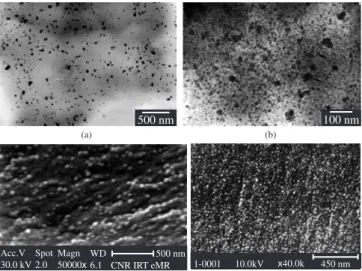
Figure 4 shows SEM and TEM images of the Al2O3-SiC nanocom-posites, while Figure 5 shows the high resolution TEM photographs. SEM results (Figure 4a) reveal agglomeration of the matrix particles. The grains are ~2 µm in size. TEM analysis (Figure 4b) shows a char-acteristic intra/intergranular structure. The intragranular SiC particle is approximately 500 nm in size (Figure 4c). In addition, in the upper part of the HRTEM image (Figure 5), a layer of an amorphous phase is clearly visible in a typically (local) edge-on orientation at the interface of two crystalline phases. However, this layer fades away in the lower section of the image, where the two phases seem to merge with an atomic level lattice match pattern39,103-105.
Figure 6 shows the microstructure of the Si3N4/SiC nanocomposite. One can observe that the nanosized SiC particles are intimately dis-persed through out the matrix material. In addition, they are embedded within the matrix of large Si3N4 grains and at grain boundaries, having inter- and intragranular environments106,107. These morphologies help
understanding the observed properties.
Another aspect to be noted is the mechanism of growth of the two phases in nanocomposites, as illustrated by AFM photographs111.
Figure 7 shows AFM images of two metal oxide-based nanocomposite systems, viz., Fe2O3/Co3O4 and NiO/Co3O4. From Figure 7b-c, one can see the production of big particles in the NiO/Co3O4 system with increasing supported oxide concentration. TEM images of these oxide systems support different growth mechanisms. In the case of Fe2O3/ Co3O4, small clusters of Fe2O3 got wetted on the surface of Co3O4, while NiO grew as isolated particles, showing a larger diameter in the NiO/Co3O4 system.
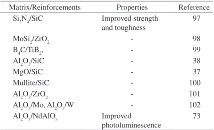
Table 8. Examples of ceramic matrix nanocomposites and their properties.
Matrix/Reinforcements Properties Reference
Si3N4/SiC Improved strength
and toughness
97
MoSi2/ZrO2 - 98
B4C/TiB2, - 99
Al2O3/SiC - 38
MgO/SiC - 37
Mullite/SiC - 100
Al2O3/ZrO2 - 101
Al2O3/Mo, Al2O3/W - 102
Al2O3/NdAlO3 Improved
photoluminescence 73
Table 9. Properties of Al
2O3/SiC nano- and microcomposites 39, 103.
Properties/Material Al2O3/SiCp
composite nanocompositeAl2O3/SiCp
Vickers Hardness [GPa] - 22
Young’s Modulus [GPa] - 383
Fracture Strength [MPa] 106-283 549-646
Fracture Toughness [MPam1/2] 2.4-6.0 4.6–5.5
Table 10. Fracture strength and fracture toughness for Si
3N4/SiC nano- and
microcomposites106, 107.
Properties/Material Si3N4/SiC
composite nanocompositeSi3N4/SiC
Fracture Strength [MPa] 700 1300
Fracture Toughness [MPam1/2] 5.3 7
500 nm
(a) (b) (c)
500 nm 50 nm
Figure 3. TEM micrographs of a) Al2O3/10 wt. (%) Co b) Al2O3/5 vol. %
3.1.2. Ceramic matrix-CNT Systems
The effect of CNT loading on mechanical properties of the SiO2/ CNT nanocomposites is shown in Figure 874. When the volume content
of CNT is lower than 5 vol. %, both bending strength and fracture toughness increase with increasing volume of CNTs. However, loadings
higher than 5% cause decrease in these two properties. At 5 vol. %, the increment in strength and fracture toughness, compared with that of monolithic SiO2, is up to 65 and 100%, respectively. This increase in mechanical properties is due to the large aspect ratio and excel-lent mechanical properties of CNTs, according to the theory of short ibre-reinforced composites 4. The decrease in bending strength at high
4 µm
5.00 k 1.0.2.6 11 5 k 0.1.0.8 0.2 µm
(a) (b) (c)
Figure 4. a) SEM, b) TEM images of Al2O3/SiC nanocomposites; and c) TEM (high magniication) showing a SiC grain [reproduced from references 103, 104 with the kind permission of the authors, Elsevier].
4 nm SiC Al2O3
Figure 5. HRTEM image of the interface region between Al2O3, SiC particles in the Al2O3/SiC nanocomposite [reproduced from reference 39 with the kind permission of the authors, Elsevier].
(a) (b)
SiC SiC
α= Si3N4 α= Si3N4
Intergranular SiC Intergranular SiC
Intragranular SiC Intragranular SiC
0.1 µm 0.5 µm
Figure 6. TEM images of Si3N4/SiC nanocomposites [reproduced from Ref-erence 107 with the kind permission of the authors, Elsevier, the American Institute of Chemical Engineers @ 1997, AIChME].
(a) (b) (c)
Figure 7. AFM images (0.3 x 0.3 µm2) of nanocomposite oxides: a) Fe2O3/
loading is due to the hindrance caused by CNTs during densiication, as they show a higher probability for agglomeration. Consequently, the increased agglomeration leads to the loss of bonding. Also, the higher the loading of CNTs, the higher is their pull out from the matrix during stress transfer274.
Unusual behaviours such as high contact-damage resistance without a corresponding improvement in toughness have also been reported in Al2O3/nanotube composites91,92. The microhardness of these systems
in-creases as the CNT content is increased up to 4 wt. (%). This is probably due to grain size effects and the reinforcement role of CNTs, as shown in Figure 9a. However, the effect decreases again above 4 wt. (%), probably due to the dificulty in dispersing CNTs homogeneously in the composite and to the problem of poor cohesion between CNTs and the matrix107. This trend is also observed in the wear loss and friction
coeficient, as shown in Figure 9b. It can be seen that the wear loss of the 4 wt. (%) composite decreased by nearly 45% as compared to that of the pure matrix. As the CNT content increased above 10 wt. (%), wear losses also notably increased. Friction coeficients decreased gradually as the CNT content increased from 0 to 10 wt. (%), and then dropped sharply at 12.5% CNT content. This trend is attributed to the lubricating properties of the CNTs (graphite)76.
Ma and co-workers prepared SiC/CNTs which showed a 10% improvement in the strength and fracture toughness as compared to the monolithic ceramics108. These modest results were attributed to
nanotube/matrix debonding and crack delection20. As a consequence,
many attempts have been made to develop improved mechanical proper-ties through the incorporation of CNTs in ceramic matrices. However, the observed improvements were not as dramatic as expected. In this context, recently, Zhan et al.109 successfully applied SWCNTs in the
reinforcement of ceramic composites through spark-plasma sintering (SPS), which resulted in a 194% increase in fracture toughness over pure alumina [~9.7 MPam1/2 in the 10 vol. % SWCNT/Al
2O3 nanocomposite].
Also, the electrical properties of ceramic / CNTs nanocomposites have been sharply enhanced, as illustrated in Table 11, due to the outstanding electrical properties of CNTs110.
Using Grifith’s theory and residual stress around nanoparticles in the matrix, Awaji et al.36 have proposed a mechanism for toughening and
strengthening in ceramic-based nanocomposites. They observed that the coeficient of thermal expansion of both matrix and nanoparticles had an effect on residual stresses which was suficient to cause lattice defects such as dislocations around particles in ceramics. Dislocations were also generated around the particle by the nanoparticles in the matrix.
A 24% increase in fracture toughness (3.4-4.2 MPam1/2) over the
matrix was observed in nanograined Al2O3 composite (average diameter 39 nm) containing 10 vol. % MWCNT85, which was attributed to the
oxidation of CNTs before dispersion. In this case the material was produced in three conditions, viz., mixed, hot pressed (1573 K) and
90
80
70
60
50
40
30
20
0 5 10 15 20 25 30
2.4
2.2
2.0
1.8
1.6
1.4
1.2
1.0
CNT volume content %
Bending strength (MP
a)
Frature toughness (MP
am
1/2
)
Figure 8. Effect of CNT volume content on the mechanical properties of SiO2/
CNT nanocomposites [reproduced from reference 74 with the kind permission of the authors, Elsevier].
14
W
ear loss (mg)
3.0
2.5
2.0
1.5
1.0
0.5
0.0 12 14 CNT content wt.
Wear loss Friction coefficient
Friction coef
ficient
0 2 4 6 8 10
0.6
0.5
0.4
0.3
0.2
0.1
0.0 2400
2200 2000 1800 1600 1400 1200 1000
800 600 400 200 0
0 2 4 6 8 10 12
CNT content (wt. (%))
V
ick
ers microhandness (kg.mm
–2)
(a) (b)
Figure 9. Variations of a) microhardness, and b) friction coeficient, wear loss as a function of CNT content in Al2O3/CNT materials [reproduced from refer-ence 76 with the kind permission of the authors, Elsevier].
Table 11. Electrical conductivity of CNT ceramic nanocomposites
[repro-duced from reference 110 with permission of the authors and the American Institute of Physics, USA].
Materials Electrical conductivity
(S/m)
Pure Al2O3 10–12
Al2O3/CNT 5.7-vol. %/Carbon Black 15
Al2O3/SWCNT 5.7-vol. % 1050
Al2O3/SWCNT 10-vol. % 1510
Al2O3/SWCNT 15-vol. % 3345
Al2O3/Fe 4.3-vol. %/ CNT 8.5-vol. % 40-80
sintered to near theoretical density. Figures 10 and 11 show TEM and SEM images of the SiO2/CNT and Al2O3/CNT systems respectively74,76,
where it can be seen that CNTs are homogeneously dispersed in both matrices. This could explain the observed strength properties.
It can be seen that each processing method has its own advantages in yielding appropriate structures and properties for each system, and hence there is need to ind out proper combinations of processing, together with the suitable systems, to arrive at optimum properties.
3.2. Metal matrix nanocomposites
3.2.1. Metal – discontinuous reinforcement systems
Table 12 illustrates examples of some metal matrix nanocomposites and their respective properties.
The α-Fe/Fe23C6/Fe3B system provides a good example of how unique properties may arise from metal nanocomposites. Table 13 shows the measured hardness values (GPa) of the ingot and ribbon samples prepared from this system122. Vickers hardness values of these
two forms of the alloy produced by Branagan and Tang122 were found
to be 10.3 and 11 GPa in the as-solidiied condition. The ribbon variety showed increased hardness with increasing heat treatment temperature, showing a maximum of 16.2 GPa at 973 K [higher than any existing commercial steel and hard alloys] and there after decreasing to 10.5 GPa at 1123 K. This can be compared to the decreasing trend of the ingot type (8 and 6.6 GPa at 873 and 973 K respectively).
The Al/SiC system also illustrates the advantages of metal nano-composites compared to their micro counterparts145-147. Figure 12a shows
plots of Vickers hardness vs. SiC content, while Figure 12b presents plots of Young’s and shear modulus as a function of SiC content. There
is a linear increase in hardness with increasing volume fraction of the harder phase (SiC) until the maximum value of 2.6 GPa for the sample that contains 10 vol. % of SiC. The values of Young’s and shear modu-lus increase signiicantly with increasing SiC content, suggesting the formation of a nanocomposite material containing a brittle phase (SiC) embedded in the ductile Al matrix. Table 14 shows some mechanical properties of both nano- and microcomposites of Al/SiC.
It can be clearly seen that the Al/SiC nanocomposite exhibits no-tably higher Young’s modulus and hardness than its micro counterpart. For example, the nanocomposite shows 12.6% increase in hardness and 105.1% in Young’s modulus145-147. Also, Al/Pb nanocomposites
exhibited improved frictional features119-121. The nanosized dispersoids
lowered the coeficient of friction [0.3 for nanocomposite compared to 0.42 for the microcomposite] due to the formation of a uniform lead-rich tribo layer, with material transfer being an order of magnitude lower than in the micro-sized counterpart. The comparative wear loss of nano and microsized Al/Pb composites is shown in Figure 13119.
Coming to the morphological studies of metal matrix-based na-nocomposites, analysis of the structure and identiication of the nano-phases in α-Fe/Fe23C6/Fe3B alloys using X ray diffraction and TEM with EDAX revealed the existence of two cubic and one tetragonal phase. The three phases exhibited the size of 4 µm [4,000 nm] in the ingot alloy, while in the heat-treated ribbon alloy the size of the phases was in the range of 100-130 nm. Based on these, the observed hardness was attributed to the nanostructure and to the super saturation of Cr and W above their equilibrium solubility in Fe. These studies also suggested the possible synthesis of very hard and inexpensive materials for three bodies wear applications and to replace expensive hard metals such as in cobalt-based materials. Figure 14 shows TEM/SAED images of this
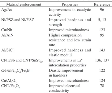
Table 12. Examples of metal nanocomposites and their properties.
Matrix/reinforcement Properties Reference
Ag/Au Improvement in catalytic
activity
96
Ni/PSZ and Ni/YSZ Improved hardness and
strength 5, 13
Cu/Nb Improved microhardness 123
Al/AlN Higher compression
resistance and low strain rate
95
Al/SiC Improved hardness and
elastic moduli
143
CNT/Sb and CNT/SnSb0.5 Improvements in Li+
intercalation properties
136, 137
α-Fe/Fe23C6/Fe3B Drastic improvement
in hardness 122
Cu/Al2O3 Improved microhardness 124
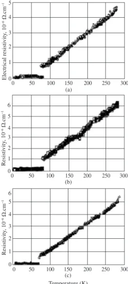
CNT/Fe3O4 Improved electrical
conductivity 78
Table 13. Hardness values (GPa) of the ingot and ribbon samples prepared
from the Fe/Fe23C6/Fe3B nanocomposite [reproduced from reference 122 with the permission of the Authors and Elsevier].
Sample Ingot Ribbon
As-solidiied 10.3 11.0
600 °C 8.0 11.0
650 °C - 15.6
700 °C 6.6 16.2
750 °C - 12.2
800 °C 6.5 12.0
850 °C - 10.5
1 µm (a)
100 nm (b)
1 µm
Figure 10. TEM image of CNT, SiO2 nanocomposite mixture[reproduced from reference 74 with the kind permission of the authors, Elsevier].
Figure 11. SEM micrographs of Al2O3/CNT materials: a) at low
nanocomposite. The three iron-containing phases are homogeneously distributed over the entire material122.
In the case of Al/SiC nanocomposites (Figure 15), only two phases are visible in the TEM images: SiC (granular ine grains) and Al (overall matrix). No more sharp ring-spot patterns have appeared in the electron diffraction pattern (SAED), indicating the formation of ine, nanosized powders147 containing the brittle SiC phase embedded
in the ductile Al matrix.
Other metal-ceramic nanocomposites are shown in the SEM and TEM photographs of Figure 16. Figure 16a is a SEM micrograph of Fe/ MgO composite heat treated at 873 K and reduced at 1073 K11. Volume
changes occurred due to O2 atoms released from Fe2O3 during reduc-tion. Figure 16b, c presents TEM micrographs of uniformly distributed nanosize ceramic particles in Al and Ag metal matrices95,96 respectively.
Nearly spherical particles of Ag isolated from each other can be seen in Figure 16c. This study revealed that Ag particles of size smaller than pore size (10 nm) are size-deined and stabilized. Similar observations have been made with other noble metals such as Au and Pd.
In the case of Al-Pb nanocomposites, micrographs showing the worn surfaces (not shown here) revealed delamination in the early
V
ick
ers hardness (GP
a)
SiC content, x (vol. %) SiC3 Al100-x composites
3.0
2.5
2.0
1.5
1.0
0 2 4 6 8 10 12
SiC3 Al100-x composites
Y
oung’
s modulus (GP
a)
110
105
100
95
90
85
80
75
0 2 4 6 8 10 12
60
55
50
45
40
35
Shear modulus (GP
a)
SiC content, x (vol. %)
Young’s modulus Shear modulus
Table 14. Properties of Al/SiC nano- and microcomposites145-147.
Properties / Material Al/SiC
composite
Al/SiC nanocomposite
Young’s modulus (GPa) 88.4 100
Hardness (Hv) (Kg/mm2) 78 160
Figure 12. Correlation between SiC content, x, Vicker’s hardness, Young’s modulus, shear modulus of consolidated Al100-x/SiCx nanocomposites [repro-duced from reference 147 with the kind permission of the author, Elsevier].
14
12
10
8
6
4
2
0
0 10 20 30 40 50 60
W
ear v
olume
Load (N) Tiwari et al.
Present study
Figure 13. Wear loss of nanosized vs. microsized leaded Al alloys [reproduced
from reference 78 with the kind permission of the authors, the American Chemical Society, USA].
Fe23C6
α-Fe Fe3B
200 nm
100 nm
Figure 14. TEM images, corresponding SAED for the nanocomposite α-Fe/
Fe23C6/Fe3B ribbons heat-treated at 850 °C [reproduced from reference 122 with the kind permission of the authors, Elsevier].
Al matrix
Al matrix
SiC SiC
(b)
(a) 20 nm
![Figure 4. a) SEM, b) TEM images of Al 2 O 3 /SiC nanocomposites; and c) TEM (high magniication) showing a SiC grain [reproduced from references 103, 104 with the kind permission of the authors, Elsevier].](https://thumb-eu.123doks.com/thumbv2/123dok_br/18877883.421948/11.892.84.830.105.366/figure-nanocomposites-magniication-showing-reproduced-references-permission-elsevier.webp)
![Figure 9. Variations of a) microhardness, and b) friction coeficient, wear loss as a function of CNT content in Al 2 O 3 /CNT materials [reproduced from refer- refer-ence 76 with the kind permission of the authors, Elsevier].](https://thumb-eu.123doks.com/thumbv2/123dok_br/18877883.421948/12.892.454.822.595.765/variations-microhardness-friction-coeficient-materials-reproduced-permission-elsevier.webp)
![Figure 12. Correlation between SiC content, x, Vicker’s hardness, Young’s modulus, shear modulus of consolidated Al 100-x /SiC x nanocomposites [repro-duced from reference 147 with the kind permission of the author, Elsevier].](https://thumb-eu.123doks.com/thumbv2/123dok_br/18877883.421948/14.892.458.811.103.380/figure-correlation-hardness-consolidated-nanocomposites-reference-permission-elsevier.webp)

![Figure 27. Dependence of tensile modulus (E) at 120 °C on clay content for organomodiied montmorillonite-, saponite-based nanocomposites [re-produced from reference 208 with the kind permission of the authors, the Materials Research Society].](https://thumb-eu.123doks.com/thumbv2/123dok_br/18877883.421948/19.892.77.828.895.1124/dependence-organomodiied-montmorillonite-nanocomposites-reference-permission-materials-research.webp)
