ISSN 0104-6632 Printed in Brazil
Brazilian Journal
of Chemical
Engineering
Vol. 21, No. 01, pp. 93 - 101, January - March 2004
A NEW ROLE FOR REDUCTION IN PRESSURE
DROP IN CYCLONES USING COMPUTATIONAL
FLUID DYNAMICS TECHNIQUES
D. Noriler¹, A. A. Vegini
2, C. Soares
1, A. A. C. Barros
1, H. F. Meier and M. Mori
2*1
Laboratório de Fluidodinâmica Computacional. Departamento de Engenharia Química, Centro de Ciências Tecnológicas, Universidade Regional de Blumenau, Cx. P. 1507, CEP 89.010-971, Blumenau - SC, Brasil.
E-mail: [email protected], E-mail: [email protected] 2
Departamento de Processos Químicos, Faculdade de Engenharia Química, UNICAMP, Cx. P. 6066, CEP 13.081-970, Campinas - SP, Brasil.
E. mail: [email protected].
(Received: April 15, 2003 ; Accepted: July 11, 2003)
Abstract - In this work a new mechanical device to improve the gas flow in cyclones by pressure drop reduction is presented and discussed. This behavior occurs due to the effects of introducing swirling breakdown phenomenon at the inlet of the vortex finder tube. The device consists of a tube with two gas inlets in an appositive spiral flux that produces a sudden reduction in the tangential velocity peak responsible for practically 80 % of the pressure drop in cyclones. In turn, peak reduction causes a decrease in pressure drop by a breakdown of the swirling, and because of this the solid particles tend to move faster towardthe wall , increasing collection efficiency. As a result of this phenomenon the overall performance of cyclones is improved. Numerical simulations with 3-D, transient, asymmetric and anisotropic turbulence closure by differential Reynolds stress for Lapple and Stairmand standard geometries of 0.3 m in diameter, show a reduction in pressure drop of 20 % and a shift of the tangential velocity peak toward the wall. All numerical experiments were carried out with a commercial CFD code showing numerical stability and good convergence rates with high-order interpolation schemes, SIMPLEC pressure-velocity coupling and other numerical features.
Keywords: computational fluid dynamics (CFD), cyclones, pressure prop and turbulence.
INTRODUCTION
Cyclones have been widely used in chemical processes since the beginning of the twentieth century for downstream and upstream unit operations. In the fluid catalytic cracking process (FCC process), for example, cyclones are very important equipment to guarantee performance and rentability. Currently, researchers and engineers in the petroleum industries are striving for an overall collection efficiency near 99.999 % in systems composed of a network of primary and secondary cyclones. Pressure drop is also very important for process savings. In the preheater tower at a cement industry for example, a reduction in
pressure drop is fundamental for reduction in the cost of cement where each kcal of energy saved per kilogram of product plays an important role in the success of the cement plant.
others. Engineers and scientists throughout the world are dedicating more and more time to attempting to understand the fluid dynamics of swirling turbulent flow, making it possible to seek alternatives for improving cyclone performance. Optimization of geometry and optimal operation are the main aspects observed in the current developments and research.
Dyakowski and Williams (1993), Cristea et al. (1994), Meier and Mori (1999), and Meier et al. (2002) developed numerical studies with experimental data on bench and industrial scales with geometries like Lapple and Stairmand for verification and validation in CFD 3-D, by using transient and turbulent models with the capability to represent the main phenomena of swirling flow in gas cyclones. The authors observed in all cases a poor representation of conventional turbulence closures using the isotropic behaviour of the Reynolds stress in the standard k-ε form. Thus, it was clear that the anisotropy of Reynolds stress has an important role in predicting the tangential velocity profiles, and two closures with two approaches were considered: the hybrid model composed of a combination of the k-ε model and the mixture length theory of Prandtl (k-ε -Prandtl model) in a symmetric 3-D physical domain and a second-order closure like Reynolds stress modelling (differential stress model - DSM ) in an asymmetric 3-D domain. Both models and
approaches were tested with a large variation in geometry and operational conditions showing good agreement with experimental data from the literature. The anisotropic symmetry approach is very similar to the perfect mixture in chemical reactors with ideal behaviour. On the contrary, the anisotropic asymmetry approach shows deviation from ideal behaviour. Of course, the second approach requires more computational time and must be carefullyused by engineers in practical situations.
The main objective of this work is to apply the computational fluid dynamics techniques in the solution of a 3-D transient and asymmetric model with Reynolds stress second-order turbulence closure, in an attempt to analyse the new device for reduction in pressure drop in cyclones.
This kind of methodology can be more useful than traditional experimental studies. The cost of numerical implementation is much lower than the cost of
building an experimental device, and different
geometric modifications can be analysedat the same time. The purpose of this work is the implementation and analysis of a mechanical device in order to study the reduction in pressure drop in parallel with interpretation of numerical results and scientific visualization of the swirling flow in cyclonesby using a rigorous phenomelogical model coupled with computational fluid dynamics techniques.
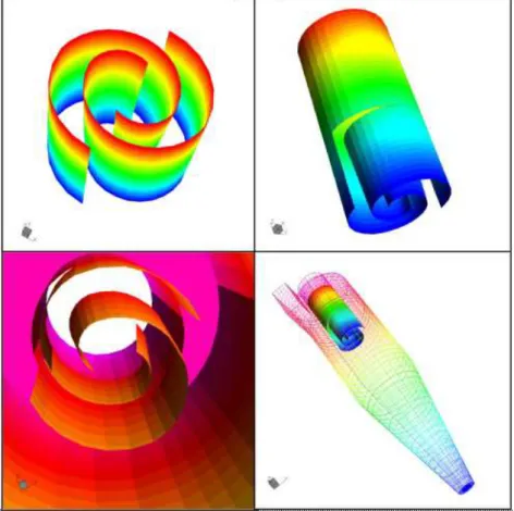
The mechanical device is based on the principle that 80% of the pressure drop is directly influenced by tangential velocity peak. Therefore, the idea is to decrease the velocity peak in the vortex finder of the cyclone by using the fluid dynamics behavior of the swirling flow, i.e.,., the main vortex is divided into two opposite vortices in the finder by two inlets in a spiral format which produces a shock between the streamlines, thereby increasing the static pressure of the system. Figure 1 shows in detail the format of the device and its location in the vortex finder tube.
The mathematical modeling using in this work is presented in the following section. It is also important to point out that the model has been previously submitted to extensive corroboration studies (Meier et al., 2000).
MATHEMATICAL MODELLING
The transport equation, better known as the Navier-Stokes equations used in this work to predict the swirling, turbulent single-phase flow in cyclones, can be written as follows:
Mass conservation equation
( )
. v 0
t
∂ρ+ ∇ ρ =
∂ (1)
Momentumconservation equation,
( ) ( )
v(
)
. vv g . - v'v
t
∂ ρ
+ ∇ ρ = ρ + ∇ σ ρ
∂ ' (2)
where σ is the stress tensor and can be defined as
( )
T2
σ pI v I v v
3
= − − µ∇ + µ ∇ + ∇
. (3)
where ρ is the fluid density, v is the velocity field, µ is the molecular viscosity, and I is the identity tensor.
The last term on the right of Equation 2, ρv'v', is the time average of the dyadic product of fluctuation velocities, and it is referred to as the Reynolds turbulent stress.
The turbulence closure applied in this work is a second-order closure based on the conservation equations for each Reynolds stress component. The
model is well known as the differential stress model (DSM) and for incompressible flows can be expressed as
( ) ( )
( )
Ts
DS
v'v' C k
. v'v'v . v'v' v'v'
t
2
P I.
3
∂ ρ
+ ∇ ρ = ∇ ρ ∇
∂ σ ε
+ − φ − ρε
(4)
P represents shear stress production and can be expressed as
( ) ( )
TP= −ρ v'v' ∇v + ∇v v'v'
(5)
and φ is a correlation for pressure force, which in incompressible flow can be written as follows:
1 2
φ = φ + φ (6)
where
1 1S
2 C v'v'- kI
k 3
ε
φ = −ρ
(7)
and
2 2S
2
C P P I
3
φ = − −
. (8)
In this case, P is the trace of the tensor P, and CS, σDS, C1S and C2S are constants of the model.
It is necessary to include an additional equation for the rate of dissipation of kinetic energy that appears in Equation (4).
( )
( )
S( )
2
1 2
C k
. v . v'v'
t
C P C
k k
ε
∂ ρε
+ ∇ ρ ε = ∇ ρ ∇ε
∂ σ ε
ε ε
+ − ρ
(9)
and k is obtained directly by its definition,
2
k=1/ 2 v' (10)
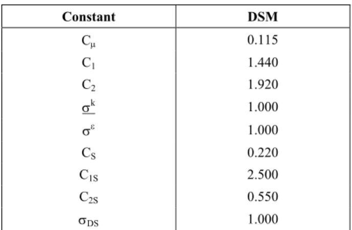
Table 1: Constants of the DSM.
Constant DSM
Cµ 0.115
C1 1.440
C2 1.920
σk 1.000
σε 1.000
CS 0.220
C1S 2.500
C2S 0.550
σDS 1.000
NUMERICAL METHODS
The numerical method applied to solve the model was the finite volume method (MVF) with a multiblock structure in a generalized co-ordinate system for the numerical grid. The numerical algorithm SIMPLEC was applied to the pressure-velocity coupling, with a high-order interpolation scheme (HIGHER UPWIND).
The Rhie Chow algorithm with the AMG procedure (algebraic multi-grid) for solution of the system of equations was used to prevent numerical errors like “check-boarding” and “zig-zag” due to the collocated grid. In this case, all variables are calculated in the centre of each cell, and errors due to the non-orthogonality of cells are generated during the build of the numerical structure.
Details about the numerical method can be found in Meier (1998), Meier and Mori (1998 e 1999),
Maliska (1995), Patankar (1980) and CFX4-4 User Guide (2001).
Details about the numerical experiments
procedure for obtaining a stable solution with DSM are available in Meier et al. (2000).
TEST CASES
The cyclones chosen for analyses of perturbation caused by additional new devices are of two types, Lapple and Stairmand. This choice was based on the fact that a large quantity of data related to these types ofcyclones can be found in the literature.
Table 2 containsthe geometric features of Lapple and Stairmand cyclones.
Analysisof cyclones with a diameter of 0.3 meters (DC) was based on the operational conditions
and physical properties of the fluid, as described in Table 3.
Table 2: Standard geometric features of Lapple and Stairmand cyclones.
Cyclone
Lapple Stairmand
BC/DC 0.250 0.200 DO/DC 0.500 0.500
HC/DC 0.500 0.500 LC/DC 2.000 1.500
SC/DC 0.620 0.500 ZC/DC 2.000 2.500
Table 3: Physical properties and operational conditions of the test cases.
Physical Properties Operational Conditions
ρ = 1.000 kg/m3 Vin = 15.000 m/s
µ = 1.800.10-5 kg/m.s P∞ = 101325.000 Pa
RESULTS AND ANALYSIS
All numerical solutions were obtained using a PC PENTIUM IV, 1.6 Ghz and 1.0 Gb RAM with CFX 4.4 from AEA Technology for Windows NT.
Figure 2 shows the numerical grid used in this study, which offers a solution independent of the number of cells in the grid.
The CPU time for each case was 72 hours using a grid with about 40000 cells. To guarantee reproducibility of the results, the numerical grids for all Lapple and Stairmand cyclones were kept the same with or without the device.
Results obtained on pressure drop in all test cases are compared in Figure 3. A substantial decrease in the pressure drop (about 20%) is obtained when the proposed device is implemented.
Lapple without Device
Lapple with Device
Stairmad without Device
Stairmand with Device
0 100 200 300 400 500 600 700
Pre
ss
u
re
Drop
(Pa
)
-22.7 % -23.8 %
Figure 3: Pressure drop in cyclones.
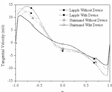
Figures 4 and 5 illustrate the tangential velocity profile at 15 cm below the device and at the exit of finder, respectively.
InFigure 4 we can see that the negative effects of
the mechanical device cannot be observed in the
tangential velocity fields. A deviation in the tangential velocity peak in the direction of the wall was observed, but this represents a positive effect, mainly for the efficiency analysis. It can be observed in Figure 5 that the velocity peaks decrease in the vortex finder region when the device is used. This behaviour confirms the decrease in pressure drop.
Figure 6 illustrates the pressure maps for all test cases, and it is possible to observe that the pressure differential between the centre of the cyclone and the
peripheries decreases, the high-pressure region is concentrated near the wall, and the low-pressure region is concentrated exclusively in the vortex finder region. Assuming the pressure difference as the driving force for particle drag, it is possible that the new device increases cyclone efficiency.
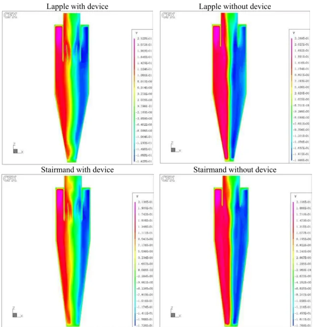
Figure 7 shows the tangential velocity fields, and it is evident that the high-velocity regions are transferred to the region near the wall, concentrating the centrifugal field that is responsible for the increase in collection efficiency. It is possible to note that the swirling flow is symmetrical, explaining the good results obtained when a 3D axisymmetric modification, 2D domain is applied to the representation of fluid dynamic patterns in cyclones.
Figure 5: Tangential velocity at the exit of the vortex finder tube.
Lapple with device Lapple without device
Stairmand with device Stairmand without device
Lapple with device Lapple without device
Stairmand with device Stairmand without device
Figure 7: Tangential velocity maps for Lapple and Stairmand cyclones with and without the mechanical device.
CONCLUSIONS
Based on the results obtained in this work, it is possible to conclude that implementation of the mechanical device generates a decrease in the
pressure drop of about 20%, which causes a
reduction in energy consumption in this separation
process and has positive effects on collection
efficiency.
Although in this study the gas-solid system is not analysed, there is evidence of an increase in efficiency, since the tangential velocity peak is transferred to the wall and the pressure field becomes more homogeneous with the mechanical device,very similar to the symmetric behaviour in cyclones.
An experimental study with the objective of evaluating the geometric conditions and the efficiency of the cyclone is suggested for consolidation of this study. It is necessary to comment that this mechanical device can be installed in any cyclone, since it is merely an adaptation of the vortex finder region.
NOMENCLATURE
Latin Letters
Bc inlet section length, m
Do vortex finder diameter, m
Du underflow diameter, m
g gravitational acceleration vector, m/s2 Hc height section length, m
I identity tensor
k turbulent kinetic energy, m2/s2 Lc cylindrical section height, m
p pressure, Pa
P mean shear stress production, Pa/s P trace of the tensor P, Pa/s
Sc vortex finder height, m
t time, s
v velocity vector, m/s Zc conical section height, m
Greek Letters
ε rate of dissipation of turbulent energy, m2/s3
φ pressure force correlation, Pa
µ viscosity, kg/ms
ρ density, kg/m3
σ normal stress tensor, Pa
REFERENCES
CFX4 for Windows NT. CFX4-4 User Guide, AEA Technology. Oxfordshire, United Kingdom(2001). Cristea, E. D., Malfa, E., and Coghe, A., 3-D
Simulation and Experiments of Cement Rotary Kiln Preheater Top Cyclone. Proceedings of Fluent European User’s Group Meeting, Harrogate, U. K., C54 (1994).
Dyakowski, T. and Williams, R.A., Modelling Turbulent Flow in a Hydrocyclone Operating without an Air Core. Chem. Eng. Sci., vol 48, nº 6, pp. 119-128 (1993).
Maliska, C.R., Transferência de Calor e Mecânica dos Fluidos Computacional. CTC Editora, Rio de Janeiro, RJ (1995).
Meier, H.F., Kasper, F.R.S., Peres, A.P., Huziwara, W.K., and Mori, M., Comparison between Turbulence Models for 3-D Turbulent Flows in Cyclones In: 21st Iberian Latin American Congress on Computational Methods in Engineering, Rio de Janeiro.CILANCE2000. PUC RIO, vol.1( 2000). Meier, H.F. and Mori, M., Anisotropic Behavior of
the Reynolds Stress in Gas and Gas-Solid Flows in Cyclones. Powder Technology, vol.101, pp.108-119 (1999).
Meier, H.F., and Mori, M. Gas-Solid Flow in Cyclones: The Eulerian-Eulerian Approach. Computers and Chemical Engineering., vol.22, pp.64 -644 (1998).
Meier, H.F., Ropelato, K., Forster, H., Iess, J J., Mori, M., Computational Fluid Dynamics (CFD) zur Berechnung und Auslegung von Zyklonen - Teil 1.” ZKG International,vol.55, nº 04, pp.6-75 (2002a).
Meier, H.F., Ropelato, K., Forster, H., Iess, J J., Mori, M.,Computational Fluid Dynamics (CFD) zur Berechnung und Auslegung von Zyklonen -Teil 2. ZKG International - Cement-Lime-Gypsum. vol.55, nº.06, pp.5 -64 (2002b).