TREATMENT OF LF SLAG TO PREVENT POWDERING DURING COOLING
S. Ghorai a,*, G.K. Mandal a, S. Roy b, R.K. Minj a, A. Agrawal a, D.P. Singh a, A. Kumar cR.B.V. Ramna c a CSIR-National Metallurgical Laboratory, Jamshedpur, India
bFormerly with CSIR-National Metallurgical Laboratory, Jamshedpur as Summer Research Fellow, Indian Academy of Sciences, India
c Tata Iron & Steel Company Limited, Jamshedpur, India
(Received 26 February 2016; accepted 30 January 2017) Abstract
The polymorphic transformation of the monoclinic β-polymorph to the orthorhombic γ-polymorph of di-calcium silicate at around 500°C during cooling results in disintegration of slag. The slag generated, during the production of thermo mechanically treated steel in ladle furnace at M/s Tata Steel Limited, Jamshedpur, India, behaves in similar manner. An attempt has been made to prevent the crumbling of ladle furnace slag. The experiments were conducted in 10 kg air induction furnace. Various types of silica source were used to prevent the disintegration of ladle furnace slag by reducing the basicity and optimizing the additives amount. Apart from silica sources, other additives like borax and barium carbonate were also used to stabilize the β phase. Present investigation reveals that disintegration of ladle furnace slag can be prevented either by addition of 0.2% borax or 2% barium carbonate. Dust formation can also be prevented by decreasing the ladle furnace slag basicity to about 1.7. Toxicity Characteristic Leaching Procedure test, of the borax and barium carbonate treated slag samples, indicates that barium carbonate treated slag cannot be used for the dusting prevention as it contains high level of barium.
Key words: LF Slag, Di-calcium silicate, Crumbling, Basicity
* Corresponding author: [email protected]
S e c t i o n B : M e t a l l u r g y
DOI:10.2298/JMMB160226004G
1. Introduction
High percentages of lime have been commonly used in the various iron and steel making processes for mostly capturing gangue as well as refining the liquid metal leading to the formation of lime rich slag. The highly basic slag generally contains di-calcium silicates. It is well documented that di-calcium silicate (2CaO.SiO2 or C2S) undergoes polymorphic transformation during cooling and formed phases like α, αꞌH, αꞌ, β & γ in descending order [1]. At around 500°C, β-C2S transforms to γ-C2S. The transformation of C2S from monoclinic β-polymorph to the orthorhombic γ-polymorph results in an increase in volume of about 12-15%. Therefore, high internal stresses are built up leading to complete disintegration of slag. Presence of fine particles in the disintegrated slag causes problem not only to the working environment at the plant site but also create trouble in its subsequent reuse/dumping. Literature report suggests [1] that the problem of powdering can be prevented by adopting three potential routes, namely, a) chemical stabilization by additions, b) change in slag chemistry and c) fast cooling.
Prevention of crumbling has been mostly
addressed by various researchers [1-16] either by adding small amount of additives to the slag which stabilizes β phase or by changing chemistry of the slag. Seiki et al [1] did some pioneering work and proposed the criteria of choosing the material to stabilize the β phase based on the atomic radius. They reported that the replacement of some Si4+by an ion having ionic radius smaller than that of Si4+ or replacement of Ca2+ ion having ionic radius greater than that of Ca2+ion. This replacement suppresses the Ca2+migrations and SiO4-rotations required for the β to g transformation. The larger differences of ionic radius will have better influence on prevention of β to
0.5 to obtain uniformly lumpy slag. Pontikes et al.[7] reported that basicity of 2 gives stable slag by adding fly ash. Parker et al[10] defined compositional limits for disintegrating slags based on the stability field of C2S in the CaO–MgO–SiO2–Al2O3slag system with an adjustment for the calcium sulphide content. They proposed conditions to reduce the amount of C2S in the slag. A large number of synthetic and industrial slags were tested in a separate study to further improve the criteria proposed by Parker et al[10] and found the above criteria to be reliable except at MgO levels of 10 wt% or more [9]. The red mud produced from aluminium industry can also be used in the stabilization of steel slag generates in convertor or electric furnace. The red mud on melting generates Al2O3, SiO2, Na2O, K2O and Fe2O3 and forms 3CaO.Al2O3, 2CaO.2SiO2, 2CaO.Al2O3.SiO2 [11] to prevent crumbling. Also, instead of using chemical additions, the β to γ transformation of C2S can also be avoided by rapid cooling [12]. This technique is used in the cement industry to prevent the formation of γ-C2S [7]. A very high cooling rate of around 50oC/s is required to stabilize the slag, i.e. arresting C2S in its β polymorphic form [13-15]. It is also observed that EAF steel slag can be stabilized by air granulation [16] due to fast cooling.
Slag produced in the ladle furnace (LF) for the production of thermo mechanically treated (TMT) steel at M/s Tata Steel Limited (TSL), Jamshedpur, crumbles dramatically. The presence of C2S in the LF slag of TSL causes the powdering of the slag. The average composition of this high basicity LF slag is 55-62% CaO, 23-27% SiO2and 5-7% Al2O3. In the present investigation an attempt has been made to prevent crumbling of ladle furnace slag by adding various types of silica source. Also, some experiments were carried out using borax as well as barium carbonate.
2. Experimental
2.1 Raw materials
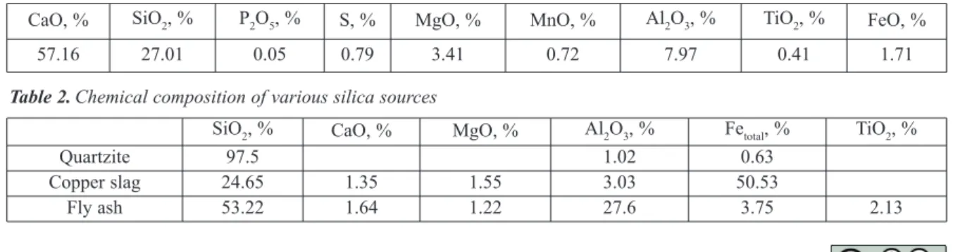
Ladle furnace slag produced during the production of TMT grade steel at TSL, Jamshedpur was used as base material for this study. The chemical composition of the LF slag is presented in Table 1.
The composition of the slag was varied by changing the basicity of the slag with the addition of silica. Different silica sources, used for this investigation to reduce the slag basicity, are quartzite, silica sand, copper slag and fly ash. The chemical compositions of these silica sources are presented in Table 2. To stabilize the β phase, high purity laboratory grade borax and barium carbonate were used.
2.2 Experimental procedure
As received high basicity LF slag was melted in a 10 kg capacity air induction furnace. A graphite crucible was used for the melting experiments in order to avoid the difficulty of melting the slag in the induction furnace. For each experiment, 1 kg of as received LF slag was melted. Various amount of additives were added in the molten slag bath placed inside the furnace after achieving the bath temperature of around 1650oC, as measured by optical pyrometer. After five minutes of addition, molten slag was tapped into a preheated clay moulded graphite crucible. The slag was allowed to cool in air to study the effect of addition of various additives on disintegration of the LF slag.
2.3 Theoretical calculation
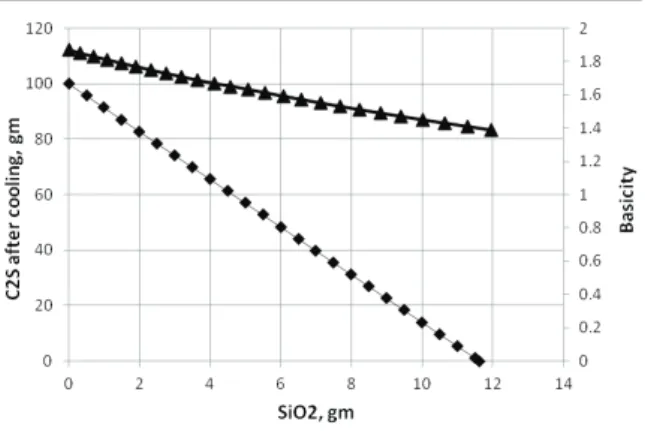
The variation in amount of di-calcium silicate with the addition of silica was estimated using the commercial thermodynamic simulation software package FactSage 6.4 [17]. The calculation was performed using the Equilib module with FactPS database. For the calculation, 100 gm of pure di-calcium silicate was used as a starting material and then different amount of SiO2 was added. Figure 1 shows the estimated variation in amount of di-calcium silicate with the increase in addition of SiO2. The change of basicity (CaO/SiO2) with the addition of SiO2is also presented in the figure. It clearly reveals that both the amount of di-calcium silicate and basicity decrease with the increase in addition of SiO2. Theoretical prediction also indicates that after addition of about 12 gm of SiO2and at slag basicity (CaO/SiO2) of about 1.39, presence of C2S in the slag vanishes. Based on this theoretical study, it is
Table 1.LF slag composition
Table 2.Chemical composition of various silica sources
CaO, % SiO2, % P2O5, % S, % MgO, % MnO, % Al2O3, % TiO2, % FeO, %
57.16 27.01 0.05 0.79 3.41 0.72 7.97 0.41 1.71
SiO2, % CaO, % MgO, % Al2O3, % Fetotal, % TiO2, %
Quartzite 97.5 1.02 0.63
Copper slag 24.65 1.35 1.55 3.03 50.53
envisaged to decrease the basicity of the as received LF slag by the addition of SiO2 to prevent the crumbling. The initial basicity of the as received LF slag used for this study was 2.12. Therefore, first set of experiments were carried out to optimize the basicity by the addition of quartzite as a silica source (more than 97% SiO2).
3.0 Results
3.1 Changing chemical composition
3.1.1 Quartzite addition
By adding different percentage of quartzite, the basicity of LF slag is decreases from 2.12 to 1. The treated slags are presented in the figure 2. The figure reveals that at and below 1.7 basicity, the LF slag does not disintegrate. Thus, 1.7 basicity is taken as optimum basicity. Subsequently, several experiments were conducted using different silica sources at 1.7 basicity.
3.1.2 Copper slag addition
Copper slag generated during the smelting is mostly used for land filling. It contains 24.61% SiO2. This copper slag was used as a silica source to
stabilize the LF slag. Two experiments were conducted at 1.6 and 1.7 basicity. The treated slag does not crumble with the addition of copper slag as shown in the figure 3.
3.1.3 Fly Ash addition:
Huge amount of fly ash is generated in the thermal power plant. It is a good source of silica. Fly ash from National Thermal Power Corporation Limited (NTPC), Talcher, India is also used for the present study and it contains 53.22% SiO2. The experiments were conducted by varying the basicity level (1.7, 1.8 and 1.9) and the results are presented in the figure 4. It demonstrates that disintegration of LF slag was prevented when the basicity was 1.7.
3.2 Stabilization of β phase
3.2.1 Borax addition
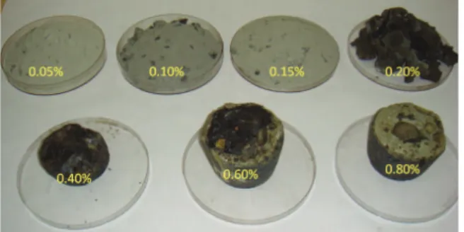
The addition of borax in the liquid LF slag was varied from 0.05% to 0.8%. The treated slags are presented in the figure 5. The figure reveals that with lower amount of borax addition (upto 0.15%), the disintegration of LF slag cannot be prevented. However, at higher level of borax additions (0.2% or more), stabilization of LF slag can be obtained. Therefore, 0.2% of borax addition can be taken as the optimum percentage of borax required to prevent the crumbling of LF slag. Borax contains both sodium and boron ions having ionic radius 1.02 Å and 0.23 Å [18], respectively. Therefore, the ionic radius of boron is less Figure 1.The variation of amount of di-calcium silicate in
the cooled slag against SiO2addition based on theoretical calculation
Figure 2.Treated LF slag at different basicity with quartzite addition
Figure 3. Treated slag at different basicity with addition of copper slag
than that of silicon (0.4 Å); while the ionic radius of sodium is greater than that of calcium (0.99 Å). Thus, suppression of the Ca2+migrations and SiO4- rotations [1] due to substitution of both silicon ion and calcium ion help in prevention of disintegration of LF slag.
3.2.2 Barium carbonate addition
The laboratory grade barium carbonate addition to the LF slag was varied from 0.5 to 10%. The treated slags are presented in the figure 6. The figure demonstrates that with increasing percentage of barium carbonate addition, the dust percentage in the treated slag decreases. At 2% addition, no crumbling was observed. Therefore, 2% of barium carbonate addition can be taken as the optimum percentage of barium carbonate required to prevent the crumbling of LF slag. Prevention of crumbling is mainly due to the
replacement of Ca2+ ion (0.99 Å) with barium ion having ionic radius 1.35 Å [18] leading to suppression of the Ca2+migrations [1] required for the β to γtransformation.
3.3 Microstructural analysis of treated slag
A Wavelength-Dispersive X-Ray Spectroscopy (WDS) analysis of some of the treated slag samples were carried out using Electron Probe Micro Analyser (EPMA), Model JXA-8230, JEOL. Some typical microstructure along with the point analysis data are presented in the figure 7. WDS analysis reveals that wt% FeO in the final slag in almost all the analyzed points is less than 0.5% as compare to the 1.7% in the initial slag indicating some reduction of FeO during melting experiments due to the use of graphite Figure 5.Treated LF slag after addition of different
percentage of borax
Figure 7.WDS analysis of treated LF slag; (a) quartzite added slag with 1.7 basicity, (b) 0.2% borax added slag and (c) 2% barium carbonate added slag
crucible. Presence of white contrast areas in the micrographs, particularly, in borax and barium carbonate treated slag specimens, can be observed. The analysis suggests that those white contrast areas are rich in alumina. The WDS analysis of 1.7 basicity quartize treated slag sample (refer Figure 7(a)) reveals that the basicity (CaO/SiO2ratio) of different points varies in the range of 1.4 to 1.8. Presence of low intensity peaks of boron in some of the points were detected in case of borax treated sample as very low amount of borax was used to stabilize the LF slag as can be seen in figure 7(b). WDS analysis confirms the presence of BaO of the barium carbonate treated slag specimens (refer Figure 7(c)).
3.4 Compressive strength of treated LF slag
To measure the compressive strength of the treated slag, cubes of 1 cm length were prepared. Theses samples were tested in a Servo Electric mechanical testing system, Instron 8862. The strength data are presented in the Table 3. These data reveal the treated slags are very hard compare to natural rock (30-40 N/mm2). Therefore, the treated slag can be used as a replacement for natural rock for road construction purpose.
3.5 Toxicity analysis
The TCLP (Toxicity Characteristics Leaching Procedure) is designed to determine the mobility of both organic and inorganic analytes present in liquid, solid and multi-phase wastes. The intent of this leachate procedure is to simulate the conditions that may be present in a landfill where water may pass through the land-filled waste and travel into the groundwater carrying the soluble materials with it. This procedure does not apply to volatile organic analytes.
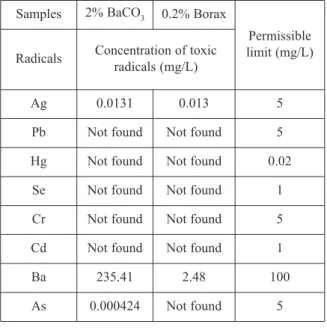
TCLP test has been conducted for both 0.2% borax and 2% barium carbonate treated LF slag samples as per US Environmental Protection Agency (USEPA) test method 1131. As per this test method, eight radicals are identified for testing. The results are presented in the Table 4 along with the permissible limit of these eight radicals. It reveals that barium is more than the permissible limit for the barium carbonates treated slag, while other seven radicals are
within the permissible range. However, in case of borax treated LF slag, the concentrations of these eight metallic radicals are within the permissible limit as per USEPA. Therefore, barium carbonate cannot be used although it prevents crumbling of LF slag. WDS analysis also confirms that barium carbonate treated slag contains high percentage of BaO.
4. Discussion
The laboratory scale experiments reveal that there are only two kind of options are available for the prevention of crumbling of ladle furnace slag. One is the addition of borax, which will stabilize the β phase. Other one is the decreasing basicity to 1.7 by using silica. To implement the results to the plant scale, there are few things needed to be considered.
4.1 Borax addition
The major advantage of borax addition is that only 2kg/ton of LF slag is required to prevent dusting. This small amount can be added to the ladle furnace itself.
4.1.1 Boron pick up by steel
An equilibrium thermodynamic calculation is carried out to study the boron pick up by liquid steel due to addition of B2O3 in slag using FactSage 6.4 [17] by combining FSstel and FToxid databases. Equilibrium slag metal reactions are considered at 1600oC. For a steel of composition as given in Table 5 was equilibrated with slag of composition as given in Table 6. At equilibrium, the amount of boron pick up by the liquid is given in Table 7. The boron level in the liquid steel was within the permissible limit.
Table 3.Compressive strength of treated slag
Table 4.TCLP test results for both borax and barium carbonate treated slag
Treated LF slag Compressive strength, N/mm2
0.2% Borax 102.5
2% BaCO3 47.1
1.7 basicity (Quartzite) 87.7
Samples 2% BaCO3 0.2% Borax
Permissible limit (mg/L) Radicals Concentration of toxic
radicals (mg/L)
Ag 0.0131 0.013 5
Pb Not found Not found 5
Hg Not found Not found 0.02
Se Not found Not found 1
Cr Not found Not found 5
Cd Not found Not found 1
Ba 235.41 2.48 100
4.1.2 Operational issues
Proper mixing with the LF slag is required to prevent complete dusting. However, the gas flow rate in the LF in TSL, Jamshedpur is very low 10-12 Nm3/hr. Also, the treated slag may become too hard in the ladle before the casting is over. Thus, the cleaning of the ladle may become difficult.
4.2 Silica addition to reduce basicity to 1.7
Different types of silica source had been used for this study. Depending on the SiO2 percentage, the amount of additive requirement varies. Silica can be added both into the ladle furnace or LF slag can be treated separately after casting is over.
4.2.1 In-situ treatment
Desulfurization of steel is carried out in the ladle furnace at TSL Jamshedpur which required high basicity. Therefore, decreasing the basicity will not help in the removal of sulfur from the steel. However, as the sulfur reversion does not takes place, unlike phosphorus, the decrease of basicity after its removal do not expected to have any impact on the quality of steel in terms of sulfur. Therefore, silica addition can be made to prevent disintegration of LF slag after desulphurization treatment. However, there is a concern about life of the ladle furnace lining.
4.2.2 External treatment of LF slag
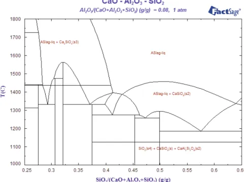
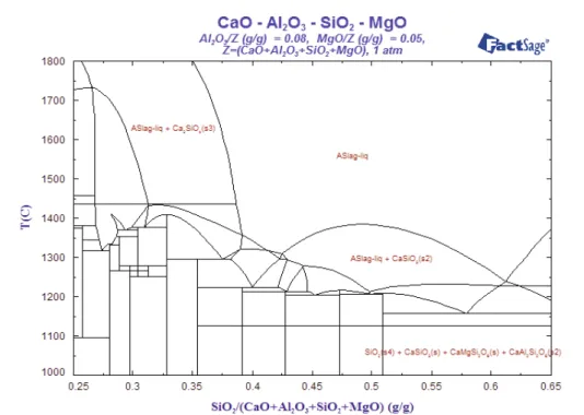
For treating LF slag in a separate ladle, it has to wait for casting to be over and it requires around 50-60 min (as per plant data of TSL Jamshedpur) to complete. By the time the slag will lose considerable amount of heat. Also, higher amount of silica source is required (depending upon the SiO2 content) compare to borax addition. Therefore, extra heat source is required to treat the ladle slag. During experimentation, it was observed that the tapping of LF slag from the induction furnace was difficult when the temperature decreases below 1600oC. Using FactSage 6.4 [17] with FToxid database, two phase diagrams were drawn and are presented in Fig. 8 and 9. These diagrams reveal that if we fix the basicity (CaO/SiO2) at 1.2 (corresponding SiO2fraction in the diagram is 0.4), the liquidus temperature is around 1350oC. At 1.7 basicity (corresponding SiO
2fraction in the diagram is 0.31), the diagram clearly reveals very high liquidus temperature. Therefore, from the phase diagram study, one has to play judiciously to choose the basicity for external treatment of slag to prevent crumbling.
Table 5.Composition of steel
Table 6.Composition of slag
Table 7.Boron pickup v.s. B2O3added
C, % Si, % Mn, % P, % S, % N, ppm Fe, %
0.22 0.18 0.8 0.035 0.035 70 bal
CaO, % SiO2, % Al2O3, % MgO, % FeO, % B2O3, %
60 30 5 3 1.8 0.2-1.0
Amount of B2O3added (wt% of slag)
[B] in liquid steel (in ppm)
0.2 0.67
0.4 1.44
0.6 3.26
0.8 4.25
5. Conclusions
Based on the observations and the discussion of the results, the salient points of the present investigation are as follows.
1. Various types of additives like borax and barium carbonate were used to stabilize the β phase. Optimum percentage of various additives to prevent disintegration of studied LF slag is:
a) 0.2% Borax b) 2% BaCO3
2. The optimum basicity of the treated slag was obtained as 1.7, when quartzite was used as a silica source in order to prevent the disintegration of LF slag.
3. Using different silica sources, like silica sand, copper slag and fly ash, confirm that the LF slag does not crumble at 1.7 basicity.
4. TCLP results indicate indicates that the barium carbonates treated slag cannot be used for LF slag treatment as barium level is above the permissible limit.
5. Thermodynamic calculation suggests that use of 0.2% addition of borax does not affect the steel quality in terms of boron level. Therefore, borax can be used as additive in the ladle furnace. 6. Decreasing basicity of LF slag by adding silica
can be carried out both in the ladle furnace (after desulfurisation) as well as outside the ladle furnace using external heat source.
7. Treated slag can be used as a replacement for
natural rock for road construction purpose as compressive strength of treated LF slag is high.
Acknowledgement
The authors are thankfully acknowledge the financial assistance offered by M/S Tata steel, Jamshedpur to carry out this investigation and they wish to express their sincere gratitude to Management of Tata steel and CSIR-NML, Jamshedpur for their encouragement to carry out this project work.
References
[1] A. Seki, Y. Aso, M. Okubo, F. Sudo, K. Ishizaka, Kawasaki Steel Tachnical Report, 18(1) (1986) 20-24. [2] J. Eriksson, B. Bjorkman, VII International Conference
on Molten slags, fluxes & salts, the South African Institute of Mining and Metallurgy, Johannesburg, (2004) p. 455-459.
[3] C. Mapelli, M. Guzzon, F. Memolii, M. Marcozzi, Review de Metallurgy, 104(4) (2007) 171-178. [4] D. Durinck, S. Arnout, G. Mertens, E. Boydens, P.T.
Jones, J. Elsen, B. Blanpain, P. Wollants, Journal of the American Ceramic Society, 91(2) (2008) 548–54. [5] S. Kitamura, N. Maruoka, First International Slag
Velorisation Symposium, 6-7 April, Leuven, Belgium, 2009, p. 93-100.
[6] Y. Pontikes, P.T. Jones, D. Geysen, B. Blanpain, Archives of Metallurgy and Materials, 55 (4) (2010) 1167-1172 .
[7] Y. Pontikes, L. Kriskova, X. Wang, D. Geysen, S. Arnout, E. Nagels, O. Cizer, T.V. Gerven, J. Elsen, M. Guo, P.T. Jones, B. Blanpain, 2nd International slag valorization symposium, Leuven, Belgium 18-20 April, 2011, p. 313-326.
[8] F. Han, Q.B. Yang, L. Wu, S. Guo, Advanced Materials Research, 418-420 (2012) 1657-1667 .
[9] W. Gutt, A.D. Russel, Journal of Material Science, 12(9) (1972) 1869-1878.
[10] T.W. Parker, J.F. Ryder, Journal of the Iron and Steel Institute, 146 (1942) 21–61.
[11] G. Harada, T. Yen, M. Tomari, Process for treating molten steel slag with red mud from aluminium industry, US Patent Appl. No - 873329.
[12] C.J. Chan, W.M. Kriven, J.F. Young, Journal of the American Ceramic Society 75(6) (1992) 1621–1627. [13] N. Sakamoto, Current Advance in Materials and
Processes, 9 (4) (1996) 803.
[14] N. Sakamoto, Current Advance in Materials and Processes, 13 (4) (2000) 862.
[15] N. Sakamoto, Current Advance in Materials and Processes, 14 (4) (2001) 939.
[16] Q. Yang, B. Haase, F. Engstrom,; B. Bjorkman. https://www.diva-portal.org/smash/get/diva2:1004258/ FULLTEXT01.pdf (dated 19.12.2016)
[17] FactSage 6.4, www.factsage.com