139 DOI: 10.21279/1454-864X-16-I1-023
© 2015. This work is licensed under the Creative Commons Attribution-Noncommercial-Share Alike 4.0 License.
ABOUT THE MAINTENANCE OF THE HEAT FLOW EXCHANGERS FROM
ENERGETICALLY NAVAL SYSTEMS
Levent ALI1
Ion-Adrian GIRBA2
Anastase PRUIU 3
Daniel MARASESCU 4
1PhD attendee Eng.,Military Tehnical Academy 2PhD attendee Eng.,Military Tehnical Academy
3Professor PhD Eng., Marine Engineering and Naval WeaponsDepartament 4PhD attendee Eng., Marine Engineering and Naval WeaponsDepartament
Abstract: The paper presents the main activities of maintenance that ensures the operating characteristics of the fluid used to transfer energz flows. Through their adequate treatment and maintain quality exchangersurfaces energy flows through periodic cleaning with or without disassembly.
Keywords:heat exchanger, fouling, overall heat exceanger temperature, corrosion.
INTRODUCTION
Flux exchangers of thermal energy are devices that allow the transfer of heat between two or more fluids having different temperatures. Flux exchangers of thermal energy have an important role in extraction of flux of thermal energy produced by a mechanism in operation to keep the temperature of the equipment. Also needed to enhance the ability of heat exchange, which is reduced after a period of operation without interfering with maintenance operations.
Marine energy systems, flux exchangers of thermal energy are found as steam generators, water heaters, preheaters and coolers (condensers) and evaporators used in installations for producing technical water from seawater. Flux exchangers of thermal energy can take place with or without changing their state of aggregation, which influences the design of the exchangers. Thus according to the state of aggregation of fluids in flux exchangers of thermal energy used in marine energy plants, this can be divided into:
- heat exchanger that performs heat exchange without changing the fluids state of aggregation like coolers and heaters;
- heat exchanger that performs heat exchange with changing the state of aggregation one of fluids or all like evaporators and condensers.
From the point of view of the geometrical configuration, the heat exchangers can be:
- tubular heat exchangers whose construction consists of a large diameter tube through which to be circulated the fluid to remove the heat, in which is inserted a number of pipes through which circulates the fluid gives off heat (figure1);
- plate heat exchangers whose construction consists of several sets of plates which are in firm contact each with other. Figure 2 illustrates a plate heat exchanger with all components. In one plate is moving the fluid which give up heat, and through the two adjacent plates have to take the circulating fluid heat (cooling agent).
- fluids circuit the plate heat exchangers fluids circuit is shown and explained in figure 3.
140 DOI: 10.21279/1454-864X-16-I1-023
© 2015. This work is licensed under the Creative Commons Attribution-Noncommercial-Share Alike 4.0 License.
Figure 2 – Plate heat exchanger [7]
Figure 3-Fluids circuit through a plate heat exchanger [9]
Another type of heat exchanger used in marine energy systems represents are in spiral. (figure 4a). These heat exchangers are constructed of concentric pipes so that the flow of fluids is concentric, creating a vortex flow of liquids which increase the heat transfer efficiency. Another advantage is the low maintenance costs compared to other types of heat exchangers of the same size. Swirl flow is a flow rotating (figure 4b) which has the property of cleaning fouling inside the exchanger.
a)
b)
Figure 4 – Spiral Heat Exchanger [8]
THE OVERALL HEAT TRANSFER COEFFICIENT
The heat transfer rate of a heat exchanger it is expressed by the formula (1).
[kW] (1), where:
–heat transfer rate [kW];
U – overall heat transfer coefficient [kW/m20C];
A – flux exchanger of thermal energy area [m2];
- the average logarithmic of temperature difference between the fluids [0C].
The determining factor of heat transfer rate is the overall heat transfer coefficient which represents total resistance to heat transfer to a fluid flow to another depending on the flow geometry, fluid properties and composition of the material.
One of equations that can be used to calculate the overall heat transfer coefficient is the relationship (2).
(2), where:
h – heat transfer coefficient by convection
;
L – the wall thickness ;
λ – thermal conductivity ;
So the efficiency of a heat exchanger is given by the thermal conductivity of the material from which it is made and its geometric configuration.
141 DOI: 10.21279/1454-864X-16-I1-023
© 2015. This work is licensed under the Creative Commons Attribution-Noncommercial-Share Alike 4.0 License. often used when calculating heat transfer between
a fluid and a solid.
The average difference in temperature between the fluids is a function between flow geometry and properties of the fluid.
When designing heat exchangers are taken into account all these aspects.
Table1 - Typical values of flux of thermic energy transfer coefficients [6]
Flow type [kW/m20 C]
Forced convection; boiling water in a pipe
50
Forced convection; boiling water and liquids a pipe
0,05-10
Air 0,01-0.1
Boiling water 3-100
Condensing water vapor 0,005-1 Gas flow on tubes and between
tubes
0,01-0,35
Hot fluid Cold fluid [kW/m20 C]
Steam Air
0,017539-0,035078
Steam Water
0,4388-1,315
Steam Gases
0,008769-0,08769 Dowtherm Heavy Oils
0,0140-0,105
Table 2 - Evaporators Typical values of flux of thermic energy transfer coefficients [6] Hot fluid Cold fluid [kW/m20 C] Steam Water O,6138-1,315 Steam Organic
Solvents
0,17539-0,3508 Steam Light Oils 0,140-0,3157 Steam Heavy
oils(vacuum)
0,0438-0,1315 Water Refrigerant 0,1315-0,263
Table 3 - Coolers (no phase change) Typical values of flux of thermic energy transfer
coefficients [6]
Cold fluid Hot fluid [kW/m20 C] Water Water 0,263-0,526
Water Gases
0,00548-0,0877 Water Light Oils 0,1052-0,281 Water Heavy Oils
0,01753-0,0877
Table 4 - Condensers Typical values of flux of thermic energy transfer coefficients [6] Cold Fluid Hot Fluid [kW/m20 C] Water Steam
(pressure)
0,6138-1,315
Water Steam (vacuum)
0,526-1,0523
MAINTENANCE OF NAVAL HEAT EXCHANGERS
The coolant used is providing from the environment where the system works. For naval heat exchangers the coolant used in most cases, it is seawater, but is also used technical water (freshwater), oil and air. Using seawater, being an inexhaustible source of cooling, corrosion and scale deposits are common effects that modify the functional parameters of marine heat exchangers. Maintenance of marine heat exchangers is therefore necessary at regular intervals of time to prevent reduction of heat transfer or failure of equipment. Depending on the type of heat exchangers and on the type of fouling, various maintenance methods are used as the final the heat transfer surfaces must be cleaned to prevent any blocking of the flow process.
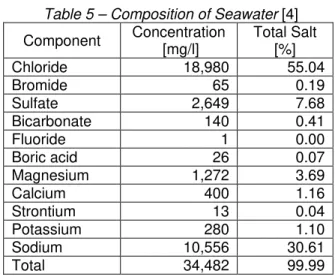
I. Technical water quality (in most cases seawater ) is essential for optimum performance and long serviceable life of heat exchangers. The chemical composition of water is very important for optimal heat exchange. For seawater the fouling effects of salt deposits are directly proportional to its salinity. The salinity of seawater globally has variations of dissolved solids in the liquid at 800 ppm (mg / l) in the Baltic Sea up to a maximum of 60,000 ppm in the Arabian Gulf, where due to water evaporation due to high temperature air desert area. The nominal composition is considered to 34,500 ppm water from which the 25,000 ppm sodium chloride. In
Table 5 is shown the seawater composition.
Table 5 – Composition of Seawater [4]
Component Concentration [mg/l]
Total Salt [%]
Chloride 18,980 55.04
Bromide 65 0.19
Sulfate 2,649 7.68
Bicarbonate 140 0.41
Fluoride 1 0.00
Boric acid 26 0.07
Magnesium 1,272 3.69
Calcium 400 1.16
Strontium 13 0.04
Potassium 280 1.10
Sodium 10,556 30.61
Total 34,482 99.99
142 DOI: 10.21279/1454-864X-16-I1-023
© 2015. This work is licensed under the Creative Commons Attribution-Noncommercial-Share Alike 4.0 License. and all oxides of carbon quivalents . Salinity is
usual measured by determining of the conductivity or of the chlorine content.
II. Fouling of naval heat exchangers is relatively a complex process that is to be taken into account at their design and use.
Fouling in heat exchangers by circulating seawater is of several types:
- crystallization fouling, Crystallization fouling, consisting in deposits of calcium carbonate, calcium sulfate and other salts whose solubility decreases with increasing temperature. This phenomenon generates the deposition of salts on the surfaces of heat exchanger pipes;
- corrosion fouling, is caused by oxidation of the metal layers resulting in the deposition of oxides on the tubes of the heat exchangers;
- Biological fouling, produced by marine
microorganism that grows inside the exchangers forming bacteria or algae deposits, such as mussels and leeches or macro. A special case occurs in the Black Sea water, which in hydrological point of view is a remnant of Sarmatian Sea, with a number of unique aspects in the world including the salinity with averages of 16 ÷ 18 grams of salt per liter instead of 34 ÷ 37 grams per liter in other seas and oceans. This salinity has allowed the development of a very rich microorganism fauna entering the heat exchangers and grows in an accelerated way compared with macro organisms in other seas and oceans, producing biological fouling.
- Particulate fouling that represents the content of sand, silt, mud or other fine particles.
Most problems arise from corrosion fouling and from biological fouling.
Predominant factors in the occurrence of fouling are:
- Surface temperature, Chart in figure 5 is the evolution of coefficient corrosion Rf in function of temperature at constant speed of movement of water for each type of fouling.
Figure 5 - Effect of temperature on various fouling mechanisms at constant velocity [5, pg.14]
- Average temperature of the mass of the fluid is important for biological fouling because when the temperature increase microorganisms grow faster. Also at high temperatures between 85 ÷ 1200C organisms may be killed, but it is not possible because of differences in thermal expansion;
- Water speed (figure 6) generates little effect on crystallization fouling at low speeds and at high speeds may decrease. At low speeds of water the biological fouling rises, and with increasing speed drops to zero because the nutrients supply is no longer assured. In the compact plate heat exchangers the flow rates are much lower than in the tubular heat exchangers.
Figure 6 - Effect of water velocity on various fouling
mechanisms at constant temperature [5, pg.14]
- The concentration of oxygen is an important factor in the occurrence of corrosion fouling. At high temperatures the effect diminishes.
- The materials they are made of heat exchangers have an important role in the development of fouling. Copper alloys containing about 60 ÷ 70% slows development of biological fouling. Ferrous materials are prone to corrosion fouling. Titanium is corrosion resistant material without limits at the seawater temperature, but is sensitive to biological fouling at low speeds. Cathodic protection can increase the maximum operating temperature in seawater. Table 5 gives the values of the thermal conductivity of the materials used for the manufacture of heat exchangers.
Table 6 - The thermal conductivity λ [W/mK] of the various materials at 100 ° C [11]
70/10 copper nickel 35
90-10 copper nickel 52
aluminum 208
aluminum brass 100
copper 389
nickel 200 66
stainless steel (316) 17
143 DOI: 10.21279/1454-864X-16-I1-023
© 2015. This work is licensed under the Creative Commons Attribution-Noncommercial-Share Alike 4.0 License. III. Heat exchanger cleaning is a maintenance
process that is carried out periodically. Cleaning is performed to remove the fouling effects and it can be made by mechanical cleaning or chemical cleaning.
Mechanical cleaning is performed after
exchangers was decommissioned and dismantled from the plant. Descaling is done either manually by brushing fine or blasting steam or hydraulis with pressurized water at pressure up to 600 bar. Most mechanical cleaning methods it is not eliminate only fouling deposits, in most cases the protective layers are removed too.
Chemical cleaning has some advantages over
mechanical cleaning:
- it is faster, the operation lasted one day maximum;
- cleaned surfaces will not suffer mechanical damage;
- chemical solutions reach areas inaccessible to mechanical cleaning;
- it requires fewer hours of physical labor to chenical cleaning;
- cleaning can be done without removing the heat exchangers.
The disadvantage is that at the mechanical cleaning the efficiency of the cleaning can not be confirmed visually becouse the exchanger is completely closed (mounted).
In order to be possible to cleaned , heat exchangers are provided with design facilities like:
- sensors that signal the need for cleaning;
- points for draining results fluids after cleaning chemical;
- access for mechanical cleaning of pipes.
Hydrochloric acid not be used in cleaning heat exchangers with stainless steel plates . Also the water with content greater than 300 ppm Cl is not used in the preparation of cleaning solutions. It is important that aluminum bars and pipes are protected against chemical corrosion.
For cleaning by biological fouling of heat exchangers use alkaline cleaning agents such as sodium hydroxide or sodium carbonate. Cleaning effect can be considerably increased by the addition of small quantities of hypochlorite or agents for the formation of complexes and surfactants. Particular attention should be paid to the exchangers gaskets. Thus the maximum concentration of the cleaning solution shoud be up 4% and the solution temperature does not exceed 80 0C.
At crystallization fouling, where the deposits are of calcium carbonate , calcium sulphate and silicates, are used for cleaning solutions of nitric acid , phosphoric acid, sodium polyphosphates,
complexing agents (EDTA, NTA), sulfuric acid, citric acid. In this case, to protect the gaskets the concentration of the solution should not be greater than 4% and its temperature should not exceed 60 0C. Chemical cleaning of particulate fouling deposits, solutions are used in concentrations up to 4% at temperatures up to 60 0C to protect gaskets. The substances used are: nitric acid, sulfamic acid, sodium polyphosphates, citric acid, complexing agents (EDTA, NTA), phosphoric acid For cleaning of residue deposits of oil, bitumen and grease removal is done by brushing gently and a PARAFFINIC or NAPHTA-BASED solvent (e.g. KEROSINE). Particular attention should be paid to the rubber gaskets that swell on contact with these substances. The solvents Ketones
(acetone, methyletylketone, methuylisobutylketone), Esters (Ethylacetate,
Butylacetate), Halogenated hydrocarbons (Chloro-thene, Carbon tetrachloride, Frenons) Aromatics (Benzene, Toluene) should not be used.. Finally dry with a cloth or rinse with water.
IV. Steam boilers and Exhaust Gas Economizer(EGE)
These are flux exchangers of thermal energy which take heat from marine fuels burned and gives a fresh water that turns into steam or hot water.
Given that usually exhaust temperature of combustion marine engines is between 200 ÷ 300 0C, it is possible heat recovery from the gas by
using Exhaust Gas Economizer. Usually the minimum gas temperature at the exit of the EGE is at least 200 0C, so that the sulfur oxides in combustion products do not condense on the heat exchanger surfaces and cause corrosion thereof. When using a type LPG fuel or gas oil should be reconsidered heat recovery mode because the flue gas temperature can be well below 200 0C.
144 DOI: 10.21279/1454-864X-16-I1-023
© 2015. This work is licensed under the Creative Commons Attribution-Noncommercial-Share Alike 4.0 License.
Figure 7 -Steam flow diagram for an exhaust gas boiler and two oil-fired[12]
A-Economizer section of the Waste Heat
Recovery Boiler; B-Evaporator section of the Waste Heat Recovery Boiler; C- Superheater section of the Waste Heat Recovery Boiler; D -Heat exchanger; E-Condenser; F-Condensate pump; G-Cooling water pump; H-Make-up water pump; I-Boiler feed-water pump; J-Boiler water circulation pump;K-Alternator; 1-Steam pressure control; 2-Water level control; 3-Economizer inlet
temperature control; 4-Condenser pressure
control; 5-Condenser level control; 6-Steam dump control valve; 7-Feed water tank level control.
The efficiency of boiler systems is affected by these issues:
- Stack Temperature Control should be as low as possible, but it should not be low that water vapor in the exhaust condenses on the stack walls. If it used fuels containing significant sulfides, stack temperature should be greater than 200°C to prevent formation of sulphur dew point corrosion. In figure 8 it can see the evolution of sulfuric acid dew point, reported that the sulfur content of fuel.
- Feed Water Preheating using Economizers – the potential for thermal energy saving depends on the type of boiler installed and the fuel used. For example in case of a typically older model shell boiler, if gas exit temperature is 260 0C, an economizer could be used to reduce it to 200 0C, increasing the feed water temperature by 15 0C.
Figure 8 - Sulphuric acid dew point of exhaust gas shown as a function of the sulphure
content in the fuel [1]
The overall thermal efficiency is higher by 3%. In case of a modern 3-pass shell boiler firing natural gas with a flue gas exit temperature of 140 0C a condensing economizer would reduce the exit temperature to 65 0C increasing thermal efficiency by 5%;
- Combustion air preheating – improve thermal efficiency by 1% if the combustion air temperature is raised by 20 0C;
- Incomplete combustion – can arise from a surplus of fuel or poor distribution of fuel usually because of incorrect functioning of burners, or insufficient air supply, resulting in a poor mixture in air or fuel;
- Excess air control - is required in all practical cases to ensure complete combustion. When the sum of the losses due to incomplete combustion and loss due to heat in flue gases is minimized, the excess air level is optimum for maximum boiler efficiency.
- Radiation and Convection Heat Loss
Minimization – at the modern boiler design the lose heat of the surface of boiler may represent only 1.5% on the gross calorific value at full rating, but if the boiler operates at 25% and less the lose heat will increase at 6%. The augmentations of isulation reduce the heat loss.
- Automatic Blowdown Control – installed of automatic blowdown control witch respond to boiler water conductivity and pH, because uncontrolled continuous blowdown is is a loss of thermal efficiency.
- Reduction of Scaling and Soot Losses –
145 DOI: 10.21279/1454-864X-16-I1-023
© 2015. This work is licensed under the Creative Commons Attribution-Noncommercial-Share Alike 4.0 License. stack temperature up 22 ° C leads to a loss
inefficiency of 1%. It is estimated that 3 mm of soot can cause an increase in fuel consumption by 2.5% due to increased flue gas temperatures. Periodic off-line cleaning of radiant furnace surfaces, boiler tube banks, economizers and air heaters may be necessary to remove stubborn deposits.
Another aspect is the accidental burning of the soot deposits after diesel engine is a growing problem. To alert temperature increases boilers are equipped with temperture sensors or even a static pressure dropalarm. But this are just alarms. To ovoid accidental burning of the soot deposits, modern ships are equipped with boiler monitoring system. An example of such equipment is manufactured by Green Instrumentas in Denmark, G5100 Exhaust Gas
Economizer Monitor (figure 9), which are
accepted by ship classification societies such as Bureau Veritas in this case. This monitoring system provide a dynamic monitoring of different parameters in relation to engine load including pressure drop, inlet and outlet temperature and the water circulation flow.
Figure 9 – Diagram of G5100 Exhaust Gas Economizer Monitoring by Green Instrumentas,
Denmark [2]
Monitoring these parameters along with actual engine load will indicate soot contamination and the best time for cleaning, thus helping to maintain high
efficiency of the economizer and ovoid economizer breakdown.
The system consists of the following main elements:
- monitoring cabinet with touch screen ( 4 alarm relays and 2 analog inputs;
- remote input module with 4 analog inputs; - differential pressure transmitter unit; - temperature sensor;
- flow sensor.
CONCLUSIONS
Variety of sources that may cause fouling deposits on heat exchangers surfaces resulted in a very complex approach in terms of design, construction, operation and maintenance of these.
Since the deposition of fouling in heat exchangers impedes the flow of heat exchange, it requires careful planning of maintenance operations that will take into account the synergy of the chemical mechanical cleaning depending on the type of fouling.
Any phenomenon that affects the efficiency of heat exchangers has direct effects on the global heat transfer coefficient which ultimately leads to reducing the rate of heat transfer.
The heat exchangers materials must have thermal conductivity, resistance to interaction with fluids to circulate through them at speeds and temperatures working fluid as required installation that will work.
Modern systems for monitoring heat exchangers in service increase their life time by continuously monitoring the functional parameters and indicating the best time for maintenance operations.
BIBLIOGRAPHY:
[1] MAN B&W Diesel A/S, Copenhagen, Denmark, „Soot Deposit and Fire Exhaust gas Boiler”, Engineering the Future –Since1758,
146 DOI: 10.21279/1454-864X-16-I1-023
© 2015. This work is licensed under the Creative Commons Attribution-Noncommercial-Share Alike 4.0 License. [ 2] Green Instrumentas, Denmark, G5000 Boiler Dynamic Multi-Parameter Monitoring-Monitoring,
www.greeninstruments.com ;
[ 3] „Pacific Marine & Industrial- Shell and Tube Heat Exchangers,
http://www.pacificmarine.net/engineering/heat-exchangers/shell-and-tube-heat-exchangers.htm; [ 4] Performance Of Tubular Alloy Heat Exchangers In Seawater Service In The Chemical Process Industries, Publish by Materials Tehnology Institute of the Chemical Proces Industries, Inc. and Nickel Development Institute,
https://www.nickelinstitute.org/~/media/Files/TechnicalLiterature/PerformanceofTubularAlloyHeatExchangers inSeawaterServiceintheChemicalProcessIndustries_12002_.ashx;
[ 5] S. Pugh, G.F.Hewitt, H. Muller-Steinhangen“Fouling During the Use of Seawater as Coolant - The Development of a `User Guide' ”, Engineering Conferences International Year 2003;
http://dc.engconfintl.org/cgi/viewcontent.cgi?article=1001&context=heatexchanger; [ 6] http://www.enginersedge.com/heat_transfer-cofficients ;
[ 7] http://www.jialong-coolers.com/oil-to-water-heat-exchanger/21298460.html;
[ 8] http://www.marineinsight.com/refrigeration-air-conditioning/types-of-heat-exchangers-on-a-ship/; [9]http://www.plateheatexchanger.org/brazed-heat-exchanger/General-Information/The-Structure-of-Plate-Heat-Exchanger ;
[10] https://ro.wikipedia.org/wiki/Marea_Neagră;
![Figure 3-Fluids circuit through a plate heat exchanger [9]](https://thumb-eu.123doks.com/thumbv2/123dok_br/18162714.328979/2.893.89.416.121.608/figure-fluids-circuit-plate-heat-exchanger.webp)
![Figure 5 - Effect of temperature on various fouling mechanisms at constant velocity [5, pg.14]](https://thumb-eu.123doks.com/thumbv2/123dok_br/18162714.328979/4.893.471.810.381.593/figure-effect-temperature-various-fouling-mechanisms-constant-velocity.webp)
![Figure 7 - Steam flow diagram for an exhaust gas boiler and two oil-fired[12]](https://thumb-eu.123doks.com/thumbv2/123dok_br/18162714.328979/6.893.468.808.121.394/figure-steam-flow-diagram-exhaust-gas-boiler-fired.webp)

