MOHAMMAD NEZAMINIA*, SALIM ABID TABASSUM**, AND IJAZ AHMAD CHAUDHRY*** RECEIVED ON 11.03.2012 ACCEPTED ON 18.09.2012
ABSTRACT
In this article a novel breed of snake-like climber robots has been introduced. Structure and operation of the first generation of snake-like climber robot "Marak I" has been discussed. The gait planning for two dimensional locomotion of a novel snake-like climber robot "Marak I" is presented. The types of locomotion investigated were rectilinear and wheeling gaits. The gaits of locomotion were experimented and their suitability for various applications has been mentioned. Some encountered practical problems plus solutions were addressed. Finally we found out that: the vertical motion was producing more fault than horizontal locomotion, and notably the fastest gait of locomotion was the wheeling gait.
Key Words: Snake-Like Robot, Climber Robots, Rectilinear Gait, Wheeling Gait, Gait Planning.
* Ph.D. Scholar, Department of Mechatronics & Control Engineering, University of Engineering & Technology, Lahore. * * Professor, Department of Mechanical Engineering, University of Engineering & Technology, Lahore.
*** Professor, Department of Mechatronics & Control Engineering,University of Engineering & Technology, Lahore.
1.
INTRODUCTION
of snake-like climber robots. There are several advantages linked to snake-like robots including, high stability, high terrain ability, high versatility and maneuverability of motion, high redundancy, high reliability, small cross-sectional size, and ease of sealing to name a few. Most of the snake-like robots built to date have a modular design. This modularity gives them higher precedence in the fields
of maintenance, assembly and service than most of the conventional robots. Due to the mentioned advantages the snake-like robots can perform several tasks better than any other robot. This property will let them to be applicable in several areas such as: search and rescue (earthquake), surgery (minimally invasive surgery, laparoscopes and endoscopes), exploration, inspection (for hard-to-reach areas, cables, pipes and hazardous environments),
T
he snake-like robots, can be defined and interpreted in different ways. Our definition of snake-like robots, with small variation, comes from Hirose, et. al. [1] description as those mobile robots that are made of abundant serially connected articulated portions, are inspired by snakes, and imitate one or several characteristics of snakes in nature. For example they mayfirefighting, reconnaissance (military, police), espionage, stealth operation, and assembly to name a few. The snake-like robots that mimic the locomotion pattern of snakes can demonstrate one or several natural gaits of locomotion, which include lateral undulation, concertina, rectilinear,
and sidewinding gaits. However, some of them are capable of undergoing non- snake gaits of locomotion as well. For example the wheeling, screwing, lateral rolling, wave rotor traveling, and flapping locomotion gaits are among the non-snake gaits of locomotion. Some other non-snake gaits are very similar to snake gaits, for example the caterpillar gait in worms is very similar to rectilinear gait. The climber snake-like robots may be capable of showing all the natural gaits of locomotion on horizontal surfaces but when facing the vertical flat terrain, the number of applicable natural gaits of locomotion will reduce. In this work the rectilinear gait (snake gait) and wheeling gait (non-snake gait) of locomotion has been used for both horizontal and vertical terrains. In the upcoming section there would be more explanation on these two gaits. If the work on snake-like robots be traced back, we find Gray, [5] who was the first to perform a real engineering work on snakes by exploring the natural gaits of locomotion through Newtonian laws. After his initial efforts in engineering field, Shigeo Hirose was the first who actually made the first truly snake-like robot (Hirose, [6]). His robot was called the ACM and was based on a model of lateral undulation gait. Later on, different dynamic models were created (e.g. the models of
Liljebäck, et. al. [7] and Kane, et. al. [8]) and different types of snake-like robots were designed and constructed. However most of them were designed for terrestrial locomotion. Some of these snakes were capable of climbing different obstacles.
If we try to generalize, the climbing methodology in all
the prior work can be divided into two categories. The first is the free climbing (Nilsson, [9]) in which the robot
just uses its own joints for climbing. The second type is the anchoring/aid climbing in which the robot uses some
kind of anchoring or support mechanism (For example the robot can use grooves, openings or poles as anchoring mechanism (Goldman, et. al. [10]). Although
there has been so many snake designs that could follow
one or both types of climbing categories (For example the pole climbing robot of Lipkin, et. al. [11]), but, up to
now, there has not been any constructed snake-like climber robot capable of climbing a vertical flat terrain to a point higher than the self-length of the robot. In fact
we believe that we were the first one to construct a
snake-like climber robot [4]. We named the robot "Marak I". It was a robot with planar locomotion capability which
incorporated the active suction cups in its anchoring mechanism. It was the first designed and constructed snake-like climber robot which incorporated these types
of grippers in its anchoring mechanism. Here when we
say snake-like climber robot, we mean a wall climbing robot that follows our definition of snake-like robot. From
this point of view all other wall climbing robots which are not made of abundant serially connected articulated portions, or do not imitate the snakes (Lipkin, et. al. [12],
Granosik, et. al. [13], Lal , et. al. [14]) will get excluded
from our definition.
less practical than our active suction cups. In addition to making the first robot with aforementioned properties, we were the first who examined and implemented the wheeling gait of locomotion for vertical climbing of snake-like robot. Although, Ma, et. al. [18] worked on climbing the slopes with snake-like configuration however he worked on lateral undulation gait. While our work was based on rectilinear as well as wheeling gaits from the snake and non-snake locomotion gait categories. In this paper we investigate the locomotion gait planning for both rectilinear and wheeling gaits.
2.
ROBOT STRUCTURE AND
OPERATION
The "Marak I" and its successor generation "Marak II"
(yet to be constructed) consist of several modules. Each
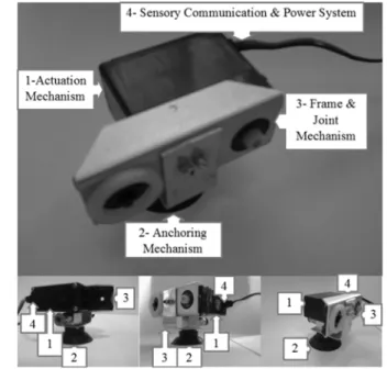
module itself consists of four major parts which are the actuation mechanism, anchoring mechanism, frame and
joint mechanism, and sensory communication and power
system. For "Marak I" the actuation mechanism consisted
of the dc geared motor. Here by actuation mechanism we
mean the dc motor actuation that is responsible for motion of robot's joints (This actuation mechanism is different
from pneumatic actuation mechanism, vacuum actuation
system or suction cup actuation that would be discussed
later in this article). The anchoring mechanism consisted
of a suction cup and its accessories. The frame and joint mechanism consisted of aluminum chassis and support
parts plus the fittings and a bearing. The sensory,
communication and power system consisted of associated
wires and a potentiometer. Fig. 1 shows the major parts of
one module of "Marak I". The modules could be placed in linear or zig-zag configuration. Fig. 2 demonstrates these
two different placement methods. The zig-zag
configuration was preferred because under the available
physical constraints, it provided the minimum link length.
The link length should be kept as minimum as possible. This, on one hand, will reduce the torque exerted on
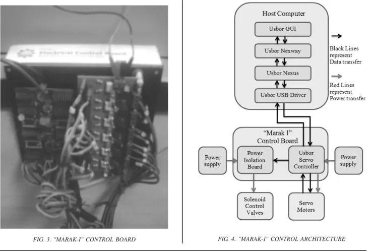
modules and on the other hand is an important factor on mobility increment of the robot in bounded spaces, Dowling, [19]. The "Marak I" was powered through
variable dc power supply. Its motion was controlled by PC
through a Control Board as shown in Fig. 3.
The Control Board consisted of Usbor Servo Controller
and Power Isolation Board. The Usbor Servo Controller is a part of Robix Rascal set (Usbor-321 Rev: 0.0.2 was
FIG. 1. MAJOR PARTS OF A MODULE OF "MARAK-I" ROBOT FROM DIFFERENT POINT OF VIEWS
FIG. 2. MINIMUM POSSIBLE LENGTH FOR ZIG-ZAG AND LINEAR CONFIGURATIONS (TO ACHIEVE ROTATIONAL
used here). It was used for controlling the servo motors and sending on/off signals to Power Isolation Board.
The Power Isolation Board was used to energize solenoid control valves from an optically isolated power supply. The Usbor Control Board was programmed through
Usbor dedicated programming environment. The
programming environment included Usbor Nexway and Nexus programs which ran on Java Runtime Environment.
The environment then sends/receives data through Usbor USB driver. This environment generates a point-to-point trapezoidal velocity trajectory by feeding
different motion commands/parameters to its GUI
(Graphical User Interface) e.g. position, velocity, and acceleration, to name a few. The motion commands are
written in the GUI based on predefined Usbor script format. Fig. 4 demonstrates the robot's control architecture.
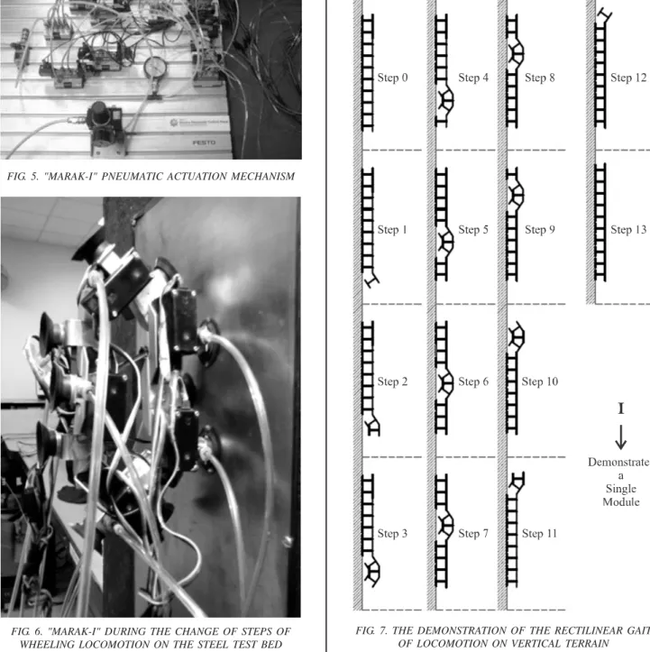
A high pressure jet of air, while passing through ventury,
created vacuum. The vacuum was applied to each module through pipes connected between ventury and the
modules. Between supply and suction cups, the pneumatic
actuation mechanism was implemented (consisting of
directional and solenoid control valves), to connect/ disconnect the vacuum lines (depicted in Fig. 5). With the
help of these supplying, computing, actuating and
communicating units the robot locomotion could be
empowered, programmed and controlled. Fig. 6 shows the
robot under operation between two steps of wheeling gait.
2.1
Model Demonstration
For ease of understanding each module was depicted as
a bold line connected in the middle with series of lines resembling the shape of the inverted T. In fact the
inverted T gives a simple demonstration of the suction cup. This representation gives better insight into the
climbing methodology. Fig. 7 shows this demonstration technique.
2.2
Gait Planning
Although "Marak I" was a two dimensional robot however
several natural and non-natural gaits of locomotion could be implemented on it. Among these the rectilinear,
concertina, inchworming, wheeling, or different combination of these gaits could be implemented. In
FIG. 5. "MARAK-I" PNEUMATIC ACTUATION MECHANISM
FIG. 6. "MARAK-I" DURING THE CHANGE OF STEPS OF WHEELING LOCOMOTION ON THE STEEL TEST BED
between these gaits the rectilinear gait was selected to be the main gait of locomotion due to its high stability and
low terrain slippage trend (Dowling, [19]). The gait was generated simply by passing a half wave from the tail of the robot to its head. When the half wave passes from the
tail to the head, the associated links will be raised and
lowered down accordingly and as a result the robot locomotes forward. The rectilinear gait presented here is
based on the sequential motion representation by Merino, et. al. [20]. Fig. 7 demonstrates the rectilinear gait and its different sequences of motion on vertical terrain.
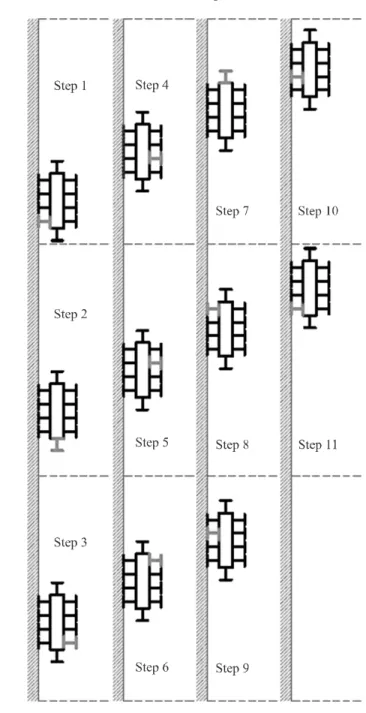
After implementing all the applicable gaits of locomotion on "Marak I" we became interested in the wheeling gait because we found it to be the fastest possible gait on vertical terrain (as a result the same gait is designed to be implemented on "Marak II"). Here in this paper we investigate these two gaits of locomotion. The wheeling gait will be formed if the head and tail of the robot be connected together in such a way that a loop of four distinct parts be made. The first and third parts are going to be equal in length and parallel to each other where the first would lie on the terrain and the third would be away from the terrain. The second and fourth parts are on two sides of the loop. This configuration is shown in Fig. 8. In fact the shape and locomotion of the robot will become similar to the shape and locomotion of a wheel. The wheeling gait was first implemented by Yim, [21-22]. Indeed the wheeling gait presented here is very similar to the Rolling-Track gait proposed by him. For controlling the gait of locomotion the Yim's GCT (Gait Control Table) [21] was used with a minor change. The GCT is a table having the numeric values of absolute rotations of each joint in degrees. The rows show the step number and the columns represent the associated module joint of the robot. In the GCT represented here the modules on each row, from the start to end, are synchronized. They start and stop at the same time. However, in the Yim's GCT the motion will start
at the first segment of the row and ends at the last segment of the row.
The GCTs of the rectilinear and wheeling gait is depicted in Tables 1-2 accordingly. These control gaits have been
considered for implementation with and without the actuation of the suction cups on horizontal terrain and
with the actuation of suction cups on the vertical terrain.
It should be mentioned here that while the observer is faced towards the front view of the servo the plus sign
(+) indicates the clockwise rotation and minus sign (-) shows the counter-clockwise rotation. The servos have been assembled in such a manner that the home position
(zero) of the servos is at the middle of their rotational
domain. By our convention in rectilinear configuration the joints are numbered from the lowest joint, as first, to
the highest joint, as last, on vertical terrain. While on the horizontal terrain the numbering is from the right to the left for moving from right to left and vice versa (for left to
right motion).
TABLE 2. THE WHEELING GAIT OF LOCOMOTION
Step Rotation of Module Number (In Degrees)
Number 1 2 3 4 5 6 7 8 9 1 0
1st Step +90 -90 0 0 0 -90 +90 0 0 0
2nd Step +90 0 0 0 +90 -90 0 0 0 -90
3rd Step 0 0 0 -90 +90 0 0 0 +90 -90
4th Step 0 0 +90 -90 0 0 0 -90 +90 0
5th Step 0 -90 +90 0 0 0 +90 -90 0 0
6th Step +90 -90 0 0 0 -90 +90 0 0 0
7th Step +90 0 0 0 +90 -90 0 0 0 -90
8th Step 0 0 0 -90 +90 0 0 0 +90 -90
9th Step 0 0 +90 -90 0 0 0 -90 +90 0
10th Step 0 -90 +90 0 0 0 +90 -90 0 0
11th Step +90 -90 0 0 0 -90 +90 0 0 0
TABLE 1. THE RECTILINEAR GAIT OF LOCOMOTION
Step Rotation of Module Number (In Degrees)
Number 1 2 3 4 5 6 7 8 9
0th Step 0 0 0 0 0 0 0 0 0
1st Step -35 0 0 0 0 0 0 0 0
2nd Step +35 +35 0 0 0 0 0 0 0
3rd Step +35 -35 -35 0 0 0 0 0 0
4th Step -35 -35 +35 +35 0 0 0 0 0
5th Step 0 +35 +35 -35 -35 0 0 0 0
6th Step 0 0 -35 -35 +35 +35 0 0 0
7th Step 0 0 0 +35 +35 -35 -35 0 0
8th Step 0 0 0 0 -35 -35 +35 +35 0
9th Step 0 0 0 0 0 +35 +35 -35 -35
10th Step 0 0 0 0 0 0 -35 -35 +35
11th Step 0 0 0 0 0 0 0 +35 +35
On the wheeling gait the first joint is situated between
the lowest connected module to the wall, pink module depicted on Fig. 8, and its counter clockwise neighbor. The numberings continues in the counter clockwise
manner. For horizontal wheeling locomotion the first joint for moving right to left would be between the first
module on the right side and its counter clockwise neighbor. For moving from left to right, the vice versa is employed. Although so many configurations were possible with the wheeling gait however by considering
the limitation of rotation on the modules of robot the optimum configuration with respect to detaching
moment arm and deflection of suction cups were achieved under the depicted wheeling configuration of Fig. 8. There are so many possible angular
configurations for rectilinear gait as well however, the angle of 35 degrees was chosen because by going a little bit beyond this angle, in this gait, the suction cups
of the module and its second consecutive module will touch each other. It should be emphasized here that 35 degrees limitation will not occur in wheeling gait.
Because due to the zig-zag shape of the robot, gait design, and our convention of plus/minus sign, the modules are able to go to the mentioned plus or minus
90 degrees in wheeling gait. As it can be seen from Table 2, during each step of the gait just four joint angles are going to vary. If the rest of the joints of the robot be
locked during transition from one step to other a simplified configuration which resembles the four-bar
mechanism will be obtained.
3.
EXPERIMENTATION
For experimentation the "Marak I" was placed on different test beds made of flat surfaced wood, steel,
concrete and glass (mirror). The "Marak I" showed full climbing capability in all of them which proved the
correct design of the robot. However, the best results, as expected, was obtained from the mirror terrain due to
its smoothness characteristics. Both horizontal and vertical locomotions were performed on the aforementioned terrains.
Mainly due to the deflection of the suction cups the
gaits of locomotion could not be followed exactly as
the proposed GCTs. In fact by hit and trial methods the
horizontal locomotion could be performed with a very
minor deviation from GCTs, however the vertical locomotion had considerable deviation from the initial
gaits of locomotion. Another issue which created some
errors was the change of height of robot from
un-actuated to un-actuated suction cup with 3.5 mm difference.
All the associated errors plus the inaccuracy of the potentiometer sensor led the maximum deflection error
of seven degrees. To compensate this problem some of
the servos had to be rotated more. Another issue in
practical experimentation was the bending of some of the suction cup's lips inward in some steps of different
gaits of locomotion. For addressing this problem partial
strengthening of the suction cups were employed.
Although the errors were reduced but they were still
present however the overall performance was fine. By
experimenting the robot three times and each time with three consecutive gaits of locomotion under the same
conditions we found out the average climbing velocity
with single wave rectilinear gait on all testing beds to
be1.06 mm/sec while the average velocity with wheeling
gait was found out to be 10.08 mm/sec which is 9.51 times the rectilinear velocity. Wheeling gait showed the
maximum deflection and was less stable compared to
the rectilinear gait. Although our goal was not to build
profile of servos, low servo power to module weight
ratio, low servo torque to module inertia ratio, pulling force of the pipes and wires connected to the
robot, deflection in suction cups (higher deflection will
require the robot to move more for reaching the same
point while it enforces more stabilization time after every sticking step), low negative pressure (lower pressures
were also possible but not economical), low volume
flow rates (higher volume flow rate were achievable but
not economical), leakage from suction cups, use of
directional control valves plus solenoid control valves instead of direct use of vacuum solenoid valves for
vacuum actuation system, high friction in between
robot parts and low thermal capacity of servos.
4.
CONCLUSION
The "Marak I" was implemented on different terrains
with different gaits of locomotion and showed the full
climbing capability. The gaits of locomotion were
planned and the robot implemented these for traversing
the terrains. The kinematic, static, and dynamic
modeling plus mathematical simulation is presented in
a separate (to be published) paper. By comparing the
results obtained from the experimentation we get to the
following conclusions that: from the stability and
deflection point of view the rectilinear gait showed the
best results. As it was expected, from the speed point
of view the wheeling gait showed maximum speed of
locomotion among all the applicable gaits of locomotion
on "Marak I" with almost 10 times the locomotion speed
of the rectilinear gait. Finally for applications where the
stability is the main concern, the rectilinear gait should
be selected while for the applications where the speed
of locomotion is the main issue, the wheeling gait should
be implemented.
ACKNOWLEDGEMENT
The authors would like to thank the Internal and External
Reviewers of this paper for their reviews, and helps.
REFERENCES
[1] Hirose, S., and Fukushima, E.F., "Snakes and Strings:
New Robotic Components for Rescue Operations",
Proceeding of 41st SICE Annual Conference, Volume 1,
pp. 338-343, Osaka, Japan, 2002.
[2] Liljebäck, P., Fjerdingen, S., Pettersen, K.Y., and Stavdahl,
O., "A Snake Robot Joint Mechanism with a Contact
Force Measurement System", IEEE International
Conference on Robotics and Automation, pp.
3815-3820, Kobe, Japan, 2009.
[3] Ma, S., "Analysis of Snake Movement for Realization
of Snake-Like Robots", Proceeding of IEEE
International Conference On Robotics And Automation,
Volume 4, pp. 3007-3013, Detroit, Michigan, USA,
1999.
[4] Nezaminia, M., "Design and Construction of High
Mobility Articulated Robot "Marak I"", M.E. Thesis,
Department of Mechatronics & Control Engineering,
University of Engineering & Technology, Lahore,
Pakistan, 2008.
[5] Gray, J., "The Mechanism of Locomotion in Snakes",
Journal of Experimental Biology, Volume 23, No. 2, pp.
101-120, Cambridge, UK, 1946.
[6] Hirose, S., "Biologically Inspired Robots: Snake-Like
Locomotors and Manipulators", Oxford University
Press, New York, USA, 1993.
[7] Liljebäck, P., Stavdahl Ø., and Pettersen K.Y., "Modular
Pneumatic Snake Robot: 3D Modelling, Implementation
And Control", Modeling, Identification and Control,
Volume 29, No. 1, pp. 21-28, Norway, 2008.
[8] Kane, T.R., and Levinson D.A., "Locomotion of Snakes:
A Mechanical 'Explanation'", International Journal of
Solids and Structures, Volume 37, No. 41, pp. 5829-837,
[9] Nilsson, N., "Snake Robot-Free Climbing", IEEE Control
Systems, Volume 18, No. 1, pp. 21-26, USA, 1998.
[10] Goldman, G., and Hong, D., "Considerations for Finding
the Optimal Design Parameters for a Novel Pole
Climbing Robot", ASME Proceeding on 32nd
Mechanisms and Robotics Conference, Volume 2, pp.
859-866, New York City, USA, 2008.
[11] Lipkin, K., Brown, I., Peck, A., Choset, H., Rembisz, J.,
Gianfortoni, P., and Naaktgeboren, A., "Differentiable
and Piecewise Differentiable Gaits for Snake Robots",
IEEE/RSJ International Conference on Intelligent
Robots and Systems, pp. 1864-1869, San Diego,
California, USA, 2007.
[12] Briones, L., Bustamante, P., and Serna, M.A.,
"Wall-Climbing Robot for Inspection in Nuclear Power Plants",
IEEE Proceedings on Robotics and Automation, Volume
2, pp. 1409-1414, San Diego, California, USA, 1994.
[13] Granosik, G., and Kaczmarski, M., "Bellows Driven,
Muscle Steered Caterpillar Robot", Climbing and Walking
Robots, Springer, pp. 743-750, Germany, 2006.
[14] Lal Tummala, R., Mukherjee, R., Ning, X., Aslam, D.,
Dulimarta, H., Jizhong, X., Minor, M., and Dang, G.,
"Climbing the Walls [Robots]", IEEE Robotics &
Automation Magazine, Volume 9, No. 4, pp. 10-19,
USA, 2002.
[15] Zhang, H.X., Gómez, J.G., Chen, S.Y., Wang, W., Liu,
R., Li, D., and Zhang, J.W., "A Novel Modular Climbing
Caterpillar Using Low-Frequency Vibrating Passive
Suckers", IEEE/ASME International Conference on
Advanced Intelligent Mechatronics, pp. 1-6, Zurich,
Switzerland, 2007.
[16] Wang, W., Wang, Y., Wang, K., Zhang, H., and Zhang,
J., "Analysis of the Kinematics of Module Climbing
Caterpillar Robots", IEEE/ASME International
Conference on Advanced Intelligent Mechatronics, pp.
84-89, Xi'an, China, 2008.
[17] Li, D.Z., Ma, X.Y., Wang, K., Wang, W., Zhang, H.X.,
and Zong, G.H., "Analysis of Gait Control of
Wall-Climbing Caterpillar Robot", IEEE International
Conference on Robotics and Biomimetics (ROBIO), pp.
1929-1934, Guilin, China, 2009.
[18] Ma, S., and Tadakoro, N., "Analysis of Creeping
Locomotion of a Snake-like Robot on a Slope",
Autonomous Robots, Volume 20, No. 1, Netherlands,
pp. 15-23, 2006.
[19] Dowling, K.J., "Limbless Locomotion: Learning to Crawl
with a Snake Robot", Ph.D. Thesis, Carnegie Mellon
University, Pennsylvania, USA, 1997.
[20] Merino, C.S., and Tosunoglu, S., "Design of a Crawling
Gait for Modular Robot", 17th Florida Conference on
Recent Advances in Robotics, University of Central
Florida, Orlando, Florida, 2004.
[21] Yim, M., "Locomotion with a Unit-Modular
Reconfigurable Robot", Ph.D. Thesis, Stanford
University, California, USA, 1994.
[22] Yim, M., "New Locomotion Gaits", IEEE International
Conference on Robotics and Automation, pp.
2508-2514, San Diego, California, USA, 1994.
[23] Nezaminia, M., Tabassum, S.A., Ghayour, M., Arif, K.M.,
"Dynamic Formulation of Climber Snake-Like Robot",