Modular Pneumatic Snake Robot:
3D Modelling, Implementation And Control
P˚
al Liljeb¨
ack
1Øyvind Stavdahl
2Kristin Y. Pettersen
21Affiliation shared between {SINTEF ICT, Dept. of Applied Cybernetics, N-7465 Trondheim, Norway} and
{Department of Engineering Cybernetics, Norwegian University of Science and Technology, N-7491 Trondheim, Norway}. E-mail: [email protected]
2Department of Engineering Cybernetics, Norwegian University of Science and Technology, N-7491 Trondheim,
Norway. E-mail: {Oyvind.Stavdahl,Kristin.Ytterstad.Pettersen}@itk.ntnu.no
Abstract
This paper gives a treatment of various aspects related to snake locomotion. A mathematical model and a physical implementation of a modular snake robot are presented. A control strategy is also developed, yielding a general expression for different gait patterns. Two forms of locomotion have been simulated with the mathematical model, and experiments with the physical snake robot have been conducted. The simulation results revealed the parameter through which directional control may be achieved for each gait pattern. Experiments with the physical snake robot gave a crude qualitative verification of these findings.∗ Keywords: Snake robot, kinematics, dynamics
1 Introduction
Snake locomotion is a complex and not very efficient form of propulsion. Nevertheless, it represents an in-triguing and promising field of research. Snake locomo-tion is attractive due to its flexibility and the ability of a snake to handle both rough terrain and narrow pas-sages. There are vast applications for both autonomous and remotely operated snake robots. These include ex-ploration and inspection of hostile environments.
Numerous snake robot designs exist. On the other hand, extensive theoretical treatments of snake loco-motion are limited. Mathematical models of snake locomotion that do exist today are mainly concerned with 2D motion. A theoretical and physical treatment of snake locomotion is found in Dowling (1997); Ya-makita et al. (2003); Ohno and Hirose (2001); Saito et al. (2002).
This paper presents a mathematical 3D model for the kinematics and dynamics of a modular snake robot ∗This paper is based on a paper presented at the 16th IFAC
World Congress, 2005.
consisting of 5 segments. A control strategy for the snake robot is proposed and simulations that validate this control strategy are performed. A physical imple-mentation of the snake robot, utilizing a novel principle of actuation, is also presented. Experiments with the physical robot are presented in order to validate the simulation results.
The paper is organized as follows. Section 2 presents the design of the snake robot. Section 3 presents the mathematical model of the snake. Section 4 describes the implemented robot. A control strategy is proposed in Section 5, and the simulation results are presented in Section 6.
2 Design of the snake robot
2.1 Mechanical design
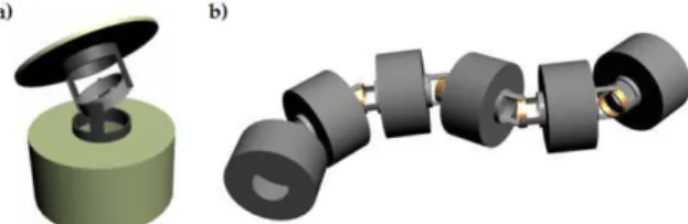
follow-ing. The robot consists of five identical segments with 2 degrees of freedom (DOF) each. A segment is es-sentially an independent module consisting of a hollow cylinder and a plate, connected by a 2 DOF joint. This is shown in Figure 1a. The cylinder contains electron-ics for controlling the segment, while the plate serves as a connection interface to the neighboring segment. The axes of rotation of the 2 DOF in each segment are orthogonal to each other and intersect in the center point between the cylinder and the plate.
A mechanically assembled robot is shown in Fig-ure 1b. Notice the added cylinder in the front of the snake in addition to the five segments. This cylinder represents the head or brain of the snake, and contains electronics dedicated to the high-level control of the movements.
Figure 1: Mechanical design of the snake robot. (a) A segment of the snake consisting of a hol-low cylinder and a plate, connected by a 2 DOF joint. (b) Mechanically assembled snake robot consisting of 5 segments and an extra cylinder in the front, representing the head or brain of the snake robot.
2.2 Principle of actuation
The joints of the robot are actuated by pressurized air. This represents a novel solution to the actuation prob-lem since a majority of previous snake robots utilizes a principle of actuation based on serially mounted elec-tric motors. The main reason for this choice is that pneumatic actuators allow for greater strength in each joint since small-scale electric motors are very limited as to the amount of torque they can produce.
The principle of actuation is illustrated in Figure 2. Each segment utilizes three flexible chambers mounted around the 2 DOF joint. Applying pressurized air to a chamber causes it to expand and move the joint. This assumes that one or two of the other chambers are being depressurized, allowing the movement to take place. The pressurization of each chamber is achieved by small solenoid valves located inside the cylinder in each segment.
Figure 2: The figure shows one of the three chambers that are mounted around each joint. By ap-plying pressurized air to a chamber, it will expand and move the joint.
3 Mathematical modelling
3.1 Kinematics
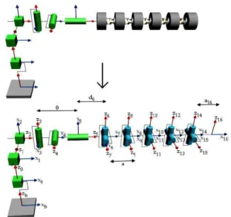
The snake robot is modelled based on the idea that this structure is essentially a robot manipulator. A key dif-ference does exist, however. A conventional robot ma-nipulator will be fixed at one end (base-point), enabling us to relate all positions and velocities of the manipu-lator to this point. A snake robot, on the other hand, is not fixed at any point. This actually adds 6 DOF to the snake, allowing it to translate along 3 axes in space and also rotate around each of these axes. The lack of a fixed base-point is handled by introducing a virtual structure for orientation and position (VSOP). This structure exists purely in theory, and is introduced to cope with the added 6 DOF. The VSOP represents the position and orientation of the snake in an earth-fixed base-frame since one end of the VSOP is earth-fixed and the other end is fixed to the tail of the snake. This is illustrated in Figure 3.
The VSOP consists of 3 prismatic joints represent-ing the position of the tail, and 3 revolute joints repre-senting the orientation of the snake in the base-frame. Note that these joints have no mass, have no moment of inertia, and never exert any forces or torques.
The Denavit-Hartenberg convention, described in Spong and Vidyasagar (1989), is utilized in order to de-rive the kinematics of the whole snake structure (VSOP and snake robot). The variable for jointi, also referred to as the generalized coordinate of joint i, is denoted byqi. Jointi connects linki−1 to link i. The
coor-dinate systems at the bottom of Figure 3 are placed in accordance with the Denavit-Hartenberg convention.
The frames in Figure 3 can be related to each other through coordinate transformations. More precisely, the position and orientation of frameiwith respect to framei−1 is described by the homogeneous transfor-mation matrixAi−1
Figure 3: The degrees of freedom for the snake robot. The earth-fixed VSOP in conjunction with the snake robot is shown at the top. The coordinate systems mounted on the bottom structure have been placed in accordance with the Denavit-Hartenberg convention.
3.2 Dynamics
The dynamic model of the snake robot concerns the relationship between torques and forces acting on the snake and the resulting motion of the snake.
3.2.1 Modelling of external forces
External forces play a vital role in snake locomotion. In order to move forward, a snake utilizes its entire body to create motion patterns that exert forces on the surroundings of the snake. The corresponding counter forces lead to propulsion in the desired di-rection. Ground friction is the most common source for generation of propulsion forces, but a snake may also curve around obstacles in its pathway in order to achieve greater counter forces. This last feature is par-ticularly interesting. In contrast to conventional means of propulsion, where it is desirable to avoid obstruc-tions in the pathway, a snake will rather try to exploit these obstructions. Only friction and normal forces in-duced by contact with the ground are considered in the following.
The contact forces between the robot and the ground are modeled as a mass-spring-damper system. This novel apprach to the modelling of external forces is illustrated in Figure 4. All external forces exerted on a link are applied to the center of gravity (CG) of this link.
Figure 4: Modelling of contact forces between the snake and the ground.
The spring coefficient of the ground,k, must be set to a rather high value in order to mimic the hard-ness of the ground surface. The damping coefficient,
d, serves to damp out oscillating movements induced by the springs. Denote the position of link i in the base-frame by pCGi and the velocity by vCGi. Then,
by extracting the z-components of these two vectors, the normal force on link i in the base-frame may be written
FN,i=
0 ∀pCGi,z≥0
−k·pCGi,z−d·vCGi,z ∀pCGi,z<0.
(1) As pointed out in Saito et al. (2002), biological snakes have a key property related to the ground fric-tion. In particular, the friction in the normal (transver-sal) direction with respect to the snake body tends to be much larger than the friction in the tangential (lon-gitudinal) direction. This property favors propulsion in the forward direction of the snake and reduces side slip-ping. In order to include this property in the modelling of the friction forces, the total friction force is divided into a normal and a tangential part with respect to the snake body. The friction is computed by combin-ing viscous and coulomb friction. Denote the friction coefficient in the tangential and normal direction by
Rt and Rn respectively, and the velocity of link i in
these two directions byvt,CGi andvn,CGi. The friction
force on linki in the tangential and normal direction, respectively, may then be written as
FRt,i=−Rt|FN,i| h
(vt,CGi) T
et i
et, (2)
FRn,i=−Rn|FN,i| h
(vn,CGi) T
en i
en, (3)
whereetanden are unit vectors pointing in the
tan-gential and normal direction with respect to the snake body. All vectors are assumed to be described in the body-frame. The resulting vector of external forces (except for gravity) may now be written as
Fext,i=FRt,i+FRn,i+
0 0 FN,i T
3.2.2 Dynamic model
Using the VSOP perspective and the Newton-Euler for-mulation described in Spong and Vidyasagar (1989), it can be shown that the dynamic model of the robot can be written in the form
M(q) ¨q+C(q,q˙) ˙q+g(q) =τ+τext (5)
where q and τ are the generalized coordinates and forces for the joints of the snake structure (VSOP and snake robot), M(q) is the inertia matrix, C(q,q˙) is the Coriolis and centripetal matrix,g(q) is the vector of gravitational forces and torques, andτextis the
vec-tor of joint forces or vec-torques induced by the external forces on the robot. These vectors and matrices are not detailed here due to their extensive form.
3.3 Simulation setup
The mathematical model of the robot have been im-plemented in Matlab and Simulink in order to simu-late different control strategies and gait patterns. The control strategy for the robot is described in Section 5. A graphical 3D model of the snake and its surround-ings has also been developed. By using the Virtual Reality (VR) toolbox in Matlab, 3D animations of the simulation results are constructed, which facilitate the analysis of these results.
4 Implementation of the snake
robot
A snake robot consisting of 5 segments have been im-plemented in accordance with the design described in Section 2. A mechanically assembled segment without the actuator chambers is shown in 5.
Figure 5: A segment of the snake. (a) Mechanically as-sembled snake segment. (b) Front and back of the electronic circuit boards for the 5 seg-ments.
Figure 5 also shows the front and back of the elec-tronic circuit board mounted inside each segment. Each circuit board comprises a microcontroller ( At-mel ATmega128), pressure sensors for measurements of
chamber pressure, hardware for controlling the cham-ber valves, and hardware for measurements of external forces and joint angles. The implemented snake robot is shown in Fig. 6.
Figure 6: The implemented snake robot.
A PVC fabric is wrapped around the snake body in order to cover up the force sensors mounted along the body. These sensors are so-called force sensing resis-tors (FSR), allowing the snake to respond to external forces.
5 Control strategy
5.1 Motion planning
This section proposes a motion planning algorithm that extends the 2 DOF results presented in Saito et al. (2002) into 3 DOF. Two forms of snake locomotion are considered in conjunction with the motion planning for the snake. These are lateral undulation and sidewind-ing, and are described in more detail in Dowling (1997). Lateral undulation is the most common form of snake locomotion and is achieved by propagating a contin-uous series of waves through the snake body. These waves generate friction forces that enable the snake to push itself forward. Sidewinding is more of a sideways rolling kind of motion and consists of alternating waves of lateral bending.
The following proposes a partitioning of the snake movements into a horizontal and a vertical part. For the 2 DOF joint in segmenti, denote the setpoint for the angle about the vertical and horizontal axis of ro-tation byiq
1,ref andiq2,ref, respectively. A general
iq
1,ref =Ahorsin (ωhort+ (i−1)δhor) +ψhor iq
2,ref =Aversin (ωvert+ (i−1)δver+δ0) +ψver
(6) where i ∈ {1,2,3,4,5} and segment 1 is the fore-most segment. Only the first of these equations are considered in Saito et al. (2002). The first equation relates to the generation of the horizontal wave, and is characterized by the amplitude of the wave Ahor,
the angular frequencyωhor, a phase offsetδhor, and an
angular offset ψhor. The second equation
character-izes the vertical wave in a similar manner, but has an additional parameterδ0 that represents the phase dif-ference between the horizontal and the vertical wave. Different gait patterns are achieved by setting each of these parameters in a particular way.
A conjecture is now given, stating that lateral undu-lation is achieved by setting
Ahor= 30◦, ωhor=
3π
4
rad
/s
δhor=−70◦, ψhor→Direction
Aver = 0◦, ωver = 0rad/s
δver = 0◦, ψver = 0◦, δ0= 0◦
(7)
while sidewinding is achieved by setting
Ahor= 30◦, ωhor= 34π
rad
/s
δhor=−70◦, ψhor= 0◦
Aver = 30◦, ωver=
3π
4
rad
/s
δver =−70◦, ψver = 0◦, δ0→Direction (8)
This conjecture is verified through the simulations described in Section 6. Note how the parameter affect-ing the direction of the locomotion is dependent on the form of locomotion being utilized. When lateral undu-lation is utilized, directional control may be achieved through the parameterψhor, whileδ0 has the greatest influence on the direction during sidewinding.
5.2 Motion control
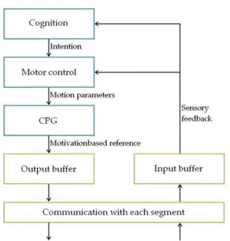
The control strategy developed for the robot is based on abstraction. At the highest level, a motor inten-tion arises. This intention propagates down through the control hierarchy and results in the joints being ac-tuated in a manner that seeks to fulfil this intention. The control hierarchy developed for the brain of the snake is illustrated in Figure 7.
An intention arises in thecognition layer and prop-agates down to the motor control layer. This layer decides the gait pattern that is to be utilized and as-signs values to the parameters characterizing the de-sired motion. These parameters are received by the CPG layer (central pattern generator), which generates
Figure 7: Control scheme developed for the brain of the snake robot.
motivation-based reference set points that are sent to all the segments.
The control scheme taking place locally in each seg-ment is depicted in Figure 8. Motivation-based refer-ence set points from the brain are received and affect the control of the two joint angles. The angular control may also be affected byreflex-basedreference set points induced by contact forces on each segment. Inclusion of reflex-based reference set points enables the robot to curve around external objects in order to achieve greater propulsion forces. The angular control scheme in the outer feedback loop generates joint torque set points to the pressure control scheme in the inner feed-back loop. This scheme controls the pressure in the 3 actuator chambers in accordance with the torque set points, and represents the lowest layer in the control hierarchy.
6 Results and discussion
Figure 8: Control scheme taking place locally in each segment.
6.1 Simulation results
6.1.1 Lateral undulation
This gait pattern is simulated with the parameters given in (7) and with a duration of 65 s. The coef-ficients for the tangential and normal friction were set to
Rt= 0.5, Rn= 3.5 (9)
respectively, thereby simulating a greater friction in the normal direction. In order to validate that direc-tional control may be achieved through variation of the angular offset for the horizontal wave, ψhor, this
parameter is set to vary with time according to (10).
0≤t <15 ⇒ ψhor= 0◦
15≤t <25 ⇒ ψhor= 20◦
25≤t <40 ⇒ ψhor= 0◦
40≤t <50 ⇒ ψhor=−20◦
50≤t <65 ⇒ ψhor= 0◦
(10)
The resulting tail position of the robot in the base-frame is plotted in Figure 9. Screenshots from the 3D visualization of the simulation result are shown in Fig-ure 10. The head of the snake is given a gray color.
The snake moves straight forward along the positive
xb-axis during the first 15 seconds. Subsequently, the
angular offsetψhor is set to 20◦. This triggers a
coun-terclockwise motion. Propulsion straight forward in a new direction continues when ψhor is set back to 0◦
after 25 s. Clockwise motion is produced after 40 s as
ψhor is set to -20◦, thereby changing the direction of
the locomotion once again.
The simulation result shows that lateral undulation is achieved when the motion of the snake is character-ized by (6) and (7).
Figure 9: XY-plot of the tail position of the snake in the base-frame for the simulated gait pattern, lateral undulation.
Figure 10: 3D visualization of the simulated gait pat-tern, lateral undulation. 0 <t<15: Loco-motion straightforward, 15<t<25: Coun-terclockwise motion, 25<t<40: Locomo-tion straightforward, 40 <t <50: Clock-wise motion, 50 < t < 65: Locomotion straightforward.
6.1.2 Sidewinding
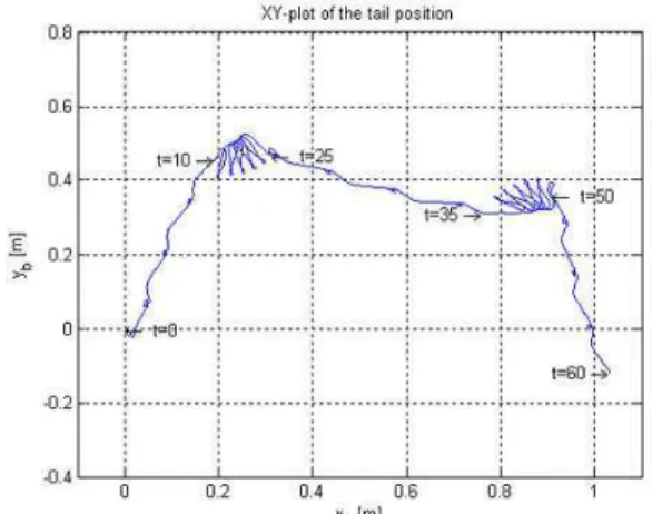
This gait pattern is simulated with the parameters given in (8) and with a duration of 60 s. The coef-ficients for the tangential and normal friction were set as in (9). In order to validate that directional control may be achieved through variation of the phase differ-ence between the horizontal and the vertical wave,δ0, this parameter is set to vary with time according to (11).
0≤t <10 ⇒ δ0= 90◦ 10≤t <25 ⇒ δ0= 0◦ 25≤t <35 ⇒ δ0=−90◦ 35≤t <50 ⇒ δ0= 180◦ 50≤t <60 ⇒ δ0=−90◦
(11)
of the simulation result are shown in Figure 12. The phase difference δ0 is set to 90◦ the first 10 s, during which the snake moves to the left with respect to the direction the head is pointing. After 10 s,δ0is set to 0◦. This produces a counterclockwise rotational motion. Locomotion to the right with respect to the direction the head is pointing is triggered after 25 s, as δ0 is set to -90◦. After 35 s, δ0 is set to 180◦, producing clockwise rotational motion. Finally,δ0 is set back to -90◦, resulting in additional sideways locomotion.
Figure 11: XY-plot of the tail position of the snake in the base-frame for the simulated gait pat-tern, sidewinding.
Figure 12: 3D visualization of the simulated gait pat-tern, sidewinding. 0<t<10: Locomotion to the left, 10 <t <25: Counterclockwise rotational motion, 25<t<35: Locomotion to the right, 35 <t <50: Clockwise rota-tional motion, 50 <t<60: Locomotion to the right.
The simulation result shows that sidewinding is achieved when the motion of the snake is character-ized by (6) and (8). It further shows that sideways locomotion to the left and right with respect to the direction the head is pointing is achieved by setting the phase difference to δ0 = 90◦ and δ0 = −90◦, re-spectively. Counterclockwise and clockwise rotational
motion is achieved by setting the phase difference to
δ0= 0◦ andδ0= 180◦, respectively.
6.2 Experimental results
Experiments have been conducted with the physical robot in order to produce qualitative results that can be related to the simulation results.
6.2.1 Lateral undulation
The physical robot is unable to produce propulsion by lateral undulation. This is partly due to the limited achievable angular velocity in each joint because of the narrow opening of the actuator valves. Another factor is the fact that the snake lack the desirable frictional properties described in Section 3.
6.2.2 Sidewinding
Propulsion by sidewinding is not as dependent on an-gular speed and frictional properties. Hence, the robot is able to achieve propulsion by this gait pattern. Pic-tures of the snake at different time instants are shown in Figure 13. The top row shows a run of 50 s, dur-ing which the phase difference between the horizontal and vertical wave is set to δ0 = −90◦. This yields a sideways motion to the right with respect to the direc-tion the head is pointing. When the phase difference is set toδ0 = 90◦, as shown at the bottom row, loco-motion in the opposite direction is observed. This is in agreement with the simulation results.
Figure 13: Locomotion by sidewinding achieved by the physical robot.
7 Concluding remarks
pat-terns were investigated and the parameters that gov-ern the direction of the propulsion were identified. The hypothesis was validated through simulations of the mathematical model. Observations of the locomotion of the physical robot gave a crude qualitative valida-tion of these results, and confirmed that fricvalida-tion is an important parameter in snake robot locomotion.
Acknowledgments
The authors would like to thank Arvid Lervold, Terje Haugen and Kennet Berg at the engineering workshop at NTNU for their contributions to the implementation of the physical snake robot.
References
Dowling, K. J. Limbless Locomotion. Learning to Crawl with a Snake Robot. Ph.D. thesis, Carnegie Mellon University, 1997.
Ohno, H. and Hirose, S. Design of slim slime robot and its gait of locomotion. InProc. IEEE/RSJ Int. Conf. Intelligent Robots and Systems, volume 2. 2001 pages 707–715.
Saito, M., Fukaya, M., and Iwasaki, T. Serpentine locomotion with robotic snakes. IEEE Contr. Syst. Mag., 2002. 22(1):64–81.
Spong, M. W. and Vidyasagar, M. Robot Dynamics and Control. Wiley & Sons Inc., 1989.