American Journal of Applied Sciences 2 (12): 1574-1577, 2005 ISSN 1546-9239
© 2005 Science Publications
Corresponding Author: S. Rittidech, Faculty of Engineering, Mahasarakham University, Thailand, Tel: +66-43-754316, Fax: +66-43-754316
1574
CPU Cooling of Desktop PC by Closed-end Oscillating Heat-pipe (CEOHP)
S. Rittidech, A. Boonyaem and P. Tipnet
Faculty of Engineering, Mahasarakham University, Thailand
Abstract: The CEOHP cooling module consisted of two main parts, i.e., the aluminum housing and the CEOHP. The house casing was designed to be suitable for CEOHP. The housing to drilling for insert the CEOHP. The CEOHP design employed copper tubes: Two sets of capillary tubes with an inner diameter of 0.002 m, an evaporator length of 0.05 and a condenser length of 0.16 m and each of which has six meandering turns. The evaporator section was embraced in the aluminum housing and attached to the thermal pad of Pentium 4 CPU, model SL 6 PB, 2.26 GHZ. While the condenser section was embraced in the cooling fin housing and cooled by forced convection. R134a was used as the working fluid with filling ratio of 50%. In the experiment, the CPU chip with a power of 58 W was 70°C. Fan speed of 2000 and 4000 rpm. It was found that, if fan speed increases the cooling performance increases. The CEOHP cooling module had better thermal performance than conventional heat sink.
Key words: Closed - end oscillating heat-pipe, CPU cooling, desktop PC
INTRODUCTION
Today’s rapid IT development like internet requires PC performance capable of processing more data more speedily. To meet this requirement, high-performance devices built in PC have been developed. Especially, CPU shows competitive release of more speedy products and a shift toward being more compact and thinner. This leads to higher heat density and increased heat dissipation, making CPU temperature rise and causing the shortened life, malfunction and failure of CPU. Cooling of CPU has been taken seriously. The continuous with a solution to thermal dissipation of desktop PC calls for new technology in CPU cooling. The technology of heat pipe which has been used effectively in CPU cooling of desktop PCs. This study introduces CPU coolers using closed-end oscillating heat pipe (CEOHP). The CEOHP has many advantages, i.e., Large quantities of heat transported through a small cross-section area. The closed-end oscillating heat pipe Fig. 1, is a very effective heat transfer device[1], it has a very simple structure and a fast thermal response. The CEOHP consists of a long capillary tube bent into many turns and the evaporator, adiabatic and condenser section is located at these turns. However, there is no wick structure to return the condensate liquid from the condenser to the evaporator section. Heat is transported from the evaporator section to the condenser section by the pulsation of the working fluid moving in an axial direction in the tube. The inner diameter of the pipe is important. It must be small enough so that under operation conditions liquid slugs and vapor plugs can be formed. If the diameter
is too large, the liquid and vapor inside a tube will become stratified and the operation cannot be established. Rittidech[2] investigated the effect of inclination angles, evaporator lengths and working fluid properties on the heat transfer characteristics of closed-end oscillating heat pipe at normal operating condition, Rittidech et al.[3], studied a correlation to predict heat transfer characteristics of a closed-end oscillating heat pipe at normal operating condition. Zhuang Jun [4], studied a CPU heat pipe cooler. The experimental results, which indicate the loop heat pipe cooling device dissipate heat more efficiently by making use of system fan or case fan. In addition, it saves space and is one of the most promising thermal management solutions for desktop PC. Kwang Soo Kim [5], studied a heat pipe cooling technology for the desktop PC CPU. The heat pipe cooling module had better thermal performance than heat sink. Gi K. et al.[6], studied a CPU cooling of notebook PC by oscillating heat pipe. The experimental results, the oscillating flat type heat pipes establish the high performance cooling system for notebook. Therefore, this study proposes a cooling method capable of reducing unit price, weight and meeting cooling performance requirements. Also, thermal stability of the cooler is tested and accordingly, the cooler to developed and heat sink is compared and analyzed. As the criterion to find the maximum inner diameter of a CEOHPs, Maezawa et al.[7], assumed that where the vapor bubble is formed alternately with the liquid plug within the tube, depended on the properties of the working fluid as:
di ≤ 2(σl/ ρlg) 0.5
Am. J. Applied Sci., 2 (12): 1574-1577, 2005
1575 Fig. 1: Closed-end oscillating heat-pipe (CEOHP)
Fig. 2: Conventional heat sink
Conventional CPU cooling: Conventional CPU cooling show in Fig. 2. The CPU cooling used normally extruded aluminum heat sink showing superiority in terms of unit price, weight and performance. As dissipation has been on the gradual incline and the computer has shifted toward being compact, heat sink has limited cooling performance in the insufficient space. Therefore the application of heat super-conductive CEOHP is considered.
CEOHP kit design-concept and calculation: Some fundamental design parameters e.g. the maximum heat generated by the CPU depending on the PC model. Hence for considering the design of the CEOHP kit, the set and turns of CEOHP have taken into consideration, as well as the CPU chip with a power. From considering designed size of the CEOHP kit, the size and position of the CEOHP kit are designed to take into consideration the fit to area and suitable with CPU temperature.
Fig. 3: Prototype: (a) aluminum base plate (b) copper fin (c) CEOHP
Apparatus design and production:
Prototype: The CEOHP kit for the CPU cooler in Fig. 3, was constructed. The CEOHP kit divided into two parts, i.e. the evaporator is 0.05 m long and a condenser section with the 0.16 m long with and an inclination of 900. The R134a was selected as the working. The filling ratio is 50% of total volume of the tube. The CEOHP kit should transfer at least 70 W of heat power to work properly. And the tube arrangement was aligned in the direction of the CPU chip. The evaporator section was embraced in the aluminum housing of 0.72 m2 and attached to the thermal pad of Pentium 4 CPU, model SL 6 PB, 2.26 GHZ. While the condenser section was embraced in the cooling copper fin housing and cooled by forced convection. R134a was used as the working fluid with filling ratio of 50%. The CPU chip with a power of 58 W was 70°C.
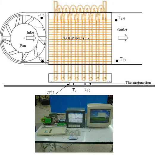
Test rig: This prototype was installed into a test rig, as shown in Fig. 4. The heat coming from the CPU went to the outside aluminum base plate through the CEOHP kit and then transfer to the condenser. The 10 junction point type K thermocouples, installed in different point, the inlet and outlet of the evaporator and condenser section, the under base plate and ambient etc. These thermocouples were connected to a Yokogawa-MX100 acquisition data system. The temperature reading errors of the thermocouples were ±1°C. The run load tested by the Red Alerts program. When the system starts, the temperature of each point was recorded. The reading was taken to interval the chip temperature constant. The thermal performance were determined and compared with the conventional heat sink values.
The thermal performance is obtained by heat dissipated, (Q):
Am. J. Applied Sci., 2 (12): 1574-1577, 2005
1576 Fig. 4: Test rig
Table 1: The results of experiment (conventional heat sink) Fan speed Chip Ambient Rise above Heat (rpm.) temp. temp. ambient temp. dissipated (W)
(0C) (0C) (0C) 2000 37.00 25.30 11.70 4.60
43.00 25.40 17.60 14.0 49.00 25.40 23.60 25.65 50.00 25.50 24.50 25.75 51.00 25.30 25.70 26.79 55.00 25.50 29.50 29.81 55.00 25.50 29.50 29.99 55.00 25.40 29.60 29.99
The controlled parameters were the CPU model of SL 6 PB, 2.26 GHZ, power of 58 W and temperature of 70°C.
The variable parameter was the fan speed of 2000 or 4000 rpm.
RESULTS AND DISCUSSION
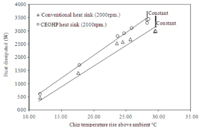
In this experiment, The CEOHP kit had twelve turns, R134a was used as the working, 2 lows and each of which has six meandering turns. The experimental results present the thermal performance of conventional heat sink and CEOHP heat sink on thermal performance (Fig. 5).
Table 2: The results of experiment (CEOHP heat sink)
Fan speed Chip temp. Ambient Rise above Heat dissipated (rpm.) (0C) temp. (0C) ambient(0C) temp.(w) 2000 37.00 25.30 11.70 6.00
43.20 25.40 17.80 17.00 49.10 25.40 23.70 28.00 50.40 25.70 24.70 29.00 51.60 25.70 25.90 31.00 54.00 25.70 28.30 33.00 54.00 25.70 28.30 34.20 54.00 25.50 28.50 34.40 4000 37.00 25.30 11.70 10.00 43.00 25.40 17.60 20.54 49.00 25.40 23.60 33.00 50.00 25.50 24.50 36.00 51.00 25.30 25.70 39.83 53.00 25.50 27.50 43.24 53.00 25.50 27.50 44.37 53.00 25.30 27.70 44.50
Am. J. Applied Sci., 2 (12): 1574-1577, 2005
1577 Fig. 5: Thermal performance of conventional heat sink
and CEOHP heat sink
Fig. 6: Fan speed on the thermal performance of CEOHP heat sink
Thus, the fan speed increases also cooling capacity increases and the thermal performance will be high.
CONCLUSION
In this study, we designed and built an experimental prototype to investigate the thermal performance of a CEOHP heat sink. This unit proved to give reasonable performance, comparable to those obtained by the conventional heat sink cooler. The CEOHP cooling module had better thermal performance than conventional heat sink.
ACKNOWLEDGEMENTS
The research has been supported generously by the Faculty of Engineering, Mahasarakham University. The authors express their sincere appreciation for all of the support provided.
Nomenclature D= diameter, m
G= gravitation acceleration, m s2
m0= air flow rate, kg s1
Q= heat disipated rate, W
Cp= air specific heat at constant pressure, J kg K1
∆
T= difference temperature of air inlet and outlet, °CGreek symbols ρ= density, kg m3
σ = surface tension, N m1
Subscripts i= inner l= liquid
∆T= difference temperature of air inlet and outlet °C
REFERENCES
1. Akachi, H., F. Polasek and P. Stulc, 1996. Pulsating heat pipe. In: Proc. 5thIntl. Heat Pipe Symp., Melbourne, Australia, pp: 208-217.
2. Rittidech, S., P. Terdtoonm, P. Murakamim, P. Kamonpet and W. Jompakdee, 2000. Effect of inclination angles, evaporator section lengths and working fluid properties on heat transfer characteristics of a closed-end oscillating heat pipe. In: Proc. 6th Intl. Heat Pipe Symp., Chiang Mai, Thailand, pp: 413-421.
3. Rittidech, S., P. Terdtoon, M. Murakami, P. Kamonpet and W. Jompakdee, 2003. Correlation to predict heat transfer characteristics of a closed-end oscillating heat pipe at normal operating condition. Appl. Thermal Eng., 23: 497-510.
4. Zhuang, J., 2002. Research on CPU heat pipe coolers. 12th Intl. Heat Pipe Conference. Mosco Russia, Sec., F1-F9.
5. Kwang, S.K., H.M. Won and J.W. Kim, 2002. Heat pipe cooling technology for the desktop PC CPU. 12th Intl. Heat Pipe Conf., Mosco Russia, Sect., F1-F9.
6. Gi, K., and S. Meazawa, 2002. CPU cooling of notebook by oscillating heat pipe. In: Proc. 6th Intl. Heat Pipe Symp., Chiang Mai, Thailand, pp: 166-169.