Ricardo Alves Teixeira
Framework for Media Oriented Transport
Systems
Ricardo Alves Teixeira
F rame w or k for Media Or iented T ranspor t Sys tems
Universidade do Minho
Escola de Engenharia
Dissertação de Mestrado
Ciclo de Estudos Integrados Conducentes ao Grau de Mestre em
Engenharia Electrónica Industrial e Computadores
Trabalho efectuado sob a orientação do
Professor Doutor Adriano José da Conceição
Tavares
Ricardo Alves Teixeira
Framework for Media Oriented Transport
Systems
Universidade do Minho
DECLARAÇÃO
Nome _______________________________________________________________________________________ Endereço electrónico: _______________________________ Telefone: _______________ / _______________ Número do Bilhete de Identidade: ______________________
Título dissertação: _______________________________________________________________________________________ _______________________________________________________________________________________ _______________________________________________________________________________________ Orientador(es): _______________________________________________________________________________________ Ano de conclusão: ___________
Ciclo de Estudos Integrados Conducentes ao Grau de Mestre em Arquitetura
_______________________________________________________________________________________
Nos exemplares das teses de doutoramento ou de mestrado ou de outros trabalhos entregues para prestação de provas públicas nas universidades ou outros estabelecimentos de ensino, e dos quais é obrigatoriamente enviado um exemplar para depósito legal na Biblioteca Nacional e, pelo menos outro para a biblioteca da universidade respectiva, deve constar uma das seguintes declarações:
1. É AUTORIZADA A REPRODUÇÃO INTEGRAL DESTA TESE/TRABALHO APENAS PARA EFEITOS DE INVESTIGAÇÃO, MEDIANTE DECLARAÇÃO ESCRITA DO INTERESSADO, QUE A TAL SE COMPROMETE; 2. É AUTORIZADA A REPRODUÇÃO PARCIAL DESTA TESE/TRABALHO (indicar, caso tal seja necessário, nº máximo de páginas, ilustrações, gráficos, etc.), APENAS PARA EFEITOS DE INVESTIGAÇÃO, , MEDIANTE DECLARAÇÃO ESCRITA DO INTERESSADO, QUE A TAL SE COMPROMETE;
3. DE ACORDO COM A LEGISLAÇÃO EM VIGOR, NÃO É PERMITIDA A REPRODUÇÃO DE QUALQUER PARTE DESTA TESE/TRABALHO
Guimarães, ___/___/______
Media Oriented Transport System
MIEEIC Dissertation
Ricardo Teixeira
Contents
1 Introduction 5
1.1 Document organization . . . 6
2 State of the Art 7 2.1 Controller Area Network . . . 7
2.2 FlexRay . . . 8
2.3 MOST - Media Oriented Systems Transport . . . 8
2.3.1 CAN vs FlexRay vs MOST for multimedia oriented appli-cations . . . 9 2.4 Transmission Paths . . . 10 2.4.1 Optical Fiber . . . 10 2.4.2 Coaxial cable . . . 11 2.4.3 Twisted-Pair cable . . . 11 2.4.4 Conclusions . . . 12
2.5 Node positioning and interconnection . . . 13
2.5.1 Bus Network . . . 14
2.5.2 Star Network . . . 15
2.5.3 Ring Network . . . 16
2.5.4 Mesh Network . . . 18
2.5.5 Conclusions . . . 19
2.6 Electronic Design Automation tools . . . 21
2.7 Hardware Description Languages . . . 22
2.8 Standard integration and reuse of processor, system and peripheral cores . . . 24
2.8.1 Processor Local Bus . . . 25
2.8.2 On-Chip Peripheral Bus . . . 26
2.8.3 Device Control Register Bus . . . 27
2.9.1 Edge-triggered interrupts . . . 28
2.10 Sequential flow in FPGA . . . 28
2.11 Audio properties . . . 29
2.11.1 Stereo . . . 30
2.11.2 Analog Dolby Surround Pro Logic . . . 31
2.11.3 Analog Dolby Surround Pro Logic II . . . 31
2.11.4 Dolby Digital, AC3 . . . 31
2.11.5 MPEG-2 . . . 31
2.11.6 Digital Theatre System (DTS) . . . 32
2.11.7 Logic 7 . . . 32
3 Hardware Platform 33 3.1 FPGA Technology . . . 33
3.2 Soft-core Processors . . . 34
3.2.1 The Microblaze Processor . . . 34
3.3 Hybrid CPU+FPGA platform . . . 35
4 Communication Protocol Stack 37 4.1 Application Framework . . . 39
4.1.1 Interface with the Developer . . . 39
4.1.2 Interface with Transport Layer . . . 41
4.1.3 Interface with Media Oriented Components . . . 44
4.2 Transport Layer . . . 45
4.2.1 Streaming Session Management Unit . . . 46
4.2.2 Node Control Unit . . . 50
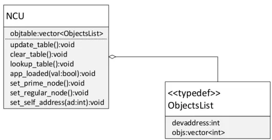
4.2.3 Network Control Unit . . . 51
4.2.4 Interface with Network Layer . . . 55
4.2.5 Interface with IP Core . . . 56
4.3 Network Layer . . . 56
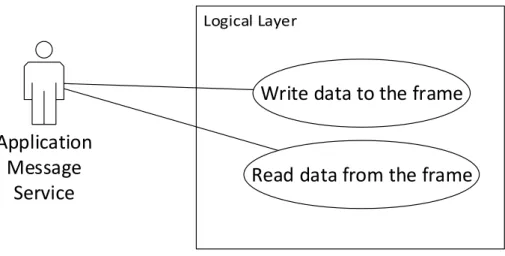
4.3.1 Application Message Exchange Service . . . 57
4.3.2 Media Streaming Control Service . . . 66
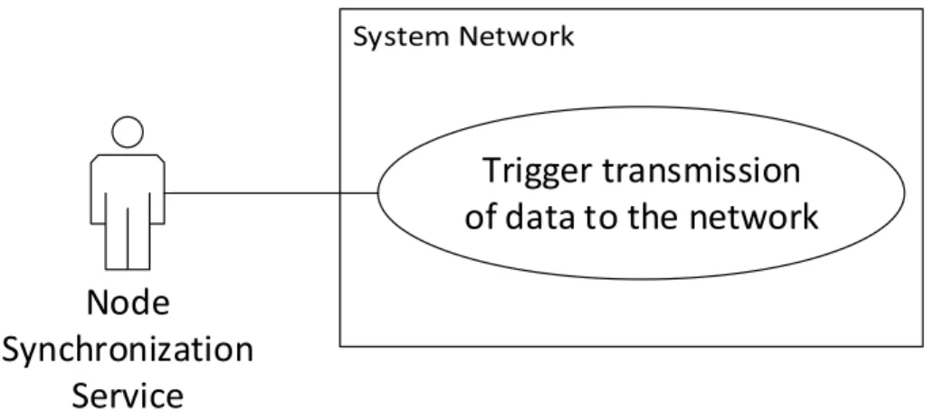
4.3.3 Node Synchronization Service . . . 68
4.3.4 Interface with IP Core . . . 70
4.4 Logical Layer . . . 71
4.4.1 Signal Modulation and Node synchronism . . . 76
4.4.2 Error handling . . . 79
4.4.3 Datagram structure . . . 80
4.5.1 Interface with external IP Cores . . . 82 5 Case Study 83 5.1 Results . . . 88 6 Conclusion 103 6.1 Future Work . . . 106 Bibliography 107
A Building Hybrid CPU+FPGA System via Xilinx EDK 125
B Integration of Custom IP in the Hybrid CPU+FPGA System 131
B.1 Creating peripheral template for custom IP integration . . . 131 B.2 Tailoring peripheral template to accommodate custom IP . . . 135
C Implementation of FSM for controlling datagram reception,
List of Figures
2.1 Propagation of light in the optical fiber core . . . 10
2.2 Coaxial cable cutaway . . . 11
2.3 Unshielded Twisted Pair cable cutaway . . . 12
2.4 Node interconnection in a Bus topology . . . 14
2.5 Node interconnection in a Star topology . . . 16
2.6 Node interconnection in a Ring topology . . . 17
2.7 Node interconnection in a Mesh topology . . . 18
4.1 Example of network oriented for media applications . . . 37
4.2 Network communication protocol - API for the developer . . . 39
4.3 Overview of a real case scenario . . . 40
4.4 UML Class diagram concerning API for the developer . . . 40
4.5 Workflow for assigning addresses to devices on the network . . . 42
4.6 Querying implemented object in each Network Node . . . 43
4.7 Establishing and terminating streaming connections . . . 44
4.8 Example of interface between Object and corresponding peripheral . 46 4.9 Transport Layer entities . . . 47
4.10 UML Class Diagram for Transport Layer . . . 48
4.11 Streaming Session Management Unit Software Architecture . . . 49
4.12 Node Control Unit controlling the node’s mode of operation . . . . 50
4.13 UML class diagram of the Node Control Unit Object . . . 51
4.14 Controlling the state of the bypass mechanism . . . 51
4.15 Network Control Unit effects on the Network Nodes and the Sys-tem’s Network . . . 52
4.16 Network Control Unit Software Architecture . . . 53
4.17 Network Layer entities . . . 57
4.18 UML Class Diagram for Network Layer . . . 58
4.20 Effects of the Application Message Exchange Service in the Logical
Layer . . . 60
4.21 Application Message Exchange Service Software Architecture . . . . 61
4.22 Writing operation in datagram, via PLB registers . . . 62
4.23 Reading inbound data, via PLB . . . 63
4.24 Executing commands based on received control data . . . 64
4.25 Media Streaming Control Service interaction with Logical Layer . . 67
4.26 Dynamic selection of channels for read/write operations . . . 68
4.27 Node Synchronization Service for ensuring periodic data transfer in the network . . . 69
4.28 Network communication protocol - Logical Layer . . . 70
4.29 Network communication protocol - Logical Layer . . . 71
4.30 Logical Layer interaction with Application Message Exchange Service 72 4.31 General overview of dataflow inside the network node . . . 72
4.32 Data treatment by the Network Node, in detail . . . 73
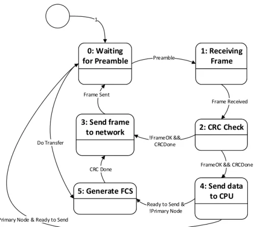
4.33 Finite State Machine for controlling data exchange and processing . 74 4.34 First bit of the frame start delimiter received . . . 77
4.35 Second bit of the frame start delimiter received . . . 78
4.36 Third bit of the frame start delimiter received . . . 78
4.37 Fourth bit of the frame start delimiter received . . . 79
4.38 Control data elements organization in the datagram infrastructure . 81 4.39 Time-sensitive data transport structure . . . 82
4.40 IP-to-IP Core interface, for time-sensitive data transport . . . 82
5.1 Implemented Network Node Internals . . . 84
5.2 Experimental Node interconnection in a Ring topology . . . 85
5.3 System Software Stack . . . 87
5.4 Node Synchronization Service triggering the transmission of the datagram . . . 94
5.5 Frame reception, integrity check and parsing by the Prime Node . . 94
5.6 Propagation of the datagram through the network . . . 97
5.7 Frame reception, integrity check and parsing by the Prime Node . . 97
5.8 Frame reception, integrity check and parsing by the Network Node 3 97 5.9 Frame reception, integrity check and parsing by the Prime Node . . 98
5.10 Inside the interrupt handler for parsing inbound messages . . . 100
5.11 Interrupt handler execution after a message has been sent out to the network . . . 101
A.1 Building Hybrid CPU+FPGA System via Xilinx EDK with the help of the setup wizard . . . 125 A.2 Building Hybrid CPU+FPGA System via Xilinx EDK -
Intercon-nect Bus solution selection and board specification importation . . . 126 A.3 Building Hybrid CPU+FPGA System via Xilinx EDK - Creation
of a new design from scratch . . . 126 A.4 Building Hybrid CPU+FPGA System via Xilinx EDK - Board
se-lection . . . 127 A.5 Building Hybrid CPU+FPGA System via Xilinx EDK based on
single or multiple processors . . . 127 A.6 Building Hybrid CPU+FPGA System via Xilinx EDK - Processor
configuration . . . 128 A.7 Building Hybrid CPU+FPGA System via Xilinx EDK - Selecting
peripherals for the application . . . 129 A.8 Building Hybrid CPU+FPGA System via Xilinx EDK - Processor
cache features . . . 129 B.1 Creating peripheral template for custom IP integration - Initial menu131 B.2 Creating peripheral template for custom IP integration . . . 132 B.3 Creating peripheral template for custom IP integration locally . . . 132 B.4 Creating peripheral template for custom IP integration - Assigning
a name to the peripheral . . . 133 B.5 Creating peripheral template for custom IP integration -
Intercon-nect Bus selection . . . 133 B.6 Creating peripheral template for custom IP integration - allocating
registers for communication between CPU and custom IP core . . . 134 B.7 Creating peripheral template for custom IP integration - PLB ports 134 B.8 Creating peripheral template for custom IP integration - automatic
generation of templates for software drivers and HDL source code . 135 B.9 Creating peripheral template for custom IP integration - mapping
newly created peripheral . . . 135 B.10 File to which custom IP’s source code is inserted . . . 136 B.11 Custom IP’s I/O ports to communicate with the rest of the system
design . . . 136 B.12 Instantiation of the custom IP’s module . . . 137 B.13 Peripheral’s top level design file . . . 138
B.14 Allowing custom IP’s I/O ports to interact with the exterior of the
PLB infrastructure . . . 138
B.15 Allowing custom IP’s I/O ports to interact with the exterior of the PLB infrastructure . . . 139
B.16 Allowing custom IP’s I/O ports to interact with the exterior of the PLB infrastructure . . . 140
B.17 Updating peripheral specification . . . 141
B.18 Updating peripheral specification in a previously created local pe-ripheral . . . 141
B.19 Inserting the same name of the existing peripheral to be updated . 142 B.20 Confirmation to overwrite the performed changes . . . 142
B.21 Importing HDL source files . . . 143
B.22 Selecting Peripheral Order Analysis file . . . 144
B.23 Setting peripheral as PLB slave . . . 144
List of Tables
2.1 In-vehicle network comparison . . . 9
2.2 Criteria for comparison between transmission paths . . . 13
2.3 Decision table - transmission paths matchup . . . 13
2.4 Criteria for interconnection topology comparison . . . 20
2.5 Decision table for node interconnection topology . . . 21
4.1 List of attributes for Audio Amplifier Object . . . 41
4.2 List of attributes for Disk Player Object . . . 42
4.3 Set of functions for interface with Transport Layer for node man-agement . . . 43
4.4 Set of functions for interface with Transport Layer for network man-agement . . . 43
4.5 Set of functions for interface with Transport Layer for synchronous connections management . . . 45
4.6 Framework available for Transport Layer entities . . . 55
4.7 Interface between Transport and Network Layers, for channel allo-cation, state and read/write operations . . . 56
4.8 Registers for interaction with the IP Core . . . 56
4.9 My caption . . . 70
4.10 Registers for controlling the datapath for time-sensitive data . . . . 71
4.11 Finite State Machine states description . . . 75
4.12 List of Finite State Machine conditions for triggering state change . 76 5.1 Register values for the test runs . . . 85
5.2 Structure of the datagram . . . 86 5.3 Structure and content of the System Management Frame Segment . 86
Abstract
The natural evolution of embedded systems resulted in a faster execution of tasks, increased possibility for including additional features, allied to lower power con-sumption and benefiting from ever-growing rates of integration as far as silicon is concerned. The automotive industry is not an exception with regards to the inte-gration of technology for a vast arrays of applications in systems which vary from entertainment of infotainment to systems related to vehicle safety and stability such as driver assists. The existence of diverse independent systems in modern cars, combined with the necessity of centralizing the user interface, simplifying the operation of the system and minimizing the user’s intervention, help to promote the comfort and reduce the likelihood of distractions taking place while driving. Modern communication oriented network standards, e.g. MOST or FlexRay, en-able information compatibility when exchanged between systems communicating over different protocols. Moreover, the coexistence of packet, control and time-sensitive information are ensured within timing requirements, providing a reliable QoS (Quality of Service) and by making use of a single physical transmission mean. Synchronized multimedia data (e.g. synchronized video and audio transmission) are example of this kind of (time-sensitive) information.
This dissertation proposes a framework for design and development of network distributed applications in the field of automotive infotainment, compliant with the industry standards and using FPGA technology in order to ensure the system requirements satisfaction and promote IP Core re-utilization.
Resumo
A evolução natural dos sistemas embebidos traduziu-se numa maior rapidez na ex-ecução de tarefas, a possibilidade de incluir mais funcionalidades, aliado a menores consumos energéticos e beneficiando de crescentes e elevadas taxas de integração ao nível de silício. A indústria automóvel não é excepção no que diz respeito à integração de tecnologia para as mais variadas aplicações, com ou sem tolerân-cia à falha, em sistemas que vão desde entretenimento ou infotainment a sis-temas relacionados com a estabilidade e segurança do veículo, como é exemplo as driver assists. Existem de vários sistemas independentes nos modernos veículos automóveis. Estes, combinados com a necessidade de centralização ao nível de interface com o utilizador, tornam imperativa a simplicidade da operação. Para tal, requerem a minimizaccão da intervenção do utilizador, promovendo o conforto e diminuindo a probabilidade de desconcentração durante o exercício de condução. Os mais modernos standards de redes de comunicação como é exemplo o MOST ou o FlexRay, permitem a compatibilidade de informação trocada entre sistemas que comunicam através de distintos protocolos de comunicação. Para além disso, ainda garantem a coexistência de informação de controlo, informação do entreten-imento e informação do tipo time-sensitive, onde os requisitos de temporização devem ser assegurados, mantendo uma qualidade de serviço fiàvel e fazendo uso de um único meio físico de transmissão. São exemplos deste tipo de informação, dados síncronos do tipo multimédia (e.g. streaming de àudio e vídeo de forma sincronizada). Pretende-se desenvolver uma framework para desenvolvimento de aplicações de rede distribuídas, do tipo infotainment e que beneficia a aplicação de tecnologias como FPGA, no offloading de computação para este dispositivo, como meio de garantir a satisfação dos requisitos, e promover a reutilização deste tipo de sistemas, mantendo o elevado desempenho na troca de dados e promovendo a portabilidade e a modularidade.
Chapter 1
Introduction
The growing number of entertainment components supplying and consuming all kinds of information in the automotive field increased the complexity of intercon-necting and the control of such components. The final user (driver or passengers) had and still has the need to operate all the components through different, individ-ual human machine interfaces. To build a system, each component must have the capability and ability to communicate with other components in such a way that the information can be used in real time. The infotainment Head Unit, sometimes also named system controller should govern all events in all components in such a way that the user is no longer confronted by the complexity of the system, but that requires considerable effort from the development point of view. Unless an integrative API is offered, enabling the design of an appropriate software structure around the logical representation of all components in the system controller. Still, several challenges in infotainment system design are faced, in order to comply with the flexibility and the scalability of the different market requirements over different levels of functionality and/or performance, provided by a unique but still efficient system architecture.
The FPGA technology closes such gap, as it allows for interfacing hardware in a more flexible and optimized way. The advantage of such a concept is a scalable approach providing a number of hardware devices, which can be re-configured by the FPGA code through the system software, as well as the fact that it promotes multiple IP Core integration, resulting in modularity and results in a briefer process of prototyping the system Besides promoting portability (due to its technological agnosticism), the true parallelism that is inherent to FPGA technology makes it possible to ensure timing and bandwidth requirements, as well as systemic-level
synchronism.
In order to ally the benefits of using FPGA technology and optimized development effort, employment of CPU+FPGA platform makes it possible to combine the easier development of applications in software and ensuring the timing bandwidth requirements of the system, by means of computational offload to FPGA fabric, being the most time consuming tasks then implemented in RTL. In order to further improve the development effort, embedded operating systems offer several services and an abstraction layer for the development of applications.
With this in mind, the idea is to develop a communication protocol and the cor-responding framework to support the design of media oriented distributed appli-cations, following the OSI Reference Model, using FPGA technology as a mean of ensuring the coexistence of both control and time-sensitive data as well as meeting the performance demands and functional requirements of media oriented applications, combined with a CPU where software implemented parts of the com-munication protocol and framework are deployed, in order to ease the design of the whole system.
1.1
Document organization
The remainder of this document contains, firstly, the State of the Art, where the essential concepts and definitions to understand the actual work, are explained. Afterwards, comes the description of the Hardware Platforms used in this project and the related choices regarding this topic. The stack of the network protocol is examined and the design of the different parts of the communication protocol are presented. Following that, the Study Case evaluates the implemented parts of the project under test and documents the associated results. Moreover, the Conclusion chapter comprises with considerations about the obtained results and the lessons learned throughout the process of developing this dissertation. Finally, improvements that can be done to the showcased system are proposed.
Chapter 2
State of the Art
In the past, automotive manufacturers connected electronic devices in vehicles using point-to-point wiring systems.
Manufacturers began using more and more electronics in vehicles, which resulted in bulky wire harnesses that were heavy and expensive.
They then replaced dedicated wiring with in-vehicle networks, which reduced wiring cost, complexity, and weight. Several in-vehicle networks standards have been emerging, such as CAN (Controller Area Network), FlexRay and MOST (Media Oriented Systems Transport).
2.1
Controller Area Network
The CAN protocol was quickly adopted by the automotive industry, as a result of its simplicity, given that every Electronic Control Unit only requires a single CAN port to be connected to the network, instead of as many digital ports (and point-to-point connections) as the number of devices to be interconnected. There-fore, cost and weight are kept to a minimum. Moreover, every appended devices to the network are able to check the messages, as they are broadcasted within the whole network. Thus, the addition of new nodes to the CAN network has no im-pact on the way the network works and the existing nodes exchange information. The support for defining priorities to more important messages allows uninter-rupted transmission of higher priority messages, contributing to a greater level of determinism offered by this network. Besides, not only does this protocol perform
message integrity check, but also orders transmission nodes that are transmitting too many corrupted messages to suspend its communications and disconnect from the network, so that the correct functioning of the network is assured, in case a node is malfunctioning.
2.2
FlexRay
For automotive industry to continuously improve safety and performance, reduce environmental impact and enhance comfort, the speed, reliability and size of data bandwidth within car’s electronic control units (ECU) is scaling proportionally. Modern control strategy and safety systems, combining multiple sensors, actu-ators and ECUs, begin to require synchronization and performance beyond the existing standards can provide. Coupled with growing bandwidth requirements with today’s advanced vehicles there is a demand for a next-generation embed-ded network. The FlexRay protocol is a time-triggered protocol that provides options for deterministic data that arrives in a predictable time frame (down to the microsecond) as well as a dynamic event-driven data to handle a large variety of frames. FlexRay accomplishes this hybrid of core static frames and dynamic frames with a pre-set communication cycle that provides a pre-defined communi-cation cycle space for static and dynamic data. In order to guarantee a greater bandwidth and prevent data collision and consequently data frame corruption, FlexRay manages multiple nodes with a TDMA (Time Division Multiple Access) scheme. Every FlexRay node is synchronized to the same clock, and each node waits for its turn to write on the bus. Because the timing is consistent with a TDMA scheme, FlexRay is able to guarantee the consistency of data delivery to nodes on the network, which provides many advantages for systems that depend on up-to-date data between nodes.
2.3
MOST - Media Oriented Systems Transport
The infotainment sector in cars has developed rapidly within the last few years. Where an AM/FM tuner was initially sufficient, many vehicles are now equipped with high-grade sound and navigation systems. This also increases the number of devices involved - radio, cell phone, CD changer, navigation system, voice opera-tion and an addiopera-tional multi-channel amplifier supplement the primary systems.
These devices must interact in concert with each other and can only be controlled via a central operating surface to ensure drivers are not unnecessarily distracted. The bandwidth of the CAN-Bus, which can only move control signals, but no audio and video signals, is no longer sufficient for these demands. MOST, Me-dia Oriented Systems Transport, a communication system with a new, flexible architecture, used by many different manufacturers, was developed to meet these demands. It can transmit audio signals synchronously, as in telephones, and is the most widely used multimedia system in cars today. The MOST system not only comprises all layers of the Open System Interconnect (OSI) Reference Model for communication and computer network design, but also standardizes the inter-faces with the applications (e.g., an AM/FM tuner), which are defined as function blocks, enabling the developer to design multi-media systems on a relatively high abstraction level.
2.3.1
CAN vs FlexRay vs MOST for multimedia oriented
applications
Even though protocols such as CAN and FlexRay present high-reliability in terms of data transmission as well as determinism, other requirements must be met in order to support modern distributed infotainment applications. The Table 2.1 puts the CAN, FlexRay and MOST networks into comparison, in terms of peak bandwidth, coupled with a few examples about typical application in which each protocol is employed.
Table 2.1: In-vehicle network comparison
CAN FlexRay MOST150
Maximum
Bandwidth 1 Mbit/s 10 Mbit/s 150 Mbit/s
Typical Applications Powertrain (Engine, Transmission, ABS) High-Performance Powertrain, Safety (Drive-by-wire, active suspension, adaptive cruise control) Distributed infotainment systems
It can be concluded that the MOST standard is the most suitable protocol for multimedia transmission not only due to the higher peak bandwidth, but also
be-cause it grants coexistence between time-sensitive (e.g., synchronized video and audio streaming) and control-information, due to the data frame structure. Be-sides, networks with distinct protocols, such as CAN, FlexRay or Ethernet, can be integrated by means of gateways in a MOST network, consequently providing support for networks inter-communication.
2.4
Transmission Paths
In-vehicle network signals are subject to Radio Frequency and/or Electromagnetic interferences, which are known to compromise its integrity. This section will focus on solutions that overcome such issues, such as Optical Fiber, Coaxial and Twisted-Pair cable.
2.4.1
Optical Fiber
Optical fibers are utilized more and more frequently for applications with a high data rate due to increasing EMC requirements (Electromagnetic Compatibility). Transmission lines with optical fibers do not cause any interference radiation and are insensitive to electromagnetic interference irradiation (Electromagnetic Inter-ference, EMI). In contrast to shielded electric data lines, optical fibers are, more-over, lighter and more flexible and can thus be handled more easily. Furthermore, optical fiber provides far greater bandwidth than copper and has standardized performance up to 10Gbps, being the modulation frequency of the transceivers the only limiting factor. The extra cost of the optical transceivers and the higher costs of equipment for testing/diagnosing optical fiber based circuits is however a negative aspect, comparing to the electrical transmission paths.
Acceptance cone
Cladding
Cladding Core
2.4.2
Coaxial cable
Coaxial cable conducts electrical signal using an inner conductor (usually a solid copper, stranded copper or copper plated steel wire) surrounded by an insulating layer and all enclosed by a shield, typically one to four layers of woven metallic braid and metallic tape. The cable is protected by an outer insulating jacket. Normally, the shield is kept at ground potential and a voltage is applied to the center conductor to carry electrical signals. The advantage of coaxial design is that electric and magnetic fields are confined to the dielectric with little leakage outside the shield. Conversely, electric and magnetic fields outside the cable are largely kept from causing interference to signals inside the cable. Larger diameter cables and cables with multiple shields have less leakage. This property makes coaxial cable a good choice for carrying weak signals that cannot tolerate interference from the environment or for higher electrical signals that must not be allowed to radiate or couple into adjacent structures or circuits. Coaxial cable is used as a transmission line for radio frequency signals. Its applications include feedlines connecting radio transmitters and receivers with their antennas, computer network (Internet) connections, and distributing cable television signals.
plastic jacket
dielectric insulator
metallic shield
centre core
Figure 2.2: Coaxial cable cutaway
2.4.3
Twisted-Pair cable
Low-voltage differential signaling, or LVDS, also known as TIA/EIA-644, is a technical standard that specifies electrical characteristics of a differential, serial communications protocol. LVDS operates at low power and can run at very high
speeds using inexpensive twisted-pair copper cables. LVDS was introduced in 1994, and has become popular in products such as LCD-TVs, automotive info-tainment systems, industrial cameras and machine vision, notebook and tablet computers, and communications systems. The typical applications are high-speed video, graphics, video camera data transfers, and general purpose computer buses. LVDS is a differential signaling system, meaning that it transmits information as the difference between the voltages on a pair of wires; the two wire voltages are compared at the receiver. As long as there is tight electric- and magnetic-field coupling between the two wires, LVDS reduces the generation of electromagnetic noise. This noise reduction is due to the equal and opposite current flow in the two wires creating equal and opposite electromagnetic fields that tend to cancel each other. In addition, the tightly coupled transmission wires will reduce susceptibil-ity to electromagnetic noise interference because the noise will equally affect each wire and appear as a common-mode noise. The LVDS receiver is unaffected by common mode noise because it senses the differential voltage, which is not affected by common mode voltage changes.
conductor insulation pair
sheath
UTP
Figure 2.3: Unshielded Twisted Pair cable cutaway
2.4.4
Conclusions
Taking into account the increasing Electromagnetic Interference which in-vehicular networks are subject to and the increasing bandwidth requirements due to the growing integration of devices, specially as far as multimedia systems are con-cerned, optical fiber is the most suitable solution from a performance vs cost
Table 2.2: Criteria for comparison between transmission paths
Criteria Description
Cost Cost of the transmission path and corresponding transceivers Reliability Durability and reliable data transmission
under environments with high EMI and RFI
Weight Weight of the wiring loom
Ease of assembly/handling Robustness of the cabling and capability to be mounted in tight spaces
Table 2.3: Decision table - transmission paths matchup
Criteria Optical Fiber Coaxial Cable UTP Cable
Cost 4 4 5
Reliability 5 4 3
Weight 5 3 4
Ease of assembly/handling 4 4 5
Total Score 18 15 17
standpoint, not to mention the material’s lighter weight, as described in the deci-sion table, 2.2 and 2.3
However, with regards with this dissertation, as the project is developed in a laboratory where interferences are less likely to occur and due to time and cost constraints, the employment of the LVDS technique with Unshielded Twisted Pair Cables provides a reliable data transfer under these circumstances.
2.5
Node positioning and interconnection
The Physical Layer defines the structure of interconnected devices, that is, the positioning of the nodes in the network, the cabling layout and the employed type of cabling. This chapter is dedicated to the exploration of an array of network physical topologies, followed by the selection of the most suitable topology for the system that is to be developed, according to the trade-offs each method offers. Moreover, considerations will be drawn about transmission paths which ensure fast and reliable data exchange under environments where Radio-Frequency and Electromagnetic interferences are prone to occur, as is the case with vehicles. Af-terwards, comes the choice of the most convenient solution that meets the system’s requirements and constraints. In this section, the main aspects of well-known
net-work topologies are meant to be analysed, having special attention to how far scalability goes while still ensuring the timing and bandwidth requirements as well as implications of the resulting wiring loom and if it is appropriate to reliably transport time-sensitive data. The topologies to be studied are:
• Bus Network • Star Network • Ring Network • Mesh Network
2.5.1
Bus Network
In a Bus Network, the devices are attached to a shared communication line, also known as backbone, which has signal terminators at its ends in order to prevent the data to be reflected back, thus causing collisions.
A host exists for network management purposes, which similarly to all the inter-connected nodes, receives all the network traffic and has the same transmission priority.
The definition of a node as a Bus Master or the employment of a Media Access Control technology, such as Carrier Sense Multiple Access (CSMA) handle data collisions, in case multiple nodes simultaneously transmit data.
Unless the shared communication line fails, the normal operation of the devices is not compromised upon failure of a node in the network.
The figure 2.4 illustrates the connection of the nodes to the backbone.
Shared communica�on line
Figure 2.4: Node interconnection in a Bus topology
• The process of installation of a new node in the network is simple
• Requires less cable length than a Star Network Topology, thus resulting in lower costs and less weight of the wiring loom
There are also some limitations to take into consideration:
• A break in the main cable, which is a difficult problem to identify, may lead to a failure in the operation of the whole system
• The available bandwidth is reduced as more devices are attached to the network, which is not ideal for large networks
• Data collisions may be more frequent as more nodes are interconnected by means of this topology, consequently resulting in determinism not to be verified and possible failure to meet the timing requirements, which is not acceptable as the system involves the transport of time-sensitive data
2.5.2
Star Network
A Star Network is composed by a central node to which all other nodes are con-nected. The Central Node is responsible for rebroadcasting an incoming message to all the nodes in the network. If the Central Node is passive, it rebroadcasts the message to all the existing nodes in the network, including the echo to the node the incoming message came from. Therefore the node from which the message originated from, must have mechanisms that identify and handle the echoes. If however, the Central Node is active, it can prevent echo messages to be sent to the corresponding peripheral node.
The figure 2.5 illustrates the interconnection of the nodes by means of the Central Node.
The following advantages from this topology are outlined in the following topics: • The normal operation of the nodes may not be affected if one leaf node fails
or unless the central node functions abnormally
• The bandwidth and the delay in the transmission to any leaf node is un-changed as more nodes are attached to the network, as long as the capacity of the Central Node is not exceeded
Central Node
Figure 2.5: Node interconnection in a Star topology
• Centralization is beneficial as it enables easier traffic analysis and the detec-tion of eventual malfuncdetec-tions
However, there are drawbacks that should be taken into consideration:
• The number of nodes attached to the network is limited by the capacity of the central node, which disfavours scalability, not to mention the increasing costs as more capable central nodes are required
• More cable length is required, compared to Bus or Ring networks, thus re-sulting in greater expenses in terms of costs and weight (of the wiring loom) • The communication relies on the central node, which is a single point of
failure that can compromise the whole system
2.5.3
Ring Network
With regards to the Ring Network topology, each node is connected to two other nodes by means of a single pathway, resulting in a circular network structure through which data travels unidirectionally. All nodes have the same transmission priority, provided that the data has to pass through each one, as it travels around the ring. The figure 2.6 illustrates the connection of the nodes in a ring topology.
Figure 2.6: Node interconnection in a Ring topology
Advantages are explained in the following topics:
• The process of installation of a new node and reconfiguration of a new node is easy, given that it only requires moving one connection between two nodes. • Under heavy network load, the performance degradation is fewer than on
the Bus Network topology.
• Every node has access to the token and opportunity to transmit, coupled with the impossibility for data collisions to occur
• The system’s integrity does not depend on solely one node (as is the case with the Star Network topology, which requires a central node)
• Faults in the system, that is, ring breaks, are easy to spot provided that a single pathway interconnects two nodes
• Adding an extra node requires only one extra cable, resulting in little extra weight added
As disadvantages:
• The procedures to start-up and shut down are more complex than with the Start network topology
• The communication delay increases with the number of nodes appended to the network
• One malfunctioning node may interrupt the communications, unless a bypass is integrated in each device, enabling data to proceed to the next nodes
2.5.4
Mesh Network
In this type of topology, a point-to-point connection exists between each pair of nodes in the system, except if it is about a Partial Mesh. If a failure occurs in any of the transmission paths, self healing mechanisms reconfigure the network, establishing alternative paths to ensure data reaches the destination. The figure 2.7 illustrates the connection of the nodes in a mesh topology. A strong point of this
Figure 2.7: Node interconnection in a Mesh topology
network topology is the reliability, because redundant paths may exist. However, the amount of cabling required, and consequently the cost and weight are way higher compared to the aforementioned network topologies.
2.5.5
Conclusions
It is now known any of the aforementioned network topologies have at least one weak spot that can render a system unable to be fail safe. Even though the Mesh Network topology, with its self healing mechanisms, presents less risks of leading a system to operate abnormally, not only the choice of this topology would have an huge impact in terms of costs, but also on weight, as a result of the amount of cabling required increases exponentially as more devices are integrated in the network.
The Bus Network would be a great alternative, as it covers some of the disadvan-tages of the Mesh Network topology, however, as more devices are attached to the network, the bandwidth is affected negatively, thus limiting the dimension of a sys-tem as far as scalability is concerned. We are left with two contenders: Ring and Star topologies. Although the Star network topology provides less node-to-node delay than the Ring Network, the use of a Central Node is a limiting characteristic from a system scalability standpoint.
However, the delay each node provokes in the Ring Network topology may be drastically reduced by means of CPU offloading/Hardware Acceleration of parts of the system’s application using FPGA technology, consequently allowing the timing requirements to be ensured. Besides, although the Ring network topology requires a more complex process in order to initialize the system, this is not a critical aspect, as it does not affect the post system setup phase. On top of that, the amount of cabling required is fewer, which comes as a point in favor of the Ring topology, provided that weight saving is an important aspect in the automotive industry, not to mention budget control.
To conclude, the Ring Network topology offers the best trade-off and shall be the chosen one.
The table 2.4 contains the criteria that were taken into consideration for choosing the most adequate topology for the system to be worked on.
Table 2.4: Criteria for interconnection topology comparison
Criteria Description
Performance Degradation
Reduction of available bandwidth as more nodes are attached to the network
Wiring Loom Required wiring loom to
interconnect nodes
Node Complexity
Development effort to integrate the features to interact with the network
Reliability
How the system’s integrity is compromised, in an event of a failure in a node or transmission path
Table 2.5: Decision table for node interconnection topology Criteria Star Topology Bus Topology Ring Topology Mesh Topology Performance Degradation 5 4 5 3 Wiring Loom 3 5 4 2 Node Complexity 3 4 5 3 Reliability 5 3 4 5 Score 16 16 18 13
Afterwards, the table 2.5 consists of a decision matrix, where a score is assigned to each topology, with regards to each criteria, according to what was studied in the previous subsections. The score varies between 0 and 5, meaning the punctuation of 5, the fact that the topology performs better than all other in a given aspect. If more than one topologies perform similarly, both get the same points, otherwise a score the immediately inferior value is assigned.
2.6
Electronic Design Automation tools
Digital circuit design has evolved rapidly over the last 25 years. The earliest digital circuits were designed with vacuum tubes and transistors. Integrated circuits were then invented where logic gates were placed on a single chip. The first integrated circuit (IC) chips were SSI (Small Scale Integration) chips where the gate count was very small. As technologies became sophisticated, designers were able to place circuits with hundreds of gates on a chip. These chips were called MSI (Medium Scale Integration) chips. With the advent of LSI (Large Scale Integration), designers could put thousands of gates on a single chip. At this point, design processes started getting very complicated, and designers felt the need to automate these processes. Electronic Design Automation (EDA) techniques began to evolve. Chip designers began to use circuit and logic simulation techniques to verify the functionality of building blocks of the order of about 100 transistors. The circuits were still tested on the breadboard, and the layout was done on paper or by hand on a graphic computer terminal.
With the appearance of VLSI (Very Large Scale Integration) technology, designers could design single chips with more than 100,000 transistors. As a result of the complexity of these circuits, it was not possible to verify these circuits on a
bread-board. Computer- aided techniques became critical for verification and design of VLSI digital circuits. Computer programs to do automatic placement and routing of circuit layouts also became popular. The designers were now building gate-level digital circuits manually on graphic terminals. They would build small building blocks and then derive higher-level blocks from them. This process would continue until they had built the top-level block. Logic simulators came into existence to verify the functionality of these circuits before they were fabricated on chip. As designs got larger and more complex, logic simulation assumed an important role in the design process. Designers could iron out functional bugs in the archi-tecture before the chip was designed further.
2.7
Hardware Description Languages
For a long time, programming languages such as FORTRAN, Pascal, and C were being used to describe computer programs that were sequential in nature. Sim-ilarly, in the digital design field, designers felt the need for a standard language to describe digital circuits. Thus, Hardware Description Languages (HDLs) came into existence, allowing the designers to model the concurrency of processes found in hardware elements. Hardware description languages such as Verilog HDL and VHDL became widely used, being Verilog HDL originated in 1983 at Gateway Design Automation and VHDL developed under contract from DARPA.
Even though HDLs were popular for logic verification, designers had to manually translate the HDL-based design into a schematic circuit with interconnections between gates. The release of logic synthesis tools in the late 1980s changed the design methodology radically. Digital circuits could be described at a register transfer level (RTL) by use of an HDL. Thus, the designer had to specify how the data flows between registers and how the design processes the data. The details of gates and their interconnections to implement the circuit were automatically extracted by logic synthesis tools from the RTL description.
Thus, logic synthesis pushed the HDLs into the forefront of digital design. De-signers no longer had to manually place gates to build digital circuits. They could describe complex circuits at an abstract level in terms of functionality and data flow by designing those circuits in HDLs. Logic synthesis tools would implement the specified functionality in terms of gates and gate interconnections.
HDLs also began to be used for system-level design. HDLs were used for simulation of system boards, interconnect buses, FPGAs (Field Programmable Gate Arrays), and PALs (Programmable Array Logic). A common approach is to design each IC chip, using an HDL, and then verify system functionality via simulation.
Today, Verilog HDL is an accepted IEEE standard. In 1995, the original standard IEEE 1364-1995 was approved. IEEE 1364-2001 is the latest Verilog HDL standard that made significant improvements to the original standard.
HDLs have many advantages compared to traditional schematic-based design. • Designs can be described at a very abstract level by use of HDLs. Designers
can write their RTL description without choosing a specific fabrication tech-nology. Logic synthesis tools can automatically convert the design to any fabrication technology. If a new technology emerges, designers do not need to redesign their circuit. They simply input the RTL description to the logic synthesis tool and create a new gate-level netlist, using the new fabrication technology. The logic synthesis tool will optimize the circuit in area and timing for the new technology.
• By describing designs in HDLs, functional verification of the design can be done early in the design cycle. Since designers work at the RTL level, they can optimize and modify the RTL description until it meets the desired functionality. Most design bugs are eliminated at this point. This cuts down design cycle time significantly because the probability of hitting a functional bug at a later time in the gate-level netlist or physical layout is minimized. • Designing with HDLs is analogous to computer programming. This also
pro-vides a concise representation of the design, compared to gate-level schemat-ics. Gate-level schematics are almost incomprehensible for very complex designs.
With rapidly increasing complexities of digital circuits and increasingly sophisti-cated EDA tools, HDLs are now the dominant method for large digital designs. The speed and complexity of digital circuits have increased rapidly. Designers have responded by designing at higher levels of abstraction. Designers have to think only in terms of functionality. EDA tools take care of the implementation details. With designer assistance, EDA tools have become sophisticated enough to achieve a close-to-optimum implementation.
Behavioral synthesis allowed engineers to design directly in terms of algorithms and the behavior of the circuit, and then use EDA tools to do the translation and optimization in each phase of the design. However, behavioral synthesis did not gain widespread acceptance. Today, RTL design continues to be very popular. Verilog HDL is also being constantly enhanced to meet the needs of new verification methodologies.
New verification languages have also gained rapid acceptance. These languages combine the parallelism and hardware constructs from HDLs with the object ori-ented nature of C++. These languages also provide support for automatic stimulus creation, checking, and coverage. However, these languages do not replace Verilog HDL. They simply boost the productivity of the verification process. Verilog HDL is still needed to describe the design.
For very high-speed and timing-critical circuits like microprocessors, the gate-level netlist provided by logic synthesis tools is not optimal. In such cases, designers often mix gate-level description directly into the RTL description to achieve opti-mum results. This practice is opposite to the high-level design paradigm, yet it is frequently used for high- speed designs because designers need to meet strict tim-ing requirements out of circuits, and EDA tools sometimes prove to be insufficient to achieve the desired results, even though these are always evolving.
2.8
Standard integration and reuse of processor,
system and peripheral cores
System-on-a-chip (SoC) and ASIC silicon densities now support system-level im-plementations. The buses to link processors, memory, peripherals, and special functions are necessary. On-chip multilevel bus systems have emerged to meet these needs. One is the CoreConnect on-chip bus system from IBM Microelec-tronics. Originally designed to support PowerPC cores for IBM ASICs, this bus system now handles other processors and can be licensed for deployment.
CoreConnect is an on-chip silicon bus bundle for ASIC or FPGA designs. It con-sists of a three-level system: the processor local bus (PLB), the on-chip peripheral bus (OPB), and the device control register (DCR) bus. The first bus, the PLB, connects the processor to high-performance peripherals, such as memory, DMA controllers, and fast devices. Bridged to the PLB, the OPB supports the
slower-speed peripherals. The third bus, the DCR, is a separate control bus that links to all of the devices, controllers, and bridges. It provides a separate path to set and monitor the individual control registers.
2.8.1
Processor Local Bus
The PLB is the main on-chip system bus. It links the processor with on-chip memory, memory controllers, and other high-speed peripherals, including DMA controllers. It’s a synchronous, multimaster, arbitrated bus. For higher through-put, it supports concurrent Reads and Writes, even for the same master. As a result, each master has a single 32-bit address bus plus separate Read and Write buses, which can be implemented as 32, 64, and 128 bits wide. The design even allows 256-bit-wide data buses.
Also, the PLB supports pipelined addressing, enabling masters to re-quest bus access while the current transaction(s) are executing. It implements four priority levels of bus access. Plus, masters can lock the bus for atomic operations, keeping out any other master until they have completed the locked transaction(s). Trans-action address cycles have three phases; request, transfer, and acknowledge. Data cycles have two phases; transfer and acknowledge. The acknowledge phase can oc-cur in the trailing portion of the same clock for the transfer phase of a single-clock data transfer.
The centerpiece of the PLB bus is the PLB macro, which includes the arbiter and bus multiplexer switch. Each bus master connects its arbitration signals, bus control signals, address bus, and Read and Write data buses to the arbiter, which functions like a giant multiplexer. Concurrently, the PLB can support a Read and a Write through its multiplexer. It only presents one master’s address bus at a time, though, starting one transaction at a time. The arbiter supports up to 16 masters, with no logical restrictions on the number of slave devices.
The PLB implements an interesting variation of a split-transaction and a forward split-transaction. The traditional split-transaction separates the master request from the slave response. This is invaluable for making Reads effective, giving the device time to get its data ready to transfer. In contrast, CoreConnect’s PLB permits masters to make early requests to the slave before the bus is allocated to them. This early warning enables the addressed device to set up before the bus is allocated to the master’s request.
The PLB supports both fixed- and variable-length bursts. The fixed-length bursts are defined by a 3-bit field in the transaction request. Variable-length transactions are controlled by the master bus control signals.
Address pipelining also enables the bus to start a new transaction before the current transaction completes. This means that a Read or a Write can be started during a Write or a Read transaction in a master. The new transaction might be for the existing master or another master.
For larger systems with multiple CoreConnect PLB buses, IBM has provided two crossbar switches. These switch cores let designers link multiple on-chip PLBs through a central clearinghouse switch.
2.8.2
On-Chip Peripheral Bus
Designed to support slower peripherals, the OPB is implemented as a straightfor-ward multimaster, arbitrated bus. It’s a synchronous bus with a common clock, but its devices can run with slower clocks, as long as all of the clocks’ rising edges are in sync with the rising edge of the main clock. This bus uses a distributed multiplexer implementation.
The OPB implements a 32-bit address bus and a separate 32-bit data bus. Trans-action widths can be full-word, half-word, or byte-size. The bus supports 8-, 16-, and 32-bit wide device interfaces (aligned on the left-most byte). Data transactions can take a single cycle (for matched clocks), and burst operations are supported. The bus masters compete for the bus via the arbiter. Each master connects directly to the arbiter via its Mn_request (bus request), Mn_busLock (bus lock), and OPB_MnGrant (bus grant) signals. A master may request to lock the bus, holding it until the bus is released.
OPB consists of two multiplexer-based buses: the OPB address bus (OPB_ABus) and the OPB data bus (OPB_Dbus). The address bus gates the selected master’s address bus to the devices, and through "AND" and "OR" gating, the data bus picks up the selected master’s data bus (Mn_Dbus) for a Write or the addressed slave’s data bus (SIO_DBus) for a Read.
Each clocked data transfer includes a transfer-acknowledge signal from the slave device indicating completion of the data transfer. If the slave device can’t complete
the data transfer or accept the transfer request, it can assert an error-acknowledge signal, Sin_errAck ("Ored" to create OPB_errAck, the OPB error acknowledge). The OPB supports built-in DMA peripheral controllers with a special DMA chan-nel. The DMA channel arbitrates for control of the PLB like a master.
2.8.3
Device Control Register Bus
The DCR bus provides an alternative path to the system for setting the individual device control registers. With it, the host CPU can set up the device-control-register sets without loading down the main PLB. This bus has a single master, the CPU interface, which can Read or Write to the individual device control reg-isters. The bus employs a ring implementation to connect the CPU interface to the devices, which are addressed via a 10-bit address bus. A separate 32-bit data bus transfers register data. (On-chip silicon is cheap.)
This is a synchronous bus. The individual devices can run at a slower clock rate than the bus clock, but the rising edge of the device clocks must correspond to that of the faster DCR bus clock. The CPU, the master, connects to each slave device with its address bus, data bus, and control signals (dcrWrite, dcrRead). The output bus of the slave devices connects to the CPU interface via a multiplexer "OR" function. The addressed device simultaneously signals receipt of a Read transaction and the end of a Write transaction. Bursts aren’t supported by this bus. Each transaction takes a minimum of three cycles (more with slower device clocks).
2.9
Interrupts
An interrupt is a signal to the processor emitted by hardware or software indicating an event that needs immediate attention. An interrupt alerts the processor to a high-priority condition requiring the interruption of the current code the processor is executing. The processor responds by suspending its current activities, saving its state, and executing a function called an interrupt handler (or an interrupt service routine, ISR) to deal with the event. This interruption is temporary, and, after the interrupt handler finishes, the processor resumes normal activities.[1] There are two types of interrupts: hardware interrupts and software interrupts.
Hardware interrupts are used by devices to communicate that they require atten-tion from the operating system.[2] Internally, hardware interrupts are implemented using electronic alerting signals that are sent to the processor from an external de-vice, which is either a part of the computer itself, such as a disk controller, or an external peripheral.
2.9.1
Edge-triggered interrupts
An edge-triggered interrupt is an interrupt signalled by a level transition on the interrupt line, either a falling edge (high to low) or a rising edge (low to high). A device, wishing to signal an interrupt, drives a pulse onto the line and then releases the line to its inactive state. If the pulse is too short to be detected by polled I/O then special hardware may be required to detect the edge.
2.10
Sequential flow in FPGA
Even though FPGAs are able to perform pure parallel tasks, contrary to multi-threading in single core CPUs, where part of each tasks is executed one at a time, assuming they are assigned the same priority. FPGAs are often called upon to perform sequence and control-based actions such as implementing a simple com-munication protocol. For a designer, the best way to address these actions and sequences is by using a state machine. State machines are logical constructs that transition among a finite number of states. A state machine will be in only one state at a particular point in time. It will, however, move between states depending upon a number of triggers.
Theoretically, state machines are divided into two basic classes (Moore and Mealy) that differ only in how they generate the state machine outputs. In a Moore type, the state machine outputs are a function of the present state only. A classic example is a counter. In a Mealy state machine, the outputs are a function of the present state and inputs.
2.11
Audio properties
Digital audio (including digitized speech and music) has significantly lower band-width requirements than video. Digital audio, however, has its own unique proper-ties that must be considered when designing multimedia network applications. To understand these properties, let’s first consider how analog audio (which humans and musical instruments generate) is converted to a digital signal:
• The analog audio signal is sampled at some fixed rate, for example, at 8,000 samples per second. The value of each sample is an arbitrary real number. • Each of the samples is then rounded to one of a finite number of values. This
operation is referred to as quantization. The number of such finite values - called quantization values - is typically a power of two, for example, 256 quantization values.
• Each of the quantization values is represented by a fixed number of bits. For example, if there are 256 quantization values, then each value - and hence each audio sample - is represented by one byte. The bit representations of all the samples are then concatenated together to form the digital representation of the signal. As an example, if an analog audio signal is sampled at 8,000 samples per second and each sample is quantized and represented by 8 bits, then the resulting digital signal will have a rate of 64,000 bits per second. For playback through audio speakers, the digital signal can then be converted back - that is, decoded - to an analog signal. However, the decoded analog signal is only an approximation of the original signal, and the sound quality may be noticeably degraded (for example, high-frequency sounds may be missing in the decoded signal). By increasing the sampling rate and the number of quantization values, the decoded signal can better approximate the original analog signal. Thus (as with video), there is a trade-off between the quality of the decoded signal and the bit-rate and storage requirements of the digital signal.
The basic encoding technique that we just described is called pulse code mod-ulation (PCM). Speech encoding often uses PCM, with a sampling rate of 8,000 samples per second and 8 bits per sample, resulting in a rate of 64 kbps. The audio compact disk (CD) also uses PCM, with a sampling rate of 44,100 samples per second with 16 bits per sample; this gives a rate of 705.6 kbps for mono and 1.411 Mbps for stereo. PCM-encoded speech and music, however, are rarely used in the
Internet. Instead, as with video, compression techniques are used to reduce the bit rates of the stream. Human speech can be compressed to less than 10 kbps and still be intelligible. A popular compression technique for near CD-quality stereo music is MPEG 1 layer 3, more commonly known as MP3. MP3 encoders can compress to many different rates; 128 kbps is the most common encoding rate and produces very little sound degradation. A related standard is Advanced Audio Coding (AAC), which has been popularized by Apple. As with video, multiple versions of a prerecorded audio stream can be created, each at a different bit rate. Although audio bit rates are generally much less than those of video, users are generally much more sensitive to audio glitches than video glitches. Consider, for example, a video conference taking place over the Internet. If, from time to time, the video signal is lost for a few seconds, the video conference can likely proceed without too much user frustration. If, however, the audio signal is frequently lost, the users may have to terminate the session.
A multimedia system in a vehicle must be able to read the different storage media and their coding formats. In addition, the different transmission formats of digital audio broadcasting and digital video broadcasting must be identified. Depending on the equipment variant, high transmission rates may be generated, which must be processed by the system. In contrast to the vast majority of other bus systems coming from different application areas, this system has been designed for Mul-timedia Data Transport throughout a system, as its name already indicates. In contrast to home systems, the car requires a multi source / multi sink environ-ment, where multiple audio and video sinks, amplifiers, headphones and multiple displays are operated at the same time. There is a great variety of transmission formats in the audio field. In addition to stereo reproduction, different surround formats are relevant for the use in vehicles and are often employed in professional systems. The following is a rough overview:
2.11.1
Stereo
The uncompressed signal has a data rate of 1.4 Mbit/s at a sampling rate of 44.1 kHz and a 16-bit resolution. The most widely used compression rate is 128 kBit/s for MP3.
2.11.2
Analog Dolby Surround Pro Logic
This system consists of the channels front right, front center (center speaker for voices), front left, and rear left, rear right as one channel. The surround channel is applied to the two rear speakers and is time-delayed with regard to the front channels and band-limited to 100 to 7,000 Hz. The center speaker positions the voices to the center, which, in a car, makes localization rather independent of the listening position.
2.11.3
Analog Dolby Surround Pro Logic II
The Dolby Surround Pro Logic II enhances the Pro Logic to a 5.1 system by incor-porating two separate surround channels without band limitation, and a subwoofer channel. 18.5 Audio and Video Transmission Formats 299
2.11.4
Dolby Digital, AC3
AC3 comprises five separate channels without band limitation and a separate sub-woofer channel (Low Frequency Effect, LFE) limited to 120 Hz. At a sampling frequency of 48 kHz and a 16-bit resolution, transmission rates of 384 to 448 kbit/s accrue for the data which have a lossy compression ratio of 10:1. For two-channel stereo, the data rate is reduced to 192 kBit/s. Whereas MPEG-2 is the DVD standard in the video field, AC3 is the DVD standard in the audio field. MPEG-2 can only be used on a DVD as an additional audio coding format.
2.11.5
MPEG-2
MPEG-2 is a coding standard which can also be found on a DVD for audio signals, in addition to AC3. The data rate for six channels is about 400 kbit/s. MPEG-2 AAC (Advanced Audio Coding) is an enhancement which manages with half the data rate for the same quality as MPEG-2 and admits the coding of up to 48 audio channels, 16 subwoofer channels and 16 commentary channel. MPEG-2 is used as a standard in digital TV d(DVD satellite, DVD cable, DVD terrestrial). In Japan, MPEG-2 has been used as the exclusive sound format for all digital broadcasting systems since the beginning of the year 2000.
2.11.6
Digital Theatre System (DTS)
DTS is also a 5.1 system. Compared to AC3 it is distinguished by a better sound quality and increased dynamics. DTS has considerably less data compression and works with 1.536 Mbit/s for surround coding.
2.11.7
Logic 7
The 7.1 surround system developed by Lexicon controls the eight independent channels either digitally or develops a corresponding control from a stereo signal on the basis of a matrix decoding. It is thus possible to simulate the surround impression and achieve a very good ambient sound reproduction. A 5.1 source signal is enhanced to 7.1. Logic 7 is often used as professional system in vehicles.
Chapter 3
Hardware Platform
This chapter focuses on the description of the hardware platform that will sup-port the development of the system, comprising FPGA technology, methods to accelerate the design flow and how they fit into the process of the development of this project. Moreover, considerations on the Physical and Logical Layers of the communication protocol to be developed are also outlined.
3.1
FPGA Technology
Conventional approaches to implementing communication protocol devices have disadvantages, such as, regarding their flexibility, scalability, performance, usabil-ity and/or their cost/performance ratio. Thus it makes sense to look for alterna-tives, such as the use of FPGA technology, which analysing the market demands, is the most natural choice.
The FPGA is structured in logic elements which, on the one hand, can be used for directly implementing specific functionality and, on the other hand, also support the loading of individual IP Cores providing pre-engineered functionality. These IP Cores can be "wired together" to provide the overall functionality of an FPGA. For an FPGA, IP Cores are available from different sources, including FPGA manufacturers and various service providers. Plus, they also can be developed individually to meet specific needs.