Analysis of bookshelf mechanisms using the mechanics of
Cosserat generalized continua
Rodrigo P. de Figueiredo
a, Eurı´pedes do A. Vargas Jr
b,*, Anderson Moraes
caDepartment of Mining Engineering of the Ouro Preto School of Mines, Federal University of Ouro Preto, Ouro Preto, Brazil bDepartment of Civil Engineering, Catholic University of Rio de Janeiro and Geosciences Institute of Federal University of Rio de Janeiro,
Rio de Janeiro, RJ 22453-060, Brazil
cPETROBRAS—Petro´leo Brasileiro SA, CENPES, Rio de Janeiro, Brazil
Received 25 August 2002; received in revised form 26 February 2004; accepted 3 March 2004
Available online 21 July 2004
Abstract
Bookshelf type mechanisms are commonly used to explain antithetic accommodation of deformations caused by direct shear. Stress analysis of such mechanisms have been proposed, mainly through the use of classic Mohr circle graphical constructions. The present work introduces an alternative framework for analysis, the mechanics of generalized Cosserat continua, although maintaining the same tools (Mohr circle construction). In this type of mechanics, kinematics of the material points incorporates independent rotational degrees of freedom besides the classic translational ones. In the equilibrium equations, quantities involving moments are generated and the stress tensor is in the general case non-symmetric. Such characteristics of generalized Cosserat continua make it suitable for the analysis of bookshelf mechanisms, as these are, in essence, rotational antithetic mechanisms induced by shear stresses having different magnitudes in perpendicular planes. The paper applies the mechanics of generalized continua to the analysis of a specific bookshelf mechanism, related to crustal extension. In the Appendices, a review of the generalized Cosserat continua and details of the graphical Mohr circle representation of stresses for such media are presented.
q2004 Elsevier Ltd. All rights reserved.
Keywords:Bookshelf mechanism; Cosserat generalized continuum mechanics; Stress analysis; Mohr circles
1. Introduction
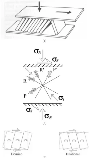
The analogy with a bookshelf type mechanism (Fig. 1) to describe the antithetic accommodation of deformation provoked by direct shear, or quasi-simple shear (Mandl, 2000), was initially proposed byMandl (1987). Differently from the ideal simple shear, in direct shear, the parallel rock boundaries, where a constant normal stress is applied, are allowed to dilate or contract perpendicularly to the shear direction.Mandl (1987)analyzed the stress conditions that would lead to the above mentioned mechanism using conventional graphical representation of Mohr circles. Subsequently,Mandl (1988)presented a number of natural examples where the mechanism would be applicable. Recently, Mandl (2000) extended the discussion of the problem by giving it a role in the formation and analysis of other structures such as shear joints, parallel faults produced
by horizontal extension and inversion of normal and reverse faults.
Mandl (2000) distinguished two possible styles of accommodation of deformation by the proposed bookshelf mechanism (Fig. 1). The domino style is associated with an extension parallel to the direction of shear and with a contraction perpendicular to it. The dilational style, in contrast, has a contraction in the shear direction and an extension normal to this direction. In the domino style, the formation of antithetic R0(Riedel) faults occurs, whereas in
the dilational style, faults known as P0type are formed (also
antithetic,Fig. 1).
Independent of style, the analogy, as originally proposed, corresponds to a bookshelf with books, vertically disposed, above which a horizontal rigid board is placed (Fig. 1). Horizontal displacement of the board could in principle simulate the effect of shear on a block located between parallel faults or even strata of different competence on the limb of a flexural slip fold (Mandl, 1988).
0191-8141/$ - see front matterq2004 Elsevier Ltd. All rights reserved. doi:10.1016/j.jsg.2004.03.002
www.elsevier.com/locate/jsg
* Corresponding author.
Fig. 1shows that the direction given to the displacement of the upper board is not followed by the direction of sliding between the books. In fact, they rotate, an essential feature in order to accommodate the deformations. The surfaces of contact between the books represent the parallel antithetic faults. The books represent the blocks (lithons) separated by the faults. The analogy, in this sense, may appear rather exaggerated, as the books are rigid whereas real rock blocks are relatively more deformable. This, however, does not render it invalid qualitatively. The presence of rotations in the mechanism can only be explained if one assumes the existence of different values for shear stresses in the vertical and horizontal planes, which will then give rise to non equilibrated resultant moments. However, it is well known from classical mechanics that shear stresses in perpendicu-lar planes are of equal magnitude (Cauchy stresses principle) and, as a consequence, the stress tensor is symmetric (Mase and Mase, 1992).
The authors argue therefore that one cannot interpret, in a theoretically consistent way, the bookshelf mechanism by using classic continuum mechanics, as it presupposes equal
shear stresses in perpendicular planes, a fact that is incompatible with rotations. However, the generalized continuum mechanics of Cosserat (Cosserat and Cosserat, 1909) provides the necessary features to analyze the problem:
(a) independent rotational degrees of freedom in addition to the classic translational ones (see Appendix A, item A1);
(b) shear stresses on perpendicular planes which are not necessarily equal, but which are equilibrated through the introduction of new quantities, the so-called moment (or couple) stresses (see Appendix A, item A2).
As a consequence, parameters with dimensions of length appear in the stress – strain relationships and/or strength criteria. This fact brings with it a scale dependency effect, which is a well-known factor for geological materials in general (Jaeger and Cook, 1979).
The pioneer work systematizing the generalized mech-anics was made in France byCosserat and Cosserat (1909). The idea of an extension of the classic continuum, one which incorporated independent rotational degrees of freedom, as well as non symmetric shear stresses and couple stresses, had already been suggested in the nine-teenth century by important theoreticians in continuum mechanics (Poisson, 1842; Cauchy, 1850; Saint Venant, 1869; Voigt, 1887). The theory remained practically forgotten until the mid sixties when it was reexamined, receiving a great theoretical impulse (Kro¨ner, 1968). The number of foreseen applications was, however, relatively limited. One of the main suggestions at that time came from
Mindlin (1963), for studies on stress concentrations around voids.
Lippmann (1969) pioneered the use of the theory to describe yielding/failure of granular materials. Chappell (1979), amongst others, proposed its use to describe the mechanics of fractured media. The repercussion of the latter work came years later through a publication by Besdo (1985). In these works, a correct modelling of the mechanical behaviour requires that the material points have independent rotational degrees of freedom. This is in fact, what distinguishes the kinematics of the Cosserat generalized mechanics from the classical mechanics (Appendix A, item A1).
In the 1980s, a growing interest in generalized mechanics occurred, starting with the work of Mu¨hlhaus and Vardoulakis (1987), who proposed applications of the theory to the modelling of localization of plastic defor-mations in brittle materials. This problem is dependent on the scale of the microstructure (grains) and a clear independence was demonstrated between the rotations in the interior of the localization zone and the rotations outside this zone.
In relation to applications in geology, it appears thatBiot
(1967) was the first to use the Cosserat mechanics. Biot studied the problem of buckling of multilaminated, anisotropic rocks (e.g.Price and Cosgrove, 1990) and its relation with formation of folds and, in particular, of kink bands. His results, when using classic continuum, related the critical load causing folding to a zero fold wave length, which is, clearly, a physical inconsistency of the mathematical theory. This inconsistency could be corrected through the introduction of the Cosserat mechanics whereby the rock laminae were assigned thickness and flexural strength.
This work presents an analysis of the stresses involved in the bookshelf mechanism by using the graphical construc-tion of the Mohr circle, as it has been done in the literature (seeMandl, 1987; 1988, 2000). However, the approach used differs from previous workers in that use is made of the mechanics of Cosserat generalized continua, which is thought to be a more adequate, if not a necessary basis, for the correct treatment of the problem. A description of a specific geological problem is presented, which is then followed by an analysis using Mohr circles adapted for Cosserat generalized continua. The Appendices give the basic elements for the understanding of the mechanics of Cosserat generalized continua and the adaptation of Mohr circles for such media.
2. The problem
The problem to be analyzed here (Fig. 2) is a version of the bookshelf mechanism that occurs under conditions of crustal extension at the surface. This problem was introduced byRamsay and Huber (1987), from whereFig. 2was extracted.
The decision to analyze this specific case instead of the direct shear cases treated by Mandl is because it has a well defined boundary condition: the free surface, represented by a horizontal plane, is the Earth’s surface, where the tractions are identically zero. Such a boundary condition, with values known for both stress components, normal and shear, does not exist in the analyses presented by Mandl.
The stress conditions at a point on the surface are illustrated on Fig. 3. One can notice that in a horizontal plane,
sV¼sHV¼0, where sV is the normal stress component (vertical) andsHVthe shear stress component. On a vertical plane,sVandsVHare not necessarily zero. It should be noted that sHV–s
VH is mechanically sound when using the Cosserat generalized mechanics (see Appendix A).
In the adopted notation, the first subscript for the stresses represents the direction and, the second, the plane of action of the component. Such ordering of subscripts is contrary to what is generally found in texts dedicated to the stress analysis in classical continua (Jaeger and Cook, 1979). The reason for this is that the order becomes relevant as a function of the asymmetry of the stresses in the Cosserat generalized continua. The ordering appears as a conse-quence of theoretical consistency when, in the process of
derivation, energy methods such as the Principle of Virtual Work (Appendix A, item A3) are used (Germain, 1973; Figueiredo, 1999).
A schematic illustration of the rigid blocks (assumed to be rectangular) formed by antithetic faults is shown onFig. 3. Their dimensions are represented by a baseband a height
h. The introduction of block dimensions to the problem is another distinctive feature of the generalized mechanics in relation to the classic mechanics. In the example, the block dimensions (and shape) will make it possible to take into consideration an additional strength mechanism, besides the conventional Mohr – Coulomb one, which is related to the friction between blocks (Jaeger and Cook, 1979).
This mechanism involves ‘rolling friction’ (Nascimento and Teixeira, 1971; Fadeev and Kuzevanov, 1993) and is related to the toppling (rotation) of the blocks. The equation describing it is (see Appendix C):
sS¼sNtanw; ð1Þ
where sS is the shear stress, sN is the normal stress and
w¼tan21ðb=hÞis the ‘rolling friction’ angle.
Eq. (1) provides, therefore, the value of the horizontal component of shear necessary to topple (rotate) a rectangu-lar block, having widthband heighth, subjected to a normal vertical stress sN. It has a similar form to the classical Mohr – Coulomb equation describing the shear strength:
sS¼sNtanf; ð2Þ
where f is the classical friction angle and the remaining symbols have the same meaning as in Eq. (1).
Additionally, a cohesive term could be added to both Eqs. (1) and (2). Furthermore, due to the non-existence of friction under tension (Jaeger and Cook, 1979), it is usual to add a tension cut-off to Eq. (2):
sN#T; ð3Þ
whereTis the tensile strength of the medium.
3. Graphical stress analysis
conclusions of the analysis (as will be explained in the sequence). It ultimately means that up to this point in the analysis it is not necessary to consider any intrinsic structure of the material. Such structure will appear later due to faulting.
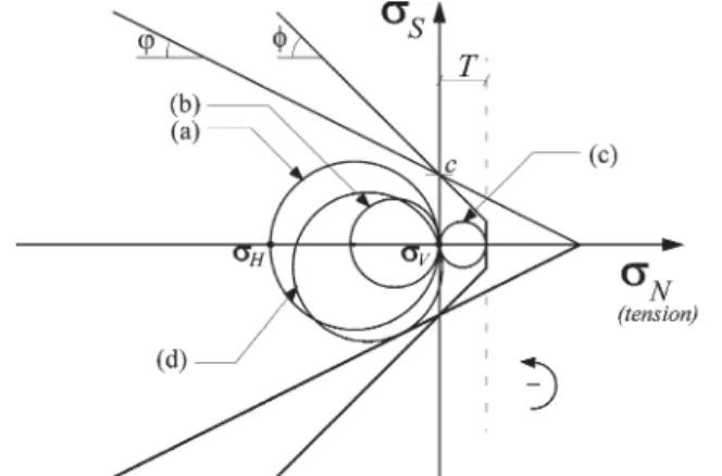
In this case, vertical and horizontal planes will be initially the principal planes, and a Mohr circle for a point on the surface would be plotted with its center on the normal stress axis (circle ‘a’ inFig. 4), as usual. Because this Mohr circle has its center on the normal stress axis, the shear stresses of diametrically located points, which correspond to the stresses on two perpendicular planes, are equal.
Fig. 4shows the failure conditions through sliding, using the classical Mohr – Coulomb strength envelope (with a tension cut-off; Eq. (3)) together with a strength envelope for toppling (rotation) given by the strength criterion for rolling friction (represented by Eq. (1) with a cohesive term added). The crustal extension at the point analyzed can be represented in the Mohr space by a progressive reduction of
sH(hypothetically assumed to be initially compressive) and Fig. 2. Bookshelf mechanism in crustal extension (Ramsay and Huber, 1987): (a) and (b) mechanism; (c) illustration of an outcrop.
Fig. 3. State of stress for a point on the surface.
by maintaining the stress vector on the horizontal plane (free surface) equal to zero. This means that Mohr circles always pass through the origin.
If the medium behaved as a classical continuum, the point would be taken initially to the state of stresses represented by circle (b). Failure occurs when the circle touches the tensile strength envelope, as does circle (c), and would generate vertical failure planes. For the stress path followed, there is no possibility of shear failure of the Mohr – Coulomb type. This is because the diameter of the circle decreases constantly whilst the principal stresses are compressive. The diameter of the circle is only able to increase under tension where such criterion is no longer valid because of the absence of friction, already pointed out previously (Jaeger and Cook, 1979). Therefore, if it is accepted that the medium behaves as a classical continuum, the only explanation for the occurrence of failure by extension on the Earth’s surface is the presence of tensile stresses. The occurrence of such tensile stresses, however, has not been supported either by experimental rock mechanics (e.g. Amadei and Stephansson, 1997) or by theoretical models (Sheorey, 1994). In addition, it is not possible to explain the observed in-situ rotations.
There remains therefore no other alternative but to abandon the axiom of symmetry in the classical stress tensor and to allowsVH–0, positive in the case ofFig. 4and having the effect of a counter-clockwise couple (the sign convention for the Mohr circle is presented in Appendix B). At this stage, the framework of the generalized mechanics of Cosserat becomes convenient as it incorporates asymmetric shear stresses. Additionally, the other distinctive features of this mechanics (mentioned in Section 2) are also present. The internal structure represented by the blocks and its independent rotations are clearly noticed. In the Cosserat generalized mechanics, this structure will imply the existence of an intrinsic scale, which appears as characteristic lengths in the stress–strain relations and strength criteria, as shown in Appendixes A (item A4) and C, respectively.
It should be noted thatsHVis zero due to the boundary condition (free surface), and thatsVH¼22sa;wheresa¼ ðsHV2sVHÞ=2:sais the so-called anti-symmetric stress, one that quantifies the difference between shear stresses on perpendicular planes (see Appendix A). This implies that the circle, according to the Cosserat theory, will translate perpendicularly to the normal stress axis a distance equal to halfsVH(sVH=2¼
sa), in the sense of negativesS. This leads to the situation represented by circle (d), which satisfies the boundary condition at the free surface, similarly to the previous classical stress circles. Circle (d) is able to displace, though always passing through the origin (becausesV¼0), until it touches the Mohr–Coulomb envelope. However, it seems that blocks, generated by antithetic faults, can become unstable before this occurs, as shear failure surface, having the classic ^ðp=42f=2Þ inclination to the vertical, are not
generally observed in these situations. In fact, failure may
occur when circle (d) reaches the rolling friction envelope having an inclination anglew(see Section 2).
InFig. 4, the Mohr–Coulomb envelope is plotted with a friction angle of 458. This value should not be considered high
as it is known that sliding can be very dilatant for low levels of normal stress (e.g.Goodman, 1976). In contrast, the rolling friction angle is given a slightly exaggerated value of 358, so
that the respective envelope plots inside to the Mohr– Coulomb envelope for compressive normal stresses. For this rolling friction angle, the blocks inFig. 3have a width/height ratio of 0.7. More slender blocks could be generated by this antithetic failure mechanism, corresponding to lower values of
w. Therefore, failure could be even more likely than implied by
Fig. 3(because the respective envelope would lie below what was illustrated there). Thus, by admitting the existence of an a priori, intrinsic structure for the medium, the possibility of a rotational failure (toppling of blocks) becomes plausible as an alternative mechanism. This type of rotational failure causes the appearance of associated faults (in this case antithetic), in the same way as conventional faults are produced by simple shear.
It is remarkable that for an antithetic failure to occur, a minimal decrease in sH is required, in contrast to the classical failure mode where all planes but the horizontal must be under tensile stresses. Also, it is not necessary for a contraction of the circle to occur, as failure can be reached through its simple vertical translation. In the present analysis, a decrease of sH was adopted, consistent with crustal extension, which is evident from plate tectonics studies (e.g.Mattauer, 1973).
There are very few planes under tension as a result of the proposed mechanism and even those that do experience tensile stresses, when compared with the classical values, are of very small magnitude. The only way to generate classical shear failure would be to increase the vertical stress, concomitant with horizontal extension. This is clearly not possible in the case under analysis, as a point on the surface is being considered. As a resultsVremains equal to zero.
It could be argued that faults are nucleated in the crust at depth, i.e. with a positive value ofsV. This would make the classical shear mechanism more plausible, but this depth factor in no way excludes the possibility of an antithetic faulting, as demonstrated in several seismic profiles of sedimentary basins (e.g.Mandl, 1988). Geological evidence of the type shown in Fig. 2b, however, given by recent sediments accumulated in sub-basins between toppled blocks, seem to contradict the possibility that the antithetic faults were formed in depth (e.g. on the limbs of a flexural slip fold), subsequently being brought to the surface by denudation.
4. Conclusions and suggestions for additional applications
This analysis takes into consideration distinct strength envelopes for the two possible failure mechanisms; one involving rotation (antithetic faulting) and the other sliding. The main features of the theory of the generalized Cosserat continuum have been described with particular reference to those pertinent to the problem of the bookshelf mechanism. The bookshelf mechanism can be interpreted in a simple way by using the mechanics of generalized Cosserat continua. By using this theory that takes into account rotations and the anti-symmetric portion of the stress tensor
sa
, it is possible to explain the formation of antithetic faults. This type of faulting is related to rolling friction, which implies a lower strength when compared with sliding related faulting. By using the Cosserat theory it is not necessary to appeal for the unlikely tensile stresses in practically all planes, as required for classical failure mechanisms. Furthermore, through the use of Mohr circles and a Cosserat continuum, the analyses provides a way to incorporate rotations and sa
(i.e. ðsHV2sVHÞ=2), both of which are responsible for the development of rotational antithetic faults. This is not possible when using the classical continuum, which does not incorporate these quantities.
Several problems in structural geology can be investi-gated under the framework of the theory of Cosserat generalized continua. An example is the problem of folding of multilaminated media as presented initially by Biot (1967) and complemented by Latham (1985a,b). Other problems, all of them involving rotations, include the analysis of the simple shear tectonics and its anastomosed patterns (in particular, the genesis of Riedel type fractures, R and R0), sigmoidal veins (Figueiredo and Vargas, 2001),
the formation of kinkbands, etc. This paper aimed to demonstrate that Cosserat mechanics is not only appropriate for analysis of the bookshelf mechanism, but also for all geological processes that involve rotational antithetic mechanisms of deformation.
Acknowledgements
Part of this research work was carried out during the preparation of a Ph.D. thesis by the first author. PICD-CAPES-UFOP/Brazil is acknowledged for financial sup-port. J. Cosgrove, an anonymous reviewer and the editor J. Hippertt are thanked for their valuable comments and suggestions.
Appendix A. The mechanics of 2D Cosserat generalized continua
In its classic description, a continuum is a continuous distribution of particles, which are represented geometri-cally by a material point having cartesian coordinates xi (i¼1 – 3), with reference to a fixed system of orthogonal
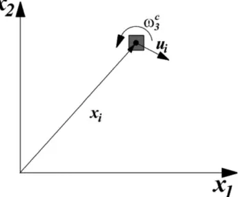
axes and characterized kinematically by a displacement vector ui. In contrast, in the generalized continuum description, each point is seen as a particle having small dimensions, which is itself a small continuum around that point (Fig. A1). The kinematical characterization of the point or of the material particle strictu sensu, requires a refinement in relation to the classical continuum. The complexity of this refinement gives rise to the differences between the various generalized theories that have been proposed (Kro¨ner, 1968).
In the Cosserat theory, the pioneer amongst the generalized theories, the material particle is rigid and has microrotations vc
i as additional degrees of freedom to ui. This way, in such a continuum, the particle will have the degrees of freedom of a rigid body positioned in xi. The gradients of microrotations, named curvatures, are added to the classical components of strain constituting a non-symmetric tensor as shown in item A2 of this Appendix.
Through the Principle of Virtual Work (Chou and Pagano, 1967; Germain, 1973), it is possible to conjugate energetically the kinematical measures of the generalized continuum to their corresponding statical quantities, as briefly discussed in item A3 of this Appendix. As a result, the couple stress tensor, which is conjugate to the curvatures, and the force stress tensor of Cosserat, analogous to the classic stress tensor (although non-symmetric), can be obtained. This asymmetry is particularly important to explain the bookshelf mechanism.
With the above mentioned static-kinematic refinements, the Cosserat theory allows representation of flexural and torsional effects, which are not present in the classic continuum. In contrast, the dimensions of the material particle, here denominated characteristic length, introduce a dependence on its underlying basic structure in the constitutive description (Jaeger and Cook, 1979).
In the particular case of rock masses, the rigid material
particles of the Cosserat continua are able to represent the blocks formed between pre-existing geological disconti-nuities. This is so because these blocks are in general more rigid than the entire rock mass, where the deformability is concentrated on the interfaces (Goodman, 1976). In the sequence, a brief description of the kinematics of a 2D Cosserat continuum, restricted to small strains, is presented. A few remarks will be made about the constitutive relations for an isotropic linear elastic material and pertinent strength criteria.
A1. Kinematics
Consider a plan of deformations parallel to Cartesian orthogonal axes (x1,x2).xi(i¼1, 2) are the coordinates of a material point in a 2D Cosserat continuum. A rigid microparticle is associated with each point and, in the center of mass of the particle, a new local rigid cartesian coordinate system is located. During the deformation process, each particle moves ui and may suffer a rotation
vc
3(Fig. A1). The subscript indicates that the rotation occurs around the axisx3, normal to the plan of deformations, and the superscript is used to distinguish the Cosserat micro-rotations from the conventional macromicro-rotations, which are in principle independent. This fact is crucial for the develop-ment of Cosserat theory, where the rotations bear no interdependence with the translational degrees of freedom, as occurs with the macrorotations of the classic mechanics.
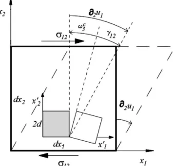
The strain quantities in a Cosserat continuum aregijand
ki, named, respectively, ‘relative strains’ (non-dimensional) and ‘curvatures’ (with dimensions of inverse of length), which are defined in 2D as:
g11¼›1u1; g12¼›2u1þv
c 3;
g22¼›2u2; g21¼›1u22vc3;
k1¼›
1v c
3; k2¼›2v c
3 ðA1Þ
where›i(·) represents a gradient of (·) in the direction ofi. One can demonstrate (Figueiredo, 1999) that these quantities are objective, i.e. they are invariant with respect to rigid body movements, and can be used in the formulation of constitutive laws (Mase and Mase, 1992). Asg12–g21;it is noticed thatgijis non-symmetric in the non-trivial case where
vc
3–0:It should be noted also that the symmetric part ofgij,
gðijÞ ¼ ðgijþgjiÞ=2;coincides with the classic strain tensor,eij, while its anti-symmetric part g½ij¼ ðgij2gjiÞ=2; is the difference between the macrorotations,V12¼v3¼ ð›2u12
›
1u2Þ=2; and the Cosserat microrotations vc3 (i.e.
g½21¼v32vc3). An illustration of the kinematics rep-resented by the expression ofg12is shown inFig. A2.
The particular case, in which the Cosserat microrotations coincide with the rigid body macrorotations, i.e. whenv3¼
vc
3; was considered by Mindlin (1963) and used by Biot
(1967). This case is important only where the medium remains elastic. In the plastic domain, micro and macro-rotations can be significantly different (Cosserat and Cosserat, 1909; Mu¨hlhaus and Vardoulakis, 1987), as is generally the case in structural geology and particularly in the analysis of bookshelf mechanisms.
A2. Statics
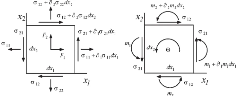
A 2D Cosserat continuum contains six static quantities, energetically conjugate (through the Principle of Virtual Work) to the kinematic quantities defined in item A1. Therefore, besides the conventional stress tensor sij, hereafter denominated force stress tensor, there are two additional components of couple (or moment) stressesmi¼
m3i(i¼1, 2), with dimensions of moment by units of area. In a plan element of infinitesimal dimensionsdx1anddx2 parallel to the coordinate axes (Fig. A3), it is assumed that an average value can be adopted for the distribution of force stress vectors and couple stresses on their faces. Moreover, it is also possible to neglect the terms higher than the first order, in a Taylor series approximation of the stress components on a face xiþdxi; as function of those on facexi. By stating the equilibrium of forces according to the directions x1 and x2, the following relationships between force stresses in a Cosserat continuum are obtained:
›1s11þ›2s12þF1¼0 ðA2aÞ
›1s21þ›2s22þF2¼0 ðA2bÞ
whereFiare body forces. In analogy, by stating the moment equilibrium in relation to the central point of the element
one has:
›1m1þ›2m2þ ðs212s12Þ þQ¼0 ðA3Þ
whereQis a body moment.
From Fig. A3 and the above mentioned moment equilibrium relations, we note that the shear components do not vary between a face in xi and its neighbor at
xiþdxi: That does not mean, however, that their non-uniformity was disregarded. What happens is that the moments of the first degree terms, in the Taylor series for such components, would be infinitesimals of higher order and, therefore, would end eliminated. Physically, this can be understood as the existence of a higher gradient for couple stresses than for force stresses in the scale of an infinitesimal element.
In dynamic problems, inertia effects can be included in body forces and moments according to d’Alembert’s principle (Teodorescu, 1975). Eq. (A3) shows that where non-zero couple stress gradients occur, the shear stresses
s12 and s21 are not necessarily equal. One concludes therefore that the force stress tensorsijis, in general, non-symmetric, similarly to the tensor of relative deformation mentioned previously.
Symmetry will occur in the static case if and only if couple stresses, although present, are self-equilibrated (body moments can generally be disregarded), or when they are identically zero as in classical continuum. In dynamic problems, the microinertial effects included in body moments in Eq. (A3) can by themselves generate the asymmetry of force stresses.
The force stresses can be split into their symmetric,
sðijÞ¼ ðsijþsjiÞ=2;and anti-symmetrics½ij¼ ðsij2sjiÞ=2 components. Particularly, these components are denoted by
sð12Þ¼ ðs12þs21Þ=2¼ssands½12 ¼ ðs122s21Þ=2¼sa:
It should be noted that for the normal stresssðiiÞ ;siiand
s½ii;0:s
s
corresponds to the classical shear stresses and provokes only distortion of the material points.sa
, which is related to the couple stresses by the Eq. (A3), produces exclusively rotation (Fig. A4). The understanding of the way that each component acts on the deformation of the
generalized continuum, is important for formulation of strength criteria. These criteria must be specific for each failure mechanism.ssmay generate sliding whilesamay generate toppling (rotation).
It is remarkable that Ramsay (1967) had already noticed the ‘need’ of an asymmetry in the stress tensor. Even based in mechanically inconsistent concepts and apparently not aware of the generalized theory of Cosserat, that author suggested that part of the deviatoric tensor would ‘not be in equilibrium’, what was called by him the ‘disequilibrium component’ (Ramsay, 1967, p. 283). This is precisely the anti-symmetric portion of the shear stresses (sa
) that, as described previously, is responsible for the asymmetry of the force stress tensor of Cosserat. Perhaps, it was not by chance that Ramsay (1967) concluded the existence of this non equilibrated component, based on his perception that rigid rotations of points of the medium (microrotations) were commonly independent of the rigid body rotations (macrorotations,
V12 ¼v3 ¼ ð›2u12›1u2Þ=2) and would require the definition of associated stresses. What perhaps was not fully perceived by Ramsay (1967) is that there is no disequilibrium, but the existence of couple stresses that oppose the effect of anti-symmetric shear stresses. This is exactly what is expressed by Eq. (A3).
Fig. A3. Force and moment equilibrium for an infinitesimal element of Cosserat generalized continuum.
A3. Virtual Work Principle
In mechanics, displacements are concrete quantities, having a physical existence, while forces (and stresses) are postulated and abstract. It is therefore instructive to introduce and define the latter through the virtual work they produce under given virtual displacements. The proposition, in a general way, consists of obtaining the statics of the medium from the kinematics, through the Principle of Virtual Work (Chou and Pagano, 1967). When the kinematic description is refined, as in the case of generalized continua, it is natural that new static quantities are sought through its energetic dualities (conjugations), expressed in the Principle of Virtual Work (Germain, 1973). Used in this form, this principle constitutes a method through which it is possible to define, in a systematic way, the statics and the boundary conditions (Germain, 1973), justifying, for example, the appearance of the couple stresses in the Cosserat theory.
The application of the method starts by establishing the virtual work of the internal forces for the generalized medium. This virtual work has to be a quantity invariant with respect to rigid body motion (axiom of objectivity of the virtual work of internal forces;Germain, 1973). So the objective tensorsgijandkiwill be used in the expression of the virtual work. Specifically for the development of the current section, we will use the tensorial (indicial) notation (Chou and Pagano, 1967) with their usual conventions such as, for example, the implicit summation for repeated subscripts (Einstein’s convention). In the present work, due to the fact that only plane problems are being treated, the range of variation of the subscripts will bei,j¼1, 2. In indicial notation, the above mentioned tensors can be written asgij¼›juiþeij3vc3andki¼›ivc3;whereeij3is the permutation (or alternating) tensor in 2D (Chou and Pagano, 1967). It is assumed that the medium occupies a volumeV
with boundaryG. In this case, the virtual work of the internal forces (dWI) will be given by:
dWI¼ð
V
ðsijdgijþmidkiÞdV ðA4Þ
where the tensorial coefficientssijandmiare the introduced static variables, which are associated, in energy, with the adopted kinematics.
din Eq. (A4) indicates that the kinematic quantities are virtual. If kinematically admissible, i.e. satisfying the boundary conditions, these quantities do not interfere with the equilibrium (Chou and Pagano, 1967). Apart from that they are entirely arbitrary and by consequence independent. In the case of classic continuum, the only term present in the integrand would be the first. Rewriting Eq. (A4), consider-ing the definitions of the kinematic tensors, gives:
dWI¼ð
V
½sijð›jduiþeij3dv c
3Þ þ ðmi›idv c
3ÞdV ðA5Þ
and, therefore
dWI ¼ð
V
½sij›jduiþsijeij3dvc3þmi›idvc3dV
¼ð V
½sij›jduiþ2sadv c
3þmi›idv c
3dV ðA6Þ
where an equivalent form of the second term was used on the right hand side of the equality. This results from the definition given tosa
in item A2 that, in indicial notation, is
sa¼ 1
2eij3sij (Chou and Pagano, 1967). By applying the rules of differentiation of a product to the first and third terms of the integrand of Eq. (A6), or, what is the same, integrating by parts leads to:
dWI ¼ð
V
{½›jðsijduiÞ2›jsijdui þ2sadvc3
þ ½›iðmidvc3Þ2›imidvc3}dV ðA7Þ
By applying the Gauss – Ostrogradski divergence theo-rem (Chou and Pagano, 1967) to the first and fourth terms and putting dvc
3 in evidence in the third and fifth terms, gives:
dWI ¼2ð
V
›jsijduidV2ð
V
ð›imi22saÞdvc3dV
þð
GsijduinjdGþ ð
Gmidv c
3nidG; ðA8Þ
whereniis the unit normal vector pointed to the exterior of
G.
The form of the expression of virtual work of the internal forces, extended to a Cosserat continuum (Eq. (A4)), motivates further extension to quantify the virtual work of the external forces (dWE); for body forces (dWVE) and surface forces (dWGE):
dWVE ¼ð
V
FiduidVþð V
Qdvc
3dV; ðA9aÞ
dWGE ¼
ð
G
tiduidGþ ð
G
mdvc3dG; ðA9bÞ
dWE ¼dWVEþdWGE; ðA9cÞ
whereFiis a body force,tiis a surface traction,Qis a body moment, andmis a surface moment. This extension ofdWE
is due to the fact that in classical continuum, the existence of a stress tensor (a second order tensor) in the internal work leads to the appearance of force vectors (first order tensors) in the external work. By analogy, existing vector of couple stresses in the internal work, one scalar quantity (body and surface moments, zero order tensors) in the external work should appear.
external forces on any assumed, equally admissible, kinematic fields is equal to the work performed by the internal forces, i.e.dWI ¼dWE.
This is the direct statement of the principle. The inverse statement, which is used in the present work, establishes that, if for the static fields assumed,dWI¼dWE, consider-ing all admissible kinematic virtual fields, then the former (static fields) will be statically admissible. This inverse statement allows the obtaining of equilibrium equations and the natural boundary conditions as follows.
A mathematical statement of the principle (dWI ¼dWE), through Eqs. (A8), (A9a) and (A9b), is therefore:
2ð
V
›jsijduidV2ð
V
ð›imi22saÞdvc3dV
þð
GsijduinjdGþ ð
Gmidv c 3nidG
¼ð V
FiduidVþ ð
V
Qdvc
3dV
þð
GtiduidGþ ð
Gmdv c
3dG; ðA10Þ
As the variations ofuiandvc3in Eq. (A10) are arbitrary and independent, it is possible to equate directly their coefficients and transform it into two new equations; the first common to the classical continuum and the second specific to the generalized Cosserat continuum, which are:
2ð
V
›jsijduidVþð
GsijduinjdG
¼ð V
FiduidVþ ð
GtiduidG
; ðA11aÞ
and
2ð
V
ð›imi22saÞdvc3dVþð G
midvc 3nidG
¼ð V
Qdvc
3dVþ ð
Gmdv c
3dG ðA11bÞ
By reorganizing the terms, we obtain:
ð
V
{ð›jsijþFiÞdui}dVþð G
½ðti2sijnjÞduidG¼0ðA12aÞ
and
ð
V
{ð›imi22saþQÞdvc3}dV
þð G½ðm
2miniÞdvc3dG¼0 ðA12bÞ
These equations will only be satisfied for arbitrary variations if, simultaneously in each one of them, the integrands of the volume and surface integrals are zero. So
the equilibrium equations
›jsijþFi¼0; ðA13aÞ
and
›imi22saþQ¼0; ðA13bÞ
are obtained, which are equivalent to Eqs. (A2a), (A2b) and (A3) written in indicial notation, and the natural boundary conditions
ti¼sijnjðCauchy stress equation applied toGsÞ ðA14aÞ
and
m¼mini: ðA14bÞ
To evaluate the integrals in the equations above, it is necessary to assume that boundary G is defined in complementary parts Gu, Gv, Gs and Gm. The natural boundary conditions in Eqs. (A14a) and (A14b) are prescribed on Gs and Gm, respectively. The essential boundary conditions related touiandvc3 are prescribed on
GuandGv, respectively.
A4. Stress – strain relationships
The equations for the linear elastic isotropic behaviour of a 2D Cosserat continuum involve four parameters. They can be written as (Teodorescu, 1975):
l; G; GcandB¼2Gl2;
wherelandGare analogous to Lame’s classical parameters (Jaeger and Cook, 1979), Gc is an anti-symmetric (or rotational) shear modulus,Bis a flexural modulus (having dimension of force) andlis the characteristic length of the medium.
The stress – strain relations is stated as:
sij¼lekkdijþ ðGþGcÞgijþ ðG2GcÞgji; ðA15aÞ
and
m3i¼mi¼Bki: ðA15bÞ
Eq. (A15a) can be rewritten as:
sij¼lekkdijþ2Geijþ2Gcg½ij; ðA15cÞ
in function of the symmetric and anti-symmetric parts of the relative deformations defined in item A1 of this Appendix. It can be noted that two new parameters appear: Gc, which relates the anti-symmetric parts of the force stresses and the relative strains andl, which introduces flexural effects (and by consequence scale effects) in the medium, indirectly measuring the dimensions of its internal structure. In this case, where the material is isotropic, only one characteristic length exists.
strength criteria represent the additional failure mechanisms induced by the anti-symmetric force stresses and by couple stresses. For the analysis of the bookshelf mechanism focused on in this paper, a criterion representing failure by rotation was given by Eq. (1).
Appendix B. The 2D Mohr circle for Cosserat continuum
In the generalized Cosserat continuum, like in the classical continuum, the force stresses in 2D can be represented graphically by a circle in the Mohr stress space, i.e. the space of normal stresses versus shear stresses (sN£sS). This type of representation is derived in the present Appendix.
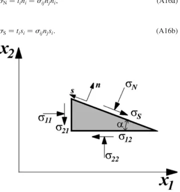
Fig. A5 shows a free body diagram where the components of force stresses are indicated. The faces of the diagram are oriented perpendicular to the coordinate axes and to a unit vectornimaking an anglea(arbitrary) to the x axis.This unit vector has components ðn1;n2Þt;ðcosa;senaÞt, while the components of a vector
si, parallel to the plane, areðs1;s2Þt;ð2sena;cosaÞt: By imposing an equilibrium of forces along the coordinate axes, it is possible to determine the respective components of the vector of force stresses,ti, in the plane normal toni(hereafter designated by planea), knowing that
ti¼sijnj. The projection of ti over ni and si will give, respectively, the normal (sN) and shear (sS) stress components in planeaas:
sN¼tini¼sijnjni; ðA16aÞ
sS¼tisi¼sijnjsi: ðA16bÞ
These expressions, in extended form, are:
sN¼s11cos2aþs22sen2a
þ ðs12þs21Þsenacosa; ðA17aÞ
sS¼s21cos2a2s12sen2a
þ ðs222s11Þsenacosa; ðA17bÞ
or, in terms of 2a:
sN2 1
2 s11þs22
¼ 12 s112s
22
cos2aþ 12s12þs21sen2a; ðA17cÞ
sS2 12 s212s12
¼ 12 s222s11
sen2aþ 12 s12þs21
cos2a: ðA17dÞ
Squaring both sides and adding Eqs. (A17c) and (A17d) we arrive at the equation of a circle in the plane (sS,sN):
sN2sm
2
þsSþsa
2
¼ s112s22 2
2
þ s12þs21 2
2
; ðA18Þ
where sm¼ ðs11þs22Þ=2 and sa¼ ðs122s21Þ=2 are, respectively, the average normal stress and the anti-symmetric shear stress. Therefore the locus of the states of force stresses in 2D represented on plane is a circle, as in the classical continuum. The difference is that its center undergoes a translation 2sa in a direction perpendicular
to the axis of normal stresses, being therefore located in the point of coordinates (sm,2s
a ).
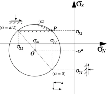
Fig. A6 shows a Mohr circle for the state of stress represented in Fig. A5. In the adopted convention, the tensile stresses are positive. Therefore, the shear stresses (symmetric and anti-symmetric) are plotted as positive when producing clockwise rotating couples, i.e. dextral shear in geological nomenclature (see Chou and Pagano, 1967, section 1.5).
All the elegant graphical solutions of structural geology problems obtained with the Mohr circle in the classical continuum (Mandl, 2000), are possible in the Cosserat continuum with minimal adaptations. Values and orientations of principal stresses, which may not be mutually perpendicular and may not even exist, if the value ofsa
is such that the circle does not intercept the sN axis, can be determined by procedures as those used in classical continuum. The same applies to the determination of maximum and minimum normal stresses (which no longer coincide with the principal stresses) and to the calculation of the maximum shear stress. The concept of pole, or origin of planes (point P inFig. A6), is equally valid in the graphical construction.
Fig. A7shows the effect of the anti-symmetric part of the shear stresses in inducing failure in a point of the medium. Through the displacement in a direction perpendicular to the normal stress axis, the circle may become tangent to one strength envelope without increasing its diameter. This corresponds to an exclusive increase of the anti-symmetric part of the stresses, which, as mentioned before, is related to rotations (as occurs in the bookshelf mechanism).
For three-dimensional states of stresses, the graphical representation cannot be given by a combination of three circles in the planesS£sNas in classical continuum (e.g.
Jaeger and Cook, 1979). The representation for the total (non-symmetric) stress tensor (Unterreiner, 1995) is given by more complex curves (planar sections of quadric surfaces), which reduces its applicability.
Nikolaevski (1996) introduced the couple stresses, together with force stresses, in the equilibrium of moments in the free-body diagram of Fig. A5. By doing so, the
pertinent space of stresses becomes three-dimensional (sS£sN£m) and its projection on a plane takes to an elliptical form for the graphical representation of the 2D stress tensor. In the authors’ opinion, the implications of this form, as well as of the possible variants of Cosserat Mohr circles, in the analysis of geological structures, deserves appreciation.
Some works (e.g. Lister and Williams, 1983; Means, 1983; De Paor and Means, 1984; Bobyarchick, 1986) involve the use of Mohr circles that may not be centered in the abscissa axis. These are circles for displacement or velocity gradients, which are non-symmetric second order tensors, similar to the force stress tensor in the Cosserat theory. These circles have been described byPrager (1961)
and are not the same as the Mohr circles for strain quantities of Cosserat continua, described in item A1. In the Cosserat mechanics, rotations are independent of displacements. In contrast, for the above mentioned displacement gradients, rotations are their anti-symmetric portion and, as a consequence, dependent on them. These circles have been utilized in the kinematic analysis of shear zones (Simpson and De Paor, 1993). They are not able, however, to take into account the independence of the rotations in the interior of the shear zones in relation to rotations in the remaining medium (Mu¨hlhaus and Vardoulakis, 1987). This is only possible by using Cosserat Mohr circles for strain.
Appendix C. A strength criterion for rolling friction: toppling of blocks
Consider rectangular blocks ABCD, with heighth, width
b and unit thickness perpendicular to their plane, as illustrated inFig. A8. Assume that a normal stresssNand Fig. A6. Mohr circle for a 2D Cosserat generalized continuum.
Fig. A7. Failure produced by anti-symmetric stresses.
a shear stresssSact on the horizontal planes, according to
Fig. A8, and that there is cohesion available in all vertical planes, between adjacent blocks. The moment equilibrium for a given block in the medium, relative to the point A, is: X
MA¼ ðsSbÞh2ðchÞb2ðsNbÞb¼0;
whereSMAis the summation of non zero moments of the various forces in relation to point A. Simplifying the above expression gives:
sS¼sNðb=hÞ þc:
By callingb=h¼tanw, we have:
sS¼sNtanwþc; ðA19Þ
wherewdenotes an angle representative of the slenderness of the blocks and is defined as the rolling friction angle. Eq. (A19) represents the required shear stress for the blocks to topple (roll), and is analogous to Eq. (1) with a cohesion term included.
References
Amadei, B., Stephansson, O., 1997. Rock Stress and its Measurement, Chapman and Hall, London.
Besdo, D., 1985. Inelastic behavior of plane frictionless block-systems described as Cosserat media. Archive of Mechanic 37, 603 – 619. Biot, M.A., 1967. Rheological stability with couple-stresses and its
applications to geological folding. Proceedings Royal Society of London A2298, 402– 423.
Bobyarchick, A.R., 1986. The eigenvalues of steady flow in Mohr space. Tectonophysics 122, 35 – 51.
Cauchy, A.L., 1850. Me´moire sur les syste`mes isotropes de points mate´riels. Me´moire de l’Acade´mie des Sciences, Paris, 22.
Chappell, B.A., 1979. Load distribution and redistribution in discontinua. International Journal of Rock Mechanics and Mining Sciences and Geomechanics Abstracts 12, 265– 270.
Chou, P.C., Pagano, N., 1967. Elasticity: Tensor, Dyadic and Engineering Approaches, Dover Publications, New York.
Cosserat, E., Cosserat, F., 1909. The´orie des Corps De´formables, Hermann et Fils, Paris.
De Paor, D.G., Means, W.D., 1984. Mohr circles of the first and second kind and their use to represent tensor operations. Journal of Structural Geology 6, 693– 701.
Fadeev, A.B., Kuzevanov, V.V., 1993. Strength of regularly jointed media. In: Pasamehmetoglu, A.G., et al. (Eds.), Proceedings of Assessment and Prevention of Failure Phenomena in Rock Engineering, Balkema, Rotterdam, pp. 175– 179.
Figueiredo, R.P., 1999. Rock mass modelling as Cosserat generalized continuous media (in Portuguese). PhD. thesis, Civil Engineering Department, Pontifı´cia Universidade Cato´lica do Rio de Janeiro, Rio de Janeiro, Brazil.
Figueiredo, R.P., Vargas, E.A., 2001. Sigmoidal veins: a model of its geometry/origin based on the Cosserat generalized continuum mech-anics (in Portuguese). In: SBG—Brazilian Geological Society (Eds.), Proceedings of the Second International Symposium on Tectonics of the Brazilian Geological Society, Recife, Brazil, pp. 205– 208. Germain, P., 1973. The method of virtual power in continuum mechanics—
part 2: microstructure. SIAM Journal of Applied Mathematics 25, 556– 575.
Goodman, R.E., 1976. Methods of Geological Engineering in Discontinu-ous Rocks, West Publishing, St. Paul.
Jaeger, J.C., Cook, N.G.W., 1979. Fundamentals of Rock Mechanics, 3rd ed, Chapman and Hall, London.
Kro¨ner, E. (Ed.), 1968. Mechanics of Generalized Continua. Proceedings of IUTAM Symposium, International Union of Theoretical and Applied Mechanics, Springer-Verlag, Berlin.
Latham, J.P., 1985a. The influence of nonlinear materials properties and resistance to bending on the development of internal structures. Journal of Structural Geology 7, 225– 236.
Latham, J.P., 1985b. A numerical investigation and geological discussion of the relationship between folding, kinking and fracturing. Journal of Structural Geology 7, 237– 249.
Lippmann, H., 1969. Eine Cosserat – Theorie das plastischen Flie(ens. Acta Mechanica 8, 255 – 284.
Lister, G.S., Williams, P.F., 1983. The partitioning of deformation in flowing rock masses. Tectonophysics 92, 1 – 33.
Mandl, G., 1987. Tectonic deformation of rotating parallel faults—the ‘bookshelf’ mechanism. Tectonophysics 141, 277– 316.
Mandl, G., 1988. Mechanics of Tectonic Faulting, Elsevier, Amsterdam. Mandl, G., 2000. Faulting in Brittle Rocks—An Introduction to the
Mechanics of Tectonic Faults, Springer-Verlag, Berlin.
Mase, G.E., Mase, G.H., 1992. Continuum Mechanics for Engineers, CRC Press, Boca Raton.
Mattauer, M., 1973. Les De´formations des Mate´riaux de l’E´corce Terrestre, Hermann et Fils, Paris.
Means, W.D., 1983. Application of Mohr-circle construction to problems of inhomogeneous deformation. Journal of Structural Geology 5, 279– 286.
Mindlin, R.D., 1963. Influence of couple-stresses on stress concentrations. Experimental Mechanics 3, 1 – 7.
Mu¨hlhaus, H.-B., Vardoulakis, J., 1987. The thickness of shear bands in granular materials. Ge´otechnique 37, 271– 283.
Nascimento, U., Teixeira, H., 1971. Mechanisms of internal friction in soils and rocks. In: ISRM (Eds.), Proceedings of ISRM Symposium, Nancy, France, p. II-3.
Nikolaevski, V.N., 1996. Geomechanics and Fluidodynamics—with Applications to Reservoir Engineering, Kluwer Academic Publishers, Dordrecht, The Netherlands.
Poisson, S.D., 1842. Me´moire sur l’e´quilibre et le mouvement des corps cristallise´s. Me´moires de l’Acade´mie des Sciences, Paris, 18. Prager, W., 1961. Introduction to Mechanics of Continua, Ginn and
Company, Boston.
Price, N.J., Cosgrove, J.W., 1990. Analysis of Geological Structures, Cambridge University Press, Cambridge.
Ramsay, J.G., 1967. Folding and Fracturing of Rocks, McGraw-Hill, New York.
Ramsay, J.G., Huber, M., 1987. The Techniques of Modern Structural Geology—Volume 2: Folds and Fractures, Academic Press, London. Saint Venant, A.J.C.B., 1869. Note sur les valeurs que prennent les
pressions dans un solide e´lastique isotrope lorsque l’on tient compte des de´rive´es d’ordre supe´rieur des de´placements tre`s petits que leurs points ont e´prouve´s. Compte Rendus Hebdomadaires des Se´ances de l’Acade´mie des Sciences, Paris, 68.
Sheorey, P.R., 1994. A theory for in situ stresses in isotropic and transversely isotropic rock. International Journal of Rock Mechanics and Mining Sciences and Geomechanics Abstracts 31, 23 – 34. Simpson, C., De Paor, D.G., 1993. Strain and kinematic analysis in general
shear zones. Journal of Structural Geology 15, 1 – 20.
Teodorescu, P.P., 1975. Dynamics of Linear Elastic Bodies, Editura Academiei, Bucarest, Rumania.
Unterreiner, P., 1995. Contribution a` l’e´tude et a` la mode´lisation nume´rique des sols cloue´s: application au calcul en de´formation des ouvrages de soute`nement. These de Doctorat, E´cole Nationale des Ponts et Chausse´es, Paris, France.