Outubro de 2011
Universidade do Minho
Escola de Engenharia
Joana Maria Marques da Silva
Nanostructured 3D Constructs based
on Chitosan and Chondroitin Sulphate
Multilayers for Cartilage Tissue
Engineering
UMinho|20
11
Joana Maria Mar
ques da Silva
Nanostructured 3D Constructs based on Chitosan and Chondroitin Sulphate Multila
yer
s for Car
Dissertação de Mestrado
Ciclo de Estudos Integrados Conducentes ao Grau de
Mestre em Engenharia Biomédica
Área de Especialização em Biomateriais, Reabilitação e
Biomecânica
Trabalho realizado sob a orientação do
Professor Doutor João Filipe Colardelle da Luz Mano
Universidade do Minho
Escola de Engenharia
Joana Maria Marques da Silva
Nanostructured 3D Constructs based
on Chitosan and Chondroitin Sulphate
Multilayers for Cartilage Tissue
É AUTORIZADA A REPRODUÇÃO INTEGRAL DESTA DISSERTAÇÃO APENAS PARA EFEITOS DE INVESTIGAÇÃO, MEDIANTE DECLARAÇÃO ESCRITA DO INTERESSADO, QUE A TAL SE COMPROMETE;
Universidade do Minho, ___/___/______
The thesis developed during this school year was the final step of this journey started in the 2006/2007 academic year. So, let me express my sincere thanks to all those who contributed directly or indirectly throughout this journey, especially in this thesis.
First, I would like to acknowledge my supervisor, Professor João Filipe Colardelle da Luz Mano, for all the support, advices, availability and opportunities given. My ERASMUS experience was the result of his encouragement.
I would also like to thank Rui Costa for the confidence, guidance and availability throughout the work done. To Praveen for the support and availability along the endless hours spent during scaffold production, thank you so much!
To all researchers and staff of 3B's I would like to thanks the good environment and help they provided throughout this work. A special recognition goes to Álvaro Leite and Sofia Caridade for their support in handling the robot and for always being ready to help. I would like to thanks Ivo Aroso and Mariana Oliveira for all their help and support provided in the FTIR and DMA analysis, respectively. Finally, I wish to thank Tírcia Santos for all the “tricks” transmitted during histology assay.
Half of my thesis was developed during my ERASMUS experience, so I would like to thank Professor Marcel Karperien that welcomed me on his work group, in Twente University, during 6 months, for the personal and professional growth that my staying there represented. I wish to thanks, Nicole Georgi who taught me so much about cell culture and a wide range of cellular tests. Thank you for all the support, availability and transmitted knowledge. To the cartilage group I would like to thanks, for all the valuable discussions and suggestions along the six months. Finally, to the TR Team, thank you for welcome me in their group!!
I cannot forget to acknowledge the friends that I made during my ERASMUS. It is impossible to refer all of you but I would like to say that they were very important during this journey!!! Thanks
iv
for the company, good environment and happy hours. To all the residents of our home called Calslaan 24 as well as our neighbours from Calslaan 26 and the Portuguese “ghetto” thank you so much for the good moments lived together, I will never forget you!!!!
To my colleagues and friends of Biomedical Engineering thank you for everything you have given me throughout these years.
I would like to dedicate special words to Diana, Catarina, Vanessa, Nélson and João Vieira that share with me this trajectory through all these years. They have been very special friends. Thank you so much for all the support and friendship!
Sara I cannot finish this thesis without saying thank you so much for all the support, endless friendship and for all the advices, it is time to say after 5 years, yes I did it!!
To Bianca, for her friendship, company over this year that we spent together. I must say that you became my right arm!! I am pretty sure that without you this year, especially the lived moments during our ERASMUS, it would not be the same. Thank you for everything!!!
Thanks to my sisters Sofia and Raquel and to my brother Pedro, my brother-in-law Hélder and to my little nieces, Inês and Joaninha. They always gave me constant support, and they are so important in my life. Raquel, I must say thank you for all the support and patience during this year and for almost known my entire thesis.
At last but not least, to my parents for always be there for me, supporting my decisions. Thank you so much for everything!!! This thesis would not exist without you, and it is for you that I dedicate this thesis.
Articular cartilage damage is a persistent and increasing problem with the aging population, and treatments to achieve biological repair remain a challenge. The lack of efficient modalities of treatments has prompted research into tissue engineering (TE). TE approaches are a promising strategy for improving the rate of repair of articular cartilage lesions by combining cells, biomaterials and microenvironmental factors. The work developed at this thesis was aimed to study the potential of nanostructured scaffolds based on layer-by-layer (LbL) methodology to be used in articular cartilage TE. The polyelectrolytes used for producing these structures were two polysaccharides: chitosan (polycation) and chondroitin sulphate (polyanion). These polyelectrolytes were chosen due to its biocompatibility and positive influence on cartilage.
The sequential combination of these polyelectrolytes led to a decrease in frequency and increase in dissipation as seen using quartz microbalance (QCM), indicating the development of a multilayered film. For the proof of concept, biological assays were first performed in multilayered surfaces with bovine chondrocytes (bch). No cytotoxic effects of the film were found. Thus, the formation of a nanostructured film was transposed to a three-dimensional (3D) level combining LbL and leaching of spherical sacrificial templates. The homogenous distribution of polysaccharides in the scaffolds was confirmed by Fourier transformed infrared spectroscopy (FTIR). Morphological analysis of the scaffolds was based on scanning electron microscope (SEM), optical microscopy, and histology. The results showed a high porosity, which leads to swollen structure when immersed in phosphate buffered saline (PBS). The enzymatic degradation tests, using PBS and enzymatic solution with lysozyme and hyaluronidase, showed that the scaffold has a gradual degradation, and as expected the rate of degradation was higher in the enzymatic solution. Mechanical properties of the scaffold were evaluated using dynamic mechanical analysis (DMA). The results revealed that scaffold exhibit viscoelastic behaviour which corroborates the results obtained at QCM.
The applicability of the nanostructured scaffold for cartilage was evaluated in cellular assays with bch and human mesenchymal cells (hMSCs). Tests of cell viability, SEM and quantification of DNA revealed that scaffolds promote cell adhesion and proliferation. Differentiation studies demonstrated the production of glycosaminoglycans (GAGs) by both cells. These results confirmed the maintenance of phenotype of bch and the chondrogenic differentiation of hMSCs. Thus, we believe the scaffolds developed may have potential use in cartilage TE approaches.
vi
Os danos da cartilagem articular são um problema persistente e crescente com o envelhecimento da população, pelo que os tratamentos para obter a reparação biológica continuam a ser um desafio. A falta de tratamentos eficientes impulsionou a investigação de estratégias de engenharia de Tecidos (TE), as quais são estratégias promissoras para melhorar a taxa de reparação de lesões da cartilagem articular, combinando células, biomateriais e factores microambientais. O trabalho desenvolvido nesta tese teve como objectivo estudar o potencial de “scaffolds” nanoestruturados baseados na metodologia de “layer-by-layer” (LbL) para estratégias de TE da cartilagem articular. Os materiais utilizados para a produção destas estruturas foram dois polissacarídeos: o quitosano (policatião) e o sulfato de condroítina (polianião). Estes foram seleccionados devido à sua biocompatibilidade e influência positiva na cartilagem.
A combinação sequencial destes polielectrólitos leva a uma diminuição da frequência e aumento da dissipação na microbalança de quartzo (QCM), indicando o desenvolvimento de um filme com multicamadas. Para comprovar a aplicabilidade destas estruturas, primeiramente foram realizados ensaios biológicos em superfícies com multicamadas, utilizando condrócitos bovinos (bch). O filme produzido não apresentou qualquer efeito citotóxico. Assim, a formação de um filme nanoestruturado foi transposta para o nível tridimensional (3D) combinando LbL com lixiviação de partículas de sacrifício esféricas. A presença dos polissacarídeos nos “scaffolds” foi confirmada pela espectroscopia de infravermelhos por transformadas de Fourier (FTIR). A análise morfológica dos “scaffolds” foi baseada em microscopia electrónica de varrimento (SEM), microscopia óptica, bem como cortes histológicos. Os resultados obtidos demonstraram uma elevada porosidade, o que leva à dilatação da estrutura quando imersa em tampão fosfato salino (PBS). Os testes de degradação enzimática realizados, usando PBS e uma solução enzimática composta por lisozima e hialuronidase, demonstraram que a degradação dos “scaffolds” ocorreu de forma gradual e tal como esperado foi mais acentuada na solução enzimática. As propriedades mecânicas dos “scaffolds” foram avaliadas usando análise dinâmica mecânica (DMA). Os resultados revelaram que os “scaffolds” exibem um comportamento viscoelástico o que corrobora os resultados obtidos na QCM.
A aplicabilidade destas estruturas para a cartilagem avaliou-se em ensaios celulares com bch e células humanas mesenquimais (hMSCs). Os testes de viabilidade celular, SEM e quantificação de DNA revelaram que os “scaffolds” promovem a adesão celular e proliferação. Estudos de diferenciação demonstraram a produção de glucosaminoglicanos (GAGs) de ambas as células. Estes resultados confirmam a manutenção de fenótipo dos bch e a diferenciação condrogénica de hMSCs. Desta forma, acreditamos que os “scaffolds” desenvolvidos terão uma potencial utilização em estratégias de TE para a cartilagem.
Acknowledgments ... iii
Abstract ... v
Resumo ... vi
Table of contents ... vii
List of abbreviations ... xi
List of figures ... xvii
List of tables ... xxi
List of equations ... xxiii
Chapter I ... 1
Chapter I - General Introduction ... 3
I-1. Motivation and Outline ... 3
I-2. Cartilage tissue organization ... 4
I-3. Articular cartilage associated diseases ... 5
I-4. Articular cartilage repair therapies ... 6
I-5. Cell source ... 8
I-6. Microenvironmental factors ... 9
I-6.1. Scaffold requirements for cartilage tissue engineering ... 11
I-7. Scaffold processing techniques for cartilage applications ... 12
I-7.1. Layer-by-layer methodology ... 14
I-7.1.1. Parameters ... 16
I-8. Polymeric material used in articular cartilage tissue engineering ... 17
I-8.1. Synthetic polymers ... 18
I-8.2. Natural polymers ... 18
I-8.2.1. Chitosan ... 19
viii
I-8.2.2. Chondroitin sulphate ...20
I-8.2.3. Combination of chitosan and chondroitin sulphate ...22
I-9. Conclusion and future perspectives ...23
I-10. References ...24
Chapter II ... 33
Chapter II - Materials and methods ... 35
II-1. Materials ...35
II-2. Methods ...36
II-2.1. Layer-by-layer (LbL) assembly in 2D surfaces ...36
II-2.2. Scaffolds production by LbL ...37
II-2.3. Physicochemical characterization of scaffolds and surfaces ...37
II-2.3.1. Build-up Mechanism for film constructed ...37
II-2.3.2. Morphology ...38
II-2.3.2.1. Optical microscope ...38
II-2.3.2.2. Scanning electron microscopy (SEM)...38
II-2.3.3. Fourier transform infrared spectroscopy...38
II-2.3.4. Swelling test ...39
II-2.3.5. Enzymatic Degradation ...39
II-2.3.6. Mechanical Properties ...40
II-2.4. Cellular assays ...41
II-2.4.1. Bovine articular chondrocytes and human mesenchymal stem cells culture ...41
II-2.4.2. Cell viability and morphology ...42
II-2.4.2.1. Live dead assay ...42
II-2.4.2.2. MTT assay ...42
II-2.4.2.3. SEM ...43
II-2.4.4. Histology ... 43
II-3. Statistical Analysis ... 44
II-4. References ... 44
Chapter III ... 45
Chapter III - Nanostructured 3D constructs based on chitosan and chondroitin sulphate multilayers for cartilage tissue engineering ... 47
Abstract ... 47
III-1. Introduction... 49
III-2. Materials and methods ... 50
III-2.1. Materials ... 50
III-2.2. Methods ... 50
III-2.2.1. Build-up Mechanism for film constructed ... 50
III-2.2.2. LbL assembly in 2D surfaces ... 51
III-2.2.3. Scaffolds production by LbL ... 51
III-2.2.4. Physicochemical characterization ... 52
III-2.2.4.1.Morphology ... 52
III-2.2.4.2.Fourier transform infrared (FTIR) spectroscopy ... 52
III-2.2.4.3.Swelling test ... 52
III-2.2.4.4.Enzymatic Degradation ... 52
III-2.2.4.5.Mechanical Test ... 53
III-2.3. Cellular assays ... 53
III-2.3.1. Bovine articular chondrocytes and human mesenchymal stem cells culture ... 53
III-2.3.2. Cell viability ... 54
III-2.3.2.1.Live /dead assay ... 55
x
III-2.3.2.3.Scanning electron microscopy observation ...55
III-2.3.3. DNA quantification ...55
III-2.3.4. Histology ...56
III-3. Statistical Analysis ...56
III-4. Results and discussion ...57
III-4.1. Build-up Mechanism for film constructed ...57
III-4.2. Multilayer surface ...58
III-4.2.1. Cell behaviour in multilayers ...58
III-4.3. Nanostructured Scaffolds: Physicochemical characterization...61
III-4.3.1. Scaffold preparation and morphology ...61
III-4.3.2. Fourier transform infrared spectroscopy...62
III-4.3.3. Swelling ability ...64
III-4.3.4. Enzymatic degradation ...64
III-4.4. Cells behaviour in nanostructured scaffolds ...66
III-4.4.1. Cell viability and adhesion\morphology ...66
III-4.4.2. Cell proliferation ...68
III-4.5. Histology ...69
III-5. Conclusion ...71
III-6. References ...72
Chapter IV ... 75
Chapter IV - General Conclusion and Future Perspectives ... 77
IV-1. General Conclusions ...77
A
α-MEM Alpha modified Eagle’s medium ATR Attenuated total reflection ASAC Ascorbic acid 2-phosphate
B
bch Bovine chondrocytes
BMP Bone morphogenetic protein
C
CHT Chitosan
CS Chondroitin sulphate
cm Centimetre
Cps Centipoise
CPD Critical point dryer
D 2D Bi-dimensional 3D Three-dimensional ∆D Dissipation changes Da Dalton DCM Dichloromethane DD Degree of deacetylation dL Double layer
DMA Dynamic mechanical analysis DMEM Dulbecco’s modified Eagle`s medium
DNA Deoxyribonucleic acid
xii
E
E’ Storage modulus
ECM Extracellular matrix
e.g. For example
EGF Epidermal growth factor
F
∆f Frequency changes
∆fn/n Normalized frequency changes
FBS Fetal bovine serum
FGF Fibroblast growth factor FITC Fluorescein isothiocyanate FTIR Fourier transform infrared
G g Gram GAGs Glycosaminoglycans GFs Growth Factors H h Hours
H&E Haematoxylin and eosin hMSCs Human mesenchymal stem cells
Hz Hertz
I
IGF Insulin-like growth factor
ILs Interleukins
K KBr Potassium Bromide kV Kilovolt L LB Langmuir Blodgett LbL Layer-by-layer M µg Micrograms µL Microliters µm Micrometre µM Micromolar M Molar Mw Molecular weight MHz Megahertz min Minutes mL Mililiters mM Milimolar mm Milimeter MMP Matrix metalloproteinase
MSCs Mesenchymal Stem cells
MTT M3-(4,5-dimethylthiazol-2-yl)-2,5-diphenyltetrazolium bromide
N
n Overtone
nm Nanometre
NaCl Sodium chloride
xiv
P
p Statistical level of significance PBA Poly( butyl acrylate)
PBS Phosphate buffered saline solution PBT Poly(butylene terephthalate)
PCL Poly(ε- caprolactone)
PCR Polymeric chain reaction PDGF Platelet derived growth factor PDLA Poly( D- lactic acid)
PDLLA Poly( D,L- lactic acid)
PE Poly( ethylene)
PEI Poly(ethylene imine)
PEG Poly(ethylene glycol)
PEMs Polyelectrolyte multilayers PEMA Poly( ethyl methacrylate)
PEO Poly( ethylene oxide)
PET Poly( ethylene terephthalate)
PGA Poly( glycol acid)
PHA Poly( hydroxyalkanoate)
PHB Poly(hydroxybutyrate)
PHBV Poly(3-hydroxybutyrate-co-3-hydroxyvaluate) PLLA Poly(L-lactic acid)
PLGA Poly( lactic-co glycolic) acid PMMA Poly( methyl methacrylate) PNIPAAM Poly(N-isopropylacrylamide) PPF Poly( propylene fumarate)
PU Poly( urethane)
PTFE Poly( tetrafluoroethylene)
Q
QCM Quartz crystal microbalance
R
RNA Ribonucleic acid
S
s Second
SAMs Self-assembled monolayers
SD Standard deviation
SEM Scanning electron microscopy
T
th Thickness
Tan δ Loss factor
TE Tissue engineering
TGF-β Transforming growth factor beta TNF-α Tumor necrosis factor alpha
Tris-EDTA Tris(hydroxymethyl)aminomethane ethylenediaminetetraacetic
U
UV Ultra-violet
W
Wd Weight of dried scaffold
Wf Weight after incubation in PBS or enzymatic solution Wi Initial weight of scaffold
WL Weight loss
Ww Weight of swollen scaffold
w/v Weight/volume
xvi
V
Chapter I - General Introduction ... 3
Figure I-1: Zonal organization in normal articular cartilage: superficial zone (SZ), middle zone (MZ), Deep zone (DZ), and Calcified zone (CZ) bellow which is the subchondral bone SB). Each zone is distinct in cell morphology (A), GAGs distribution (B), Collagen organization (C) and changes in oxygen levels (D)[ adapted from [6, 18]]. ... 5 Figure I-2: Comparison between partial thickness defects and full thickness defects
[28]. ... 6 Figure I-3: General scheme representing cartilage TE approaches: in ex vivo TE and in
vivo TE (adapted from [36]). ... 8 Figure I-4: Chondrocytes phenotype shift during dedifferentiation [adapted from
table [38]]. ... 9 Figure I-5: Schematic representation of drawbacks associated with LB and SAMs
[adapted from [104, 107]]. ... 15 Figure I-6: Chemical structure of chitin and chitosan[adapted from [138]. ... 19 Figure I-7: Structures of disaccharides forming chondroitin sulphate. Different
groups on R1, R2 and R3 give rise to different types of CS: R1=R2=R3=H non-sulphated chondroitin, R1=[ ]and R2=R3= H
chondroitin-4-sulphate; R2=[ ]and R1=R3=H chondroitin-6-sulphate;
R2=R3=[ ]and R1=H chondroitin-2,6-disulphate;
R1=R2=[ ]and R3=H chondroitin-4,6-disulphate; R1=R3=
=[ ] and R2=H chondroitin-2,4-disulphate;
R1=R2=R3==[ ] trisulphated chondroitin [175]. ... 21
Chapter II - Materials and methods ... 35
Figure II-1: Diagram illustrating the sequential step to prepare surfaces coated with chitosan and chondroitin sulphate. 1) First glass coverslips were
xviii
immersed into a polycationic solution of chitosan solution. 2) The coverglasses are subsequent immersed in washing solution with NaCl. 3) Immersion in polyanionic solution of chondroitin sulphate solution. 4) Immersion in NaCl solution. These sequential steps have been repeated until reach 10 double layers (dL). ...36 Figure II-2: Schematic diagram of the produced scaffolds. A) Paraffin wax spheres
coated with PEI, B) Addition of polyelectrolytes, C) Leaching with DCM and freeze dried process. ...37
Chapter III - Nanostructured 3D constructs based on chitosan and chondroitin sulphate multilayers for cartilage tissue
engineering... 47
Figure III-1: Build-up monitoring of the CHT/CS polyelectrolyte multi-layered using QCM for film constructed: A) Normalized frequency (∆f7/7) and
dissipation changes (∆D7) obtain at 35 MHz, 1) deposition of CHT, 2)
washing step and 3) deposition of CS; B) Estimated thickness (th) evolution and SEM micrographs of the multilayer surface with 10 dL (inset image). ...57 Figure III-2: Live/dead assay and SEM micrographs of bch seeded on glass
coverslips coated with chitosan and chondroitin sulphate at day 1 (A, B), 3 (C, D), 7 (E, F), 14 (G, H) and 21 (I, J) of culture in proliferation medium. ...59 Figure III-3: Percentage of surface area coverage with cells at 1, 3, 7, 14 and 21
days of culture. Significant differences for p<0.01(**) were found. ...60 Figure III-4: Scaffold characterization: A) Production steps of scaffolds: LbL and
leaching of free-packet paraffin spheres, B) Optical Microscopy image of the scaffolds after the leaching of the core material, C) SEM micrographs of sections (two different magnifications) and Histological cross-sections of the scaffolds after staining with alcian blue (E) and eosin (D). ...62 Figure III-5: Physicochemical characterization of scaffolds: A) FTIR measurements of
test up to 3 days (The inset graphic expands the water uptake for the first 5 hours), C) Weight loss of the scaffolds in PBS (▲) and in an enzymatic solution at 37°C (■). ... 63 Figure III-6: Variations of (A) Storage modulus (E’) and (b) loss factor (tanδ) of the
CHT/CS scaffolds obtained by LbL methodology. Experiments are reported for dry samples (■) and hydrated samples in PBS at 37°C (●). ... 66 Figure III-7: Live/dead assay, MTT assay and cross-section SEM micrographs of Bch
seeded on scaffold at day 1(A, B, C), 3(D, E, F), 14 (G, H, I) and 21(J, K, L) of culture in proliferation medium. ... 67 Figure III-8: Live/dead assay, MTT assay and cross-section SEM micrographs of
HMSCs seeded on scaffold at day 1(A, B, C), 3(D, E, F), 14 (G, H, I) and 21(J, K, L) of culture in proliferation medium. ... 68 Figure III-9: DNA assay on the scaffolds seeded with bch and hMSCs in differentiation
medium. Significant differences between each cell type at different time points were found for p 0.05(*) and p<0.01(**). ... 69 Figure III-10: Histological cross-sections of scaffolds seeded with bch stained by H&E
and Alcian blue at different days of culture in differentiation medium. ... 70 Figure III-11: Histological cross-sections of scaffolds seeded with hMSCs stained by
H&E and Alcian blue at different days of culture in differentiation medium. ... 71
Chapter I - General Introduction ... 3
Table I-1: Regulatory effects of GFs and cytokines in articular cartilage ... 10 Table I-2: Scaffolds requirement for TE... 11 Table I-3: Overview of techniques to prepare scaffolds for TE ... 13 Table I-4: Overview of techniques to prepare scaffolds for TE (continuation) ... 14 Table I-5: Examples of parameters varied in LbL technique and their influence on
final structure of film ... 16 Table I-6: Materials already used for articular cartilage TE ... 17
Chapter II - Materials and methods ... 35
Equation II-1: Determination of water uptake. ... 39 Equation II-2: Determination of WL (%) ... 40
Chapter III - Nanostructured 3D constructs based on chitosan and chondroitin sulphate multilayers for cartilage tissue
engineering ... 47
Equation III-1: Determination of water uptake. ... 52 Equation III-2: Determination of WL (%) ... 53
“Learning never exhausts the mind”
Leonardo da Vinci
C
HAPTER
I
Chapter I
Chapter I - General Introduction
I-1. MOTIVATION AND OUTLINE
Every year millions of people suffer from cartilage damage which is normally associated with sports and progressive ageing [1-3]. Owing to specific properties of cartilage, such as low capacity of self-repair, available treatments are not completely successful, so new challenges are required [4, 5]. The ideal cartilage treatment would provide the integration of hyaline cartilage with the surrounding tissue, would also reproduce the unique zonal architecture of cartilage, would be cost-effective, and would be accomplished with one surgery. Several cartilage regeneration techniques are available and may satisfy many of the characteristics of an ideal cartilage repair method. However, the future of cartilage repair seems to be intimately associated with tissue engineering (TE) approaches, such as various types of scaffolds, has been demonstrated to own promising therapeutic advantages in restoring both the structure and function of the damaged articular cartilage [6, 7]. Thus, besides some promising results, new approaches are still need to be clinically accepted.
The goal of this work is to process three-dimensional (3D) porous structures based on layer-by-layer (LbL) methodology for cartilage TE. The polyelectrolytes selected were chitosan, natural abundant, and chondroitin sulphate present in articular cartilage. Chitosan was chosen due to its cationic nature that allows the interactions with anionic species, such as glucosaminoglycans (GAGs). The choice of chondroitin sulphate was related with its highly negative charge density which together with gives rises to the compressive behaviour of cartilage.
Structures based on chitosan and chondroitin sulphate share the advantage of these two polysaccharides and thereby the hypothesis of this work is the positive influence of this combination in structured based on LbL for cartilage TE applications.
Chapter I – General Introduction
4
I-2. CARTILAGE TISSUE ORGANIZATION
Cartilage is a connective tissue that comprises most of the embryonic skeleton [8, 9]. Three different types of cartilage have been distinguished based on their histological and biomechanical properties: fibrous, elastic and hyaline cartilage[8]. The most prevalent type is hyaline cartilage that covers articulating surface and protects against the damage due to repetitive load and friction associated with joint movement [10, 11]. Articular cartilage and nasal septal cartilage are examples of hyaline cartilage [8].
Articular cartilage is an avascular, aneural, alymphatic, anisotropic and acellular (low amount of chondrocytes) tissue [2, 12]. This tissue is mainly composed of fluid, comprising up to 80 % of the total weight, while solid matrix contribute only with 20 % [13-15]. The fluid content is composed by water, gases, metabolites and a large amount of cations to balance the negatively charge GAGs in the extracellular matrix (ECM). The solid matrix is mostly composed by collagen type II fibrils, smaller amount of type IX, X, XI, V and VI collagen molecules, noncollagenous proteins (glicoproteins) and proteoglycans molecules [13, 15, 16]. Proteoglycans are large molecules composed of a protein core with polysaccharide side chains attached. The primary proteoglycan in articular cartilage is aggrecan which consist of a core protein that is heavily glycosylated with negatively charge GAGs, like chondroitin sulphate and keratin sulphate. Aggrecan molecules have the ability to interact with hyaluronic acid to form large proteoglycans aggregates via link proteins [5, 15, 17]. As a result, the proteoglycans network can be thought as a mesh that is interlaced within the more organized collagen structure. The collagen structure gives tissue tensile strength and hinders expansion of the aggrecan molecules [17]. Other proteoglycans essential for articular cartilage are: biglycans, decorin and fibromodulin [1]. Glicoproteins have a small amount of oligosaccharide associated with protein core. This polypeptide is responsible to stabilize the ECM matrix and aid in chondrocytes matrix interaction [8, 15].
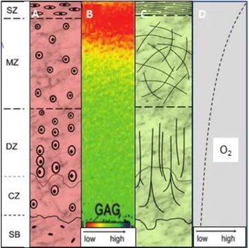
In articular cartilage four zones can be distinguished by differences in water and proteoglycans concentrations, gene expression, levels of oxygen, cell size, cell shape, metabolic activity, collagen fibril diameter and orientation (Figure I-1)[6, 18]. The first zone is the superficial that has two distinct layers: an acellular sheet of predominantly collagen fibres and a second layer composed of flattened chondrocytes. This zone plays important role for compressive strength of the tissue and possibly in isolation of cartilage from immune systems. The second zone is the middle or transitional that is composed of spherical chondrocytes randomly oriented on collagen. The third
Chapter I – General Introduction zone is the deep or radial zone that has the largest diameter collagen fibrils, the higher concentration of proteoglycans and the least concentration of water. The last zone (calcified) is a zone of mineralized tissue, hypertrophic and with circular chondrocytes. This zone lies closest to the subchondral bone and act as a transition from soft hyaline cartilage to bone [15, 19].
Figure I-1: Zonal organization in normal articular cartilage: superficial zone (SZ), middle zone (MZ), Deep zone (DZ), and Calcified zone (CZ) bellow which is the subchondral bone SB). Each zone is distinct in cell morphology (A), GAGs distribution (B), Collagen organization (C) and changes in oxygen levels (D)[ adapted from [6, 18]].
I-3. ARTICULAR CARTILAGE ASSOCIATED DISEASES
Traumatic injury and age-related degenerative diseases associated with cartilage are one of the most common health problems worldwide [20, 21]. Age-related diseases occur due to changes in the composition of ECM and organization of chondrocytes. With increasing of age there are changes in the zonal distribution of chondrocytes and as result the deeper layers have an increased number of cells when compared with the superficial layers. Other change is a decrease in the hydration of the matrix with a corresponding increase in compressive stiffness. The size of proteoglycans aggregates also decreases with the age [1].
The poor regeneration of adult articular cartilage is intrinsically associated with the limited number of chondrocytes, reduced repairs elements, absence of blood supply and innervations [22, 23]. In contrast to the adult cartilage, young cartilage has capacity to accelerate synthesis of ECM.
Chapter I – General Introduction
6
Spontaneous repair in adult cartilage usually results in primarily fibrous tissue at the superficial layers and fibrocartilage (mechanically and chemically inferior to hyaline cartilage). These repair tissues are unable to withstand the higher compressive loads during sports practice or even normal gaits and the predilection for the development of degeneration diseases (e.g. osteoarthritis) [14, 24, 25].
There are three main types of articular cartilage injury: matrix disruption, osteochondral or full thickness defects and chondral or partial thickness defects [26, 27]. Matrix disruption occurs from blunt trauma or age related matrix and it is responsible for ECM damaged. Full-thickness defects extend through the cartilage layer and penetrate the subchondral bone. As a result, the defects are filled within a fibrin clot. On the other hand, partial thickness defects do not penetrate the subchondral bone and immediately following the injury nearby cells begin to proliferate. This type of defect is not easily repaired as the full thickness defects because spontaneous repair is only achieved when the defects penetrates the subchondral bones, probably triggering a response from the mesenchymal stem cells (MSCs) presents in the marrow (Figure I-2) [14, 27, 28].
Figure I-2: Comparison between partial thickness defects and full thickness defects [28].
I-4. ARTICULAR CARTILAGE REPAIR THERAPIES
Millions of people require treatment to repair damaged cartilage due to limitation of its natural self-repair [29]. The therapies for articular cartilage defects can be divided into two major
Chapter I – General Introduction categories: conservative treatments and surgical procedures. The conservative treatments include physical therapies (e.g.: ice, supply of orthothesis) and/or drug administration. Nevertheless, these treatments only can modify and improve symptoms nevertheless none of these can heal cartilage defects. Conversely, the surgical procedures can reconstruct the surface of articular cartilage and there are several different types available. Surgical procedures include arthroscopy techniques (e.g.: bone marrow stimulating procedure, osteotomy, chondral shaving, debridement, lavage, abrasion arthoplasty, osteochondral drilling, microfracture, total joint arthoplasty, distraction of joints) and procedures that follow autogenic and allogenic tissue transplantation principles (osteochondral transplantation- mosaicplasty, perichondral / periosteal grafting) [2, 30, 31].
A wide range of clinical options emerged to repair focal lesions and damage to the articular cartilage. These approaches reduce the pain increase the immobility but present a limited extent and a short-term period. Thus, TE strategies are a significant clinical option in the treatment of damaged or diseased cartilage [13, 15, 32]. The principles of TE rely on the use of cells, biomaterials and microenvironmental factors, alone or in combination [33-35].
The advantages of TE approaches is the use of scaffolds that can provide the initial structure support and retain cells in the defective area which is follow degraded when the cells secrete their own ECM. General TE approaches for cartilage repair require some steps that are represented in Figure I-3. Briefly, cells are firstly isolated via biopsy from patient and then in order to obtain a large amount of cells bi-dimensional (2D) expansion is required. Due to the de-differentiation process and cartilage complex three-dimensional (3D) geometry isolated cells are reintroduced into a 3D environment, namely scaffold. Bioactive, biomechanical and chemical factors, as well as bioreactors, can be used to stimulate cartilage regeneration. Two basic methodologies are normally applied in cartilage TE approaches: ex vivo TE and in vivo TE. In ex vivo TE strategy the tissue is completely generated in vitro while in vivo TE strategies the construct is implanted with or without prior in vitro cultivation and allowed to mature in vivo [4, 36].
Chapter I – General Introduction
8
Figure I-3: General scheme representing cartilage TE approaches: in ex vivo TE and in vivo TE (adapted from [36]).
I-5. CELL SOURCE
The optimal source for cartilage TE approaches is still being identified. As a result, wide ranges of cells have been already tested such as chondrocytes, stem cells and genetically modified cells [4, 7, 37, 38]. Chondrocytes are the most obvious choice, because they are found in native cartilage and are responsible for secretion of the ECM. The sources normally used for cartilage repair are: auricular cartilage, articular cartilage, nasoseptal cartilage and costal cartilage. These cells, like the others, reside, proliferate and differentiate inside the body within a complex 3D environment. However, in contrast with other cell types, the isolated chondrocytes in 2D culture lose their differentiated phenotype [4, 5, 39]. The de-differentiation process is accompanied by morphological/cytoskeletal changes, different ECM synthesis and cell surface receptors profile (Figure I-4). The de-differentiation process can be limited when chondrocytes are cultured in a 3D environment [5, 38].
Chapter I – General Introduction
Figure I-4: Chondrocytes phenotype shift during dedifferentiation [adapted from table [38]].
MSCs are a promising strategy for articular cartilage due to their easy availability and multilineage differentiation capacity. These cells can differentiate into different cell types when stimulated by microenvironmental factors that are the driving motor for its differentiation [4, 5, 39-46]. The chondrogenic differentiation involves a 3D structure, growth and environmental factors. However, MSCs also have some limitations associated with in vitro expansion due to the potential loss of differentiation potential. Moreover, other potential obstacles exist, including cellular senescence and death, hypertrophy, and graft integration [44]. The most challenging problem in cartilage TE using MSCs is the terminal differentiation to hypertrophy, characterized by high levels expression of alkaline phosphatase and collagen type X [44].
I-6. MICROENVIRONMENTAL FACTORS
The microenvironmental factors are namely composed of mechanical and signalling molecules [47]. The signalling molecules should try to reproduce the natural sequence of signals guiding spontaneous tissue repair and cells. These molecules involved the use of bioactive molecules, generally represented by growth factors (GFs) and cytokines [48].
GFs are polypeptides secreted by a wide range of cells and play a role in either stimulating or inhibiting transmission of signals. The signals transmitted regulate cellular activities, such as migration, differentiation, proliferation and gene expression. These polypeptides elicit cellular action by binding to specific cellular receptors present on the surface of target cells that initiate a cascade of biological events to stimulate the regenerative process [48-52]. Cytokines are molecules secreted by immune cells to act on damaged or infected tissue. For cartilage regenerative process it has been shown that there are several essential GFs and cytokines that provide regulatory effects
Chapter I – General Introduction
10
on chondrocytes or stem cells involved in chondrocytes maturation and cartilage formation [50-57]. The GFs and cytokines for cartilage applications include: TGF-β superfamily, IGF, FGF, BMP, platelet derived growth factor (PDGF), epidermal growth factor (EGF), interleukins (ILs) and tumor necrosis factor (TNF-α) (Table I-1).
Table I-1: Regulatory effects of GFs and cytokines in articular cartilage
GFs and cytokines Function
TGF-β superfamily
Increase proteoglycans synthesis (TGF-β1); Prevent ECM degradation (TGF-β1); Induce inhibition of matrix metalloproteinase(MMP) (TGF-β1); Stimulate chondrogenic differentiation of progenitor cells (TGF-β1), chondrocyte proliferation (TGF-β1) and maturation (TGF-β3); Induce chemotaxis of inflammatory cells [36, 50, 58].
IGF - 1
Promote chondrocyte proliferation; Prevent apoptosis; Induce chondrogenic differentiation of progenitor cells; Stimulate chondrocyte proliferation; Prevent ECM degradation (inhibition of MMP) [36, 48, 59].
FGF
Promote chondrocyte proliferation; Stimulate deoxyribonucleic acid (DNA) and ribonucleic acids (RNA) synthesis; Promote ossification; Induce chemotaxis of inflammatory cells; Stimulate MMP and matrix degradation; Augment neovascularization [4, 36, 40, 51].
BMP
Stimulate prechondrogenic condensation and differentiation into chondrocytes (BMP-2, 4, 5, 6, 7); Induce the matrix synthesis (BMP-2, 4, 6, and 7) and sometimes degradation (BMP-2); Promote ossification (BMP-2) [4, 36, 40, 51].
PDGF Up-regulated the number of IL-1 per chondrocytes growth and differentiation of MSCs;
Stimulate MMP and ECM degradation; Promote ossification [4, 36, 40, 51].
EGF Induce chondrocytes proliferation; Induce matrix degradation [51].
ILs Induce MMP inhibition 4, 6) and stimulation 1 , 17, 18); Induce matrix degradation
(IL-1 , (IL-18) [4, 36, 40, 5(IL-1].
TNF- Stimulate MMP and matrix degradation [4, 36, 40, 51].
The mechanical factors applied to cartilage cultured in vitro may affect the synthesis and organization of components of articular cartilage. These factors stimuli cellular functions and may be transmitted to cells by forces affecting the cellular microenvironment. The mechanical factors normally applied are: oxygen tension and mechanical loading (deformation, hydrostatic pressure, fluid flow, shear stress and dynamic compression) [4, 5, 56].
Chapter I – General Introduction
I-6.1. Scaffold requirements for cartilage tissue engineering
Scaffolds provide the 3D environment that guides the differentiation and the development of the cartilaginous tissue. Such constructs should be designed with the adequate mechanical and physical-chemical characteristics, in order to mimic the native ECM structure and function [60-62]. As a result a number of requirements are necessary to be full filled and illustrated on Table I-2.
Table I-2: Scaffolds requirement for TE.
Scaffold Requirements Biological and material basis
Porosity Promote the integration of cells into the scaffolds which allow them to generate their
own ECM; Enhance implant fixation; Affect mechanical properties [60, 61, 63].
Pore size Affect cell infiltration, migration and distribution; Improve ECM deposition and
distribution [61, 64, 65].
Interconnectivity
Promotes cell migration throughout all the volume of the construct; Influence the diffusion of physiological nutrients and gases to cells and the removal of metabolic waste from cells [60, 61, 64].
Surface characteristics (topography, chemistry,
surface energy or wettability)
Affect protein adsorption and cell adhesion; Increase the interaction with the surrounding environment; Control cell migration, phenotype maintenance and intracellular signalling; Improve the recruitment of cells and the healing at the tissue-scaffold interface [66-69].
Biocompatibility Prevents inflammatory or immunologic reactions that comprise the host tissue;
Support cell adhesion and proliferation [60, 70].
Appropriate mechanical properties
Prevent leakage or extrusion after implantation; Support mechanical loading; Provide the correct stress environment for the neo-tissue [71].
Structural anisotropy Promotes native anisotropic tissue structure [60, 72].
Cell adhesiveness Improve cell seeding for delivery and retention of cells; Promote maintenance of
chondrogenic phenotype [60].
Bioactivity Act as delivery vehicles for biologics included: cells, genes, peptides and GFs [73].
Controlled degradation rate
Promote new tissue ingrowth and remodelling of the ECM; Match healing of new tissue assuring the initial strength of the scaffold [67, 74].
Geometry and architecture Support 3D tissue growth; Control the morphological of the growing tissue; Support
cell proliferation and differentiation [75].
Ideally, scaffold should fulfill, a serie of requirements (Table I-2) to promote matrix synthesis and optimal chondrocytes homing. The ability of scaffold to bond and integrate with native tissue is critical for obtain an homogeneous and functional repair [76].
Chapter I – General Introduction
12
Among the scaffolds requirements the porous network is a driving parameter in their design because is intimately connected to their mechanical properties (e.g: an increase in porosity results in a more flexible structure). The scaffolds should ideally mimic the mechanical properties of the native tissue. However this can result in a scaffold with low porosity and a decrease in nutreints diffusion, which can lead to possible necrosis. As a result, a balance between mechanical properties and porosity must be found. [67, 70, 76].
A wide range of scaffolds were already used, such as hydrogels, sponges, membranes, foams, fibrous meshes (microfiber and nanofiber-biomimetic the ECM, agglomerate particles, microspheres or composite of these materials [70, 77-83]. For all these scaffolds macro and micro-structural properties affect the cell survivor, signaling growth, propagation and reorganization [35, 65]. So far none currently available scaffolds fulfills all of the requirements and consequently a highly variable effects were already related in the growth, differentiation and maintenance of cells [36].
I-7. SCAFFOLD PROCESSING TECHNIQUES FOR CARTILAGE APPLICATIONS
Scaffolds are central element to TE strategies and a wide range of fabrication technologies have been developed to prepare them. Manufacturing processes should assure a high level of control over macro and micro-structural properties [84-86].
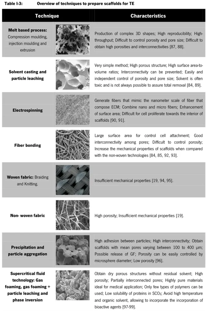
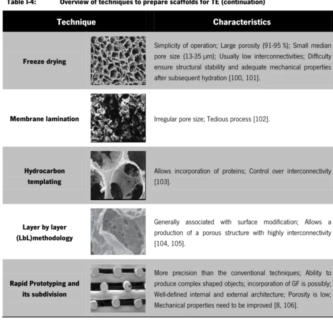
The different technologies used in scaffolds production dictates the type of structure and also affects some characteristics such as: mechanical properties, degradation behaviour, biocompatibility and surface properties [84-86]. The techniques normally used for scaffold production in TE approaches are presented in Table I-3 and Table I-4.
Chapter I – General Introduction
Table I-3: Overview of techniques to prepare scaffolds for TE
Technique Characteristics
Melt based process:
Compression moulding, injection moulding and
extrusion
Production of complex 3D shapes; High reproducibility; High-throughput; Difficult to control porosity and pore size; Difficult to obtain high porosities and interconnectivities [87, 88].
Solvent casting and particle leaching
Very simple method; High porous structure; High surface area-to-volume ratios; Interconnectivity can be prevented; Easily and independent control of porosity and pore size; Solvent is often toxic and is not always possible to assure total removal [84, 89].
Electrospinning
Generate fibers that mimic the nanometer scale of fiber that compose ECM; Combine nano and micro fibers; Enhancement of surface area; Difficult for cell proliferate towards the interior of scaffolds [90, 91].
Fiber bonding
Large surface area for control cell attachment; Good interconnectivity among pores; Difficult to control porosity; Increase the mechanical properties of scaffolds when compared with the non-woven technologies [84, 85, 92, 93].
Woven fabric: Braiding
and Knitting. Insufficient mechanical properties [19, 94, 95].
Non- woven fabric High porosity; Insufficient mechanical properties [19].
Precipitation and particle aggregation
High adhesion between particles; High interconnectivity; Obtain scaffolds with mean pores varying between 100 to 400 µm; Possible release of GF; Porosity can be easily controlled by microsphere diameter; Low porosity [96].
Supercritical fluid technology: Gas foaming, gas foaming +
particle leaching and phase inversion
Obtain dry porous structures without residual solvent; High porosity; Partially interconnected pores; Highly pure materials ideal for medical application; Only few types of polymers can be used; Low solubility of proteins in SCO2; Avoid high temperature and organic solvent, allowing to incorporate the incorporation of bioactive agents [97-99].
Chapter I – General Introduction
14
Table I-4: Overview of techniques to prepare scaffolds for TE (continuation)
Technique Characteristics
Freeze drying
Simplicity of operation; Large porosity (91-95 %); Small median pore size (13-35 µm); Usually low interconnectivities; Difficulty ensure structural stability and adequate mechanical properties after subsequent hydration [100, 101].
Membrane lamination Irregular pore size; Tedious process [102].
Hydrocarbon templating
Allows incorporation of proteins; Control over interconnectivity [103].
Layer by layer (LbL)methodology
Generally associated with surface modification; Allows a production of a porous structure with highly interconnectivity [104, 105].
Rapid Prototyping and its subdivision
More precision than the conventional techniques; Ability to produce complex shaped objects; incorporation of GF is possibly; Well-defined internal and external architecture; Porosity is low; Mechanical properties need to be improved [8, 106].
I-7.1. Layer-by-layer methodology
The design of a thin solid film at the molecular level has been first reported in 20 th century
and two techniques dominated this field: Langmuir-Blodget (LB) and self-assembled monolayers (SAMs). However, both present some drawbacks, which limited their application in biological field as represented in Figure I-5 [104].
Chapter I – General Introduction
Figure I-5: Schematic representation of drawbacks associated with LB and SAMs [adapted from [104, 107]].
A new technology called layer-by-layer, LbL, was developed by Decher and co-workers in 1992. LbL emerged as a simple technique to build films on a solid substrate with precise control of thickness and surface charge. As a result in comparison with LB technique, LbL is more simple and faster and result in more stable films while in comparison with SAM allows higher loadings of biological interesting species [104, 107-109].
LbL consists in alternately deposition of polyanions and polycations or bipolar amphiphlies that self-assembled and self-organize on the material surface leading to the formation of polyelectrolyte multilayer films (PEMs). The deposition of PEMs by LbL has emerged as promising technique because only requires a charged substrate and allows the functionalization of it. The substrate can range from planar to non-planar templates, such as colloids or microcapsules [110-114].
The driving forces of this process include electrostatic as well as non-electrostatic interactions, namely: hydrophobic interactions, van der Waals forces and charge transfer [115-117]. This technique is not only applicable for polyelectrolyte/ polyelectrolyte systems, but it can be expanded to almost any type of charged species, including inorganic molecules clusters, nanoparticles, nanotubes, nanowires, nanoplates, organic dyes, dendrimers, porphyrins, biological polyssacharides, polypeptides, RNA and DNA, proteins and viruses [104].
LbL have been applied in various areas including TE such as in biomimetic coatings, drug delivery, protein adsorption, bioactive coatings, biosensors and the coating of living cells [104, 117-124].
Thin solid films
LB
Expensive instrumentation; Long fabrication periods; Limited types of molecules
can be embedded.
SAMs
Low loading of biological components;
Limited number of substrates; Limited stability under physiological conditions;
Chapter I – General Introduction
16
I-7.1.1. Parameters
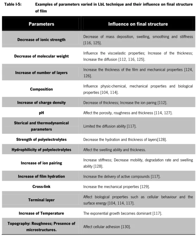
LbL methodology allow the production of tuned PEMs by varying several parameters, as represented in Table I-5 [114].
Table I-5: Examples of parameters varied in LbL technique and their influence on final structure of film
Parameters Influence on final structure
Decrease of ionic strength Decrease of mass deposition, swelling, smoothing and stiffness
[116, 125].
Decrease of molecular weight Influence the viscoelastic properties; Increase of the thickness;
Increase the diffusion [112, 116, 125].
Increase of number of layers Increase the thickness of the film and mechanical properties [124,
126].
Composition Influence physic-chemical, mechanical properties and biological
properties [104, 114].
Increase of charge density Decrease of thickness; Increase the ion paring [112].
pH Affect the porosity, roughness and thickness [114, 127].
Sterical and thermodynamical
parameters Limited the diffusion ability [117].
Strength of polyelectrolytes Decrease the hydration and thickness of layers[128].
Hydrophilicity of polyelectrolytes Affect the swelling ability and thickness.
Increase of ion pairing Increase stiffness; Decrease mobility, degradation rate and swelling
ability [128].
Increase of film hydration Increase the delivery of active compounds [117].
Cross-link Increase the mechanical properties [129].
Terminal layer Affect biological properties such as cellular behaviour and the
surface energy [104, 114, 117].
Increase of Temperature The exponential growth becomes dominant [117].
Topography: Roughness; Presence of
Chapter I – General Introduction LbL normally is used as a technique for surface modification, production of microcapsules and reservoirs for loading bioactive molecules. However, in 2011 Praveen et al. developed a technology for produced nanostructured 3D constructs combining LbL technology and 3D template leaching [105]. This thesis will mainly focus on such methodology in order to produce highly porous aimed to be used in cartilage TE.
I-8. POLYMERIC MATERIAL USED IN ARTICULAR CARTILAGE TISSUE ENGINEERING
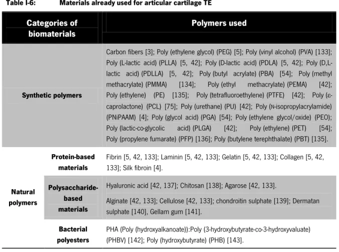
The selection of material for scaffolds still remains a fundamental key for the design and development of tissue engineering constructs. A wide variety of materials, both synthetic and natural, have been used in cartilage application taking account the need of avoiding any adverse foreign host response (Table I-6) [67, 131, 132]. As a result, the scaffold can be natural, synthetic or hybrid (natural and synthetic).
Table I-6: Materials already used for articular cartilage TE
Categories of biomaterials
Polymers used
Synthetic polymers
Carbon fibers [3]; Poly (ethylene glycol) (PEG) [5]; Poly (vinyl alcohol) (PVA) [133]; Poly (L-lactic acid) (PLLA) [5, 42]; Poly (D-lactic acid) (PDLA) [5, 42]; Poly (D,L-lactic acid) (PDLLA) [5, 42]; Poly (butyl acrylate) (PBA) [54]; Poly (methyl methacrylate) (PMMA) [134]; Poly (ethyl methacrylate) (PEMA) [42]; Poly (ethylene) (PE) [135]; Poly (tetrafluoroethylene) (PTFE) [42]; Poly (ε-caprolactone) (PCL) [75]; Poly (urethane) (PU) [42]; Poly (N-isopropylacrylamide) (PNiPAAM) [4]; Poly (glycol acid) (PGA) [54]; Poly (ethylene glycol/oxide) (PEO); Poly (lactic-co-glycolic acid) (PLGA) [42]; Poly (ethylene) (PET) [54]; Poly (propylene fumarate) (PFP) [136]; Poly (butylene terephthalate) (PBT) [135].
Natural polymers
Protein-based materials
Fibrin [5, 42, 133]; Laminin [5, 42, 133]; Gelatin [5, 42, 133]; Collagen [5, 42, 133]; Silk fibroin [4].
Polysaccharide-based materials
Hyaluronic acid [42, 137]; Chitosan [138]; Agarose [42, 133].
Alginate [42, 133]; Cellulose [42, 133]; chondroitin sulphate [139]; Dermatan sulphate [140], Gellam gum [141].
Bacterial polyesters
PHA (Poly (hydroxyalkanoate)):Poly (3-hydroxybutyrate-co-3-hydroxyvaluate) (PHBV) [142]; Poly (hydroxybutyrate) (PHB) [143].
Chapter I – General Introduction
18
I-8.1. Synthetic polymers
Synthetic polymers have been widely used for TE because they are more controllable and predictable than naturally derived polymers, whereas chemicals and physicals properties of the polymer can be tailored to match specific mechanical and degradation characteristics [4, 48]. Moreover, risks like toxicity, immunogenicity and infection are much lower for pure synthetic polymers. However, they have a lack of biological cues because these materials do not benefit from direct cell-scaffold interactions that could promote the desired cell response. In addition, some degradation products may be toxic or elicit an inflammatory response due to their accumulation and decrease of local pH derived of acidic products [48, 144].
I-8.2. Natural polymers
The growing interests in natural-based polymers relies on their economic and environmental aspects, as well as biocompatibility, biodegradability, low toxicity, low manufacture costs, low disposal costs and renewability [48, 145]. In addition, these polymers offer the advantage of being similar to biological macromolecules providing biological signalling, cell adhesion, cell responsive degradation and re-modelling [146-149]. Living organisms are able to synthesize natural polymers during the growth cycles. The synthesis is typically formed within cells by complexes metabolic processes, generally included enzyme-catalysed, chain growth polymerization reactions of activated monomers. Natural polymers can be divided into three major classes: polysaccharides, proteins and bacterials polyesters, such as PHAs (PHB and PHBV) [34, 145, 148].
Polysaccharides derive from virtually any renewable resources, namely wood, plants, animals and microorganisms. Biochemically, these materials consist of monosaccharides linked by O-glycosidic linkages [34, 145, 148]. They may be linear or branched, and may have single or mixed linkage between monosaccharides units. Differences between the monosaccharides, linkage types, chain shapes and molecular weight, dictate their physical properties, such as solubility, gelation capability and surface properties. The interest of polysaccharides as a material used for TE are related with non-toxicity, renewability, water solubility, stability to pH variations and their capacity to be chemical modified in order to achieve high swelling in water. However, they have low mechanical, thermal and chemical stability. They also cannot be processed alone using melt-base techniques and are usually shaped by solvent-based methodologies. Natural-based polymers may
Chapter I – General Introduction be combined with synthetic polymers to be processed using extrusion, injection moulding and compression moulding [34, 145, 146, 148, 150].
I-8.2.1. Chitosan
Among naturally derived polymers, chitin is one of the most abundant natural polymer that can be found in shells from crustaceous, cuticles insects and cell walls of fungi. The most important derivative of it is chitosan [151, 152]. Chitosan has been found as an excellent candidate in a broad spectrum of TE applications due to its characteristics, namely, biocompatibility, biodegradability, non-toxicity, remarkable affinity to proteins, along antitumoral, antibacterial, anticholesteremic, fungistatic and haemostatic properties [153-155]. This polysaccharide is obtained by a partial deacetylation of chitin under alkaline treatment (concentrated sodium hydroxide - NaOH) or by enzymatic hydrolysis in the presence of chitin deacetylase (Figure I-6) [138, 153, 155].
Figure I-6: Chemical structure of chitin and chitosan[adapted from [138].
Chitosan in solid state is a semicrystalline polymer with a high elastic modulus in the dry state owing to the high glass transition temperature [156, 157]. Structurally is a linear copolymer composed of glucosamine (deacetylated unit) and N -acetyl glucosamine (acetylated unit) units linked by β (1→ 4) glycosidc bonds and it is normally insoluble in aqueous solutions above pH=7. However, in dilute acids (pH below 6), the free amine groups are protonated and the molecule becomes soluble [158-160]. Generally, chitosan has three types of reactive functional groups, an amino group (C [2] position), a primary (C [3] position) and secondary (C [6] position) hydroxyl groups. These groups allow modifications, such as covalent ionic or graft copolymerization, which is very useful for TE applications [153, 155, 161].
The degree of deacetylation (DD) measures the ratio between glucosamine and N-acetyl glucosamine in polymeric chains. Depending on the source and preparation procedure, chitosan molecular weight may range from 300 to over 1000 kDa with a DD from 30 % to 95 % [155, 162].
Chapter I – General Introduction
20
The DD influences physicochemical properties, such as solubility, crystallinity, biodegradability, swelling behaviour and biological properties [155, 162, 163]. The degradation of chitosan in human body has been reported to be carried out by enzymatic hydrolysis with lysozyme. Lysozyme is a primary enzyme responsible for in vivo degradation of chitosan which appear to target acetylated residues [138, 164]. Studies have demonstrated that chitosan and its degraded products are involved in the synthesis of the articular components, including chondroitin sulphate, dermatan sulphate, hyaluronic acid, keratan sulphate, and type II collagen [165]. The degradation kinetic of this material appears to be inversely related to DD, as it occurs for crystallinity [47, 163, 164].
For articular cartilage TE the ideal cell-carrier substance should mimic the natural environment in the articular cartilage ECM [166]. Most of the potential of chitosan for this application is its structural similarity with cartilage-specific ECM components such as GAGs [47, 138]. Moreover, chitosan cationic nature and high charge density in solution allows electrostatic interactions with anionic species, such as GAGs and proteoglycans [47, 138, 156]. Consequently, numerous studies in vitro and in vivo have been demonstrated a positive influence of chitosan on chondrocyte behaviour. In vitro studies developed by Malafaya et al. showed that human adipose derived MSCs seeded onto chitosan particles agglomerated scaffolds had a capacity to differentiate the chondrogenic lineage [78]. In vivo performance of chitosan-glycerophosphate gels were evaluated by Chenite et al. by mixing them with primary culture bovine chondrocytes (bch) and implanting subcutaneously in athymic mice. The implant area revealed several areas of remodelling chondrocytes secreting a matrix characteristic of normal cartilage [167]. Lu et al. has also demonstrated that chitosan solution injected into the knee articular cavity of rats led to significant increase in chondrocytes density [168]. Mattioli-Belmonte et al. showed that BMP-7 associated with N-dicarboxylmethyl chitosan induces or facilities the repair of articular cartilage lesions in rabbits [169].
I-8.2.2. Chondroitin sulphate
Chondroitin sulphate is a linear, complex, sulphated unbranched polysaccharide belonging to the class of macromolecules known as GAGs [170-173]. It is composed of repeating dissacharide units of D-glucuronic acid and N-acetylgalactosamine linked by β-(13) bonds. Like other natural polysaccharides, chondroitin sulphate derives from animal sources by extraction and purification
Chapter I – General Introduction processes [170]. The animal sources generally used are chicken, porcine, bovine and cartilaginous fish such as sharks and skate [170, 174]. As a result chondroitin sulphate is a heterogeneous polysaccharide in terms of charge densities due to sulphate groups in varying amounts and linked in different positions, molecular masses, polydispersivity, chemical properties, biological and pharmacological activities [175, 176].
Figure I-7: Structures of disaccharides forming chondroitin sulphate. Different groups on R1, R2 and R3 give rise to different types of CS: R1=R2=R3=H non-sulphated chondroitin, R1=[ ]and R2=R3= H chondroitin-4-sulphate; R2=[ ]and R1=R3=H
chondroitin-6-sulphate; R2=R3=[ ]and R1=H chondroitin-2,6-disulphate; R1=R2=[ ]and
R3=H chondroitin-4,6-disulphate; R1=R3= =[ ] and R2=H
chondroitin-2,4-disulphate; R1=R2=R3==[ ] trisulphated chondroitin [175].
For cartilaginous tissues, this molecule (chondroitin-4-sulphate and chondroitin-6-sulphate) is an important structural component [177-180]. The tightly packed and highly charged sulphate groups of chondroitin sulphate generate electrostatic repulsion that provides much of the resistance of cartilage to compression and also cooperates in the shock absorbing capacity of aggrecans [47, 181]. Consequently, this polysaccharide with anionic nature enables efficient interaction with cationic molecules to form interesting structures [182, 183]. However, the major drawback of chondroitin sulphate is the high solubility in water, which limits its use alone in the solid state for biomedical applications, being frequently cross-linked or combined with other polymers, such as chitosan, hyaluronic acid, PVA, PLGA, PLLA, PCL, collagen, cellulose and gelatin [47, 177, 184-188]
Chondroitin sulphate is currently used as an ingredient in dietary supplements with the ultimate goal of relieving some of the pain and disability of patients with musculoskeletal pathologies, namely osteoarthritis [186, 189]. The benefits of chondroitin sulphate for the treatment of osteoarthritis are related with the stimulation of ECM production by chondrocytes, suppression of inflammatory mediators and inhibition of cartilage degeneration [190]. Thus, due to its nature, chondroitin sulphate has been used in the development of supports for cartilage TE
Chapter I – General Introduction
22
applications due to its chondroprotective ability and increased ECM synthesis [47, 191]. A number of recent studies have reported that chondroitin sulphate stimulates proliferation and matrix component production of seeded chondrocytes in collagen-GAG matrices in vitro [139, 192, 193]. Yan et al. reported in vitro and in vivo studies of a tri-copolymer matrix (collagen-chondroitin sulphate-chitosan). In vitro studies showed that chondrocytes adhered to the scaffold, where they proliferated and secreted ECM, filling the space within the scaffold. In vivo studies performed with subcutaneous implantation in nude mice demonstrated a homogeneous cartilaginous tissue similar to those of natural cartilage, when chondrocytes were seeded in collagen-chondroitin sulphate-chitosan matrix after implant of 12 weeks [194]. Collagen-GAG matrices were also used as a reservoir to GFs, namely IGF-I, and this combination demonstrate the increase of proteoglycan production in vitro.[195]. Fan et al. used PLGA–gelatin-chondroitin sulphate-hyaluronate hybrid scaffold and showed their capacity to induce differentiation of MSCs cells [196]. This material was also used in LbL methodology as polyanion and according to Gong et al. LbL assembly of chondroitin sulphate and collagen on aminolyzed PLLA porous scaffolds enhances their chondrogenesis [197].
I-8.2.3. Combination of chitosan and chondroitin sulphate
Several studies reported the combination between chitosan and chondroitin sulphate in various areas of TE, such as controlled release of drugs, conventional scaffolds, and surface modification with techniques like LbL methodology [47, 198-200]. Chitosan and chondroitin sulphate have analogous structures and this suggest that chitosan also can have specific interactions with GFs, receptors and adhesion proteins. However chitosan has poor mechanical strength limiting its application as biomaterial. Consequently combinations between this material and others became recurrent [191, 199, 201]. The combination with chondroitin sulphate occurs due to ionic interactions between the positively charged of chitosan and negatively charged of chondroitin sulphate. In 1976 this combination was called a film-like complex, due to their electrostatic interactions [202]. According to Denuziere et al. chitosan when associated with various polyelectrolytes has a protective effect against GAGs hydrolysis by their specific enzymes [191, 202].
For cartilage TE, the combination of chitosan with other materials, namely GAGs, reveals determinant due to the lack of other bioactive ECM components. The use of GAGs enhances the
![Figure I-2: Comparison between partial thickness defects and full thickness defects [28]](https://thumb-eu.123doks.com/thumbv2/123dok_br/17918103.850190/31.892.237.629.611.925/figure-i-comparison-partial-thickness-defects-thickness-defects.webp)
![Figure I-3: General scheme representing cartilage TE approaches: in ex vivo TE and in vivo TE (adapted from [36])](https://thumb-eu.123doks.com/thumbv2/123dok_br/17918103.850190/33.892.182.673.107.452/figure-general-scheme-representing-cartilage-approaches-vivo-adapted.webp)
![Figure I-4: Chondrocytes phenotype shift during dedifferentiation [adapted from table [38]]](https://thumb-eu.123doks.com/thumbv2/123dok_br/17918103.850190/34.892.243.675.101.336/figure-i-chondrocytes-phenotype-shift-dedifferentiation-adapted-table.webp)
![Figure I-5: Schematic representation of drawbacks associated with LB and SAMs [adapted from [104, 107]]](https://thumb-eu.123doks.com/thumbv2/123dok_br/17918103.850190/40.892.179.723.109.337/figure-schematic-representation-drawbacks-associated-lb-sams-adapted.webp)