Sérgio Miguel Rodrigues Fernandes
Bachelor of Science in Chemical and Biochemical Engineering
Spatially Controlled Surface Deposition of a
Versatile ATRP Macroinitiator by Inkjet Printing
Dissertation to obtain the master’s degree in Chemical and Biochemical Engineering
Advisor: Dr Joost Duvigneau, Visiting Assistant
Professor, University of Twente.
Co-advisor: M. Sc.Marco Cirelli, PhD student,
University of Twente.
Jury:
President: Prof. Mário Eusébio Questioner(s): Dra. Teresa Casemiro
Vowel(s): Prof.a Dra. Maria Miranda Reis
II
III
Sérgio Miguel Rodrigues Fernandes
Bachelor of Science in Chemical and Biochemical Engineering
Spatially Controlled Surface Deposition of a
Versatile ATRP Macroinitiator by Inkjet Printing
Dissertation to obtain the master’s degree in Chemical and Biochemical Engineering
Advisor: Dr Joost Duvigneau, Visiting Assistant
Professor, University of Twente.
Co-advisor: M. Sc.Marco Cirelli, PhD student,
University of Twente.
Jury:
President: Prof. Mário Eusébio Questioner(s): Dra. Teresa Casemiro
Vowel(s): Prof.a Dra. Maria Miranda Reis
IV
V
Copyright
Spatially Controlled Surface Deposition of a Versatile ATRP Macroinitiator by Inkjet Printing
Copyright © 2018 –Sérgio Miguel Rodrigues Fernandes and Faculty of Science and Technology
– New University of Lisbon.
All rights reserved
The Faculty of Science and Technology has the right, perpetually and without geographical limits,
to file and publish this dissertation thought printed copies reproduced in paper or in digital format,
or any other means known or to be invented, and to disseminate it through scientific repositories
and to allow them to be copied and distributed for non-commercial educational or research
VI
VII
Acknowledgements
First and for most, I would like to thank the MTP group for allowing me to do the
dissertation within the group, in particular, G. Julius Vancso who is a person that I hold the utmost
respect and admiration and also Joost Duvigneau that reminded me of a strong-willed that has
clear purposes in mind as all good supervisors should have. Being my daily supervisor, I would
like to thank Marco Cirelli, which inspired me with his long and intense working habits without
never holding his smile throughout the day. I will always remember the traditional 10h30pm
meetings and the memorable expressions such as “I will be right back, 30s” or the “tché” everytime I needed further explanation but more importantly, the “work hard, play hard” motto that sums pretty well the work hard but enjoy life personality that you have. I also wanted to thank
everyone that was part of the MTP family during my time there for all the support and for the way
you made me feel like a true member of the family. Particularly, I want to thank Clemens for all
the help that he gave me and for showing me how I will be in the future, and Paola, my Erasmus
“mom”, that was always there for me from day one to my final day. I won't forget the songs that we sang, our dinners, the late nights at the lab, the pool games or even the day I broke my and
you went to buy one super early in the morning.
I want to thank my parents for always being there for me all these years and for allowing
me to fulfil every experience that I craved to do during my university journey. I'm grateful that
you were the rock I needed to hold to now fly for other experiences. To the rest of my family,
thank you as well for accompanying me in this journey, and for all the words of encouragement
when I was abroad.
Thank you as well to the many friends that I made throughout my journey as a university
student and that without them this path would have lost its heart and its essence. Of those many
friends, Kets and Catarina deserve a special mention for visiting me during my time in Twente
and Gonçalo for the frequent conversations that we had as we both participated in the Erasmus
program.
Last but not least, to all my friends outside the university and my friends from Nave de
Haver that were with me all these years and that supported me in this final chapter of this last five
amazing years. From family and friends that I made in the pass to the new connections that I made
VIII
IX
Resumo
Funcionalização de superfícies de ouro para possíveis aplicações em revestimentos com
uma técnica de deposição bem definida de um passo, nomeadamente, impressora de jato de tinta,
foi alcançado de acordo com a seguinte metodologia:
Primeiramente, o macroiniciador de polimerização radical de transferência de átomos, i.e
poli[metacrilato de 2-(2-bromoisobutiriloxy) etilo] (PBIEM) foi sintetizado através de
transferência de fragmentação de adição reversível (RAFT) do metacrilato de 2-hidroxietil
(HEMA) e a sua subsequente funcionalização com brometo de α-bromoisobutirilo (BIBB), ver
esquema 5-1 e esquema 5-2. Espectroscopia de infravermelho por transformada de Fourier com
reflectancia total atenuada (ATR FT-IR) e espectroscopia de ressonância magnética nuclear de
protões (1H-NMR) confirmaram a sucesso síntese de poli(HEMA), PHEMA, por RAFT, ver
figura 5-2. A partir de 1H-NMR, o peso molecular por número (M
n) de um precursor preparado
foi determinado como sendo aproximadamente 23 kDa (6th PHEMA). Esta funcionalização de
PHEMA com BIBB foi também confirmado por ATR FT-IR e 1H-NMR, ver figura 5-4 e figura
5-5.
Segundo, o PBIEM preparado foi depositado numa superfície de ouro através de
impressão de jato de tinta. Diversas tintas foram produzidas sendo que a PBIEM-B (derivada da
6th PHEMA) 10% (p/p) em N, N-dimetilformamida (DMF) rendeu camadas de enxerto mais
densas. Medições de angulo de contacto de água (CA) e microscopia de infravermelho foram
usadas para provar o enxerto do macroiniciador de ATRP em ouro. As imagens de altura do passo
da microscopia de forca atómica (AFM) forneceram a espessura e rugosidade de camadas
iniciadoras em superfícies de ouro. A espessura da camada de PBIEM obtida e de
aproximadamente ~17 nm.
Por fim, as cadeias laterais constituídas por poli(N-isopropilacrilamida) (PNIPAM) foram
sintetizadas via “grafting from” por ATRP para produzir estruturas do tipo escova de garrafa. Microscopia de infravermelho e AFM foram utilizadas para confirmar a fabricação bem-sucedida
de polímeros escova de garrafa. Conversões ate 15% foram obtidos.
Palavras chave: Impressora de jato de tinta, polimerização RAFT, ATRP, escova de
X
XI
Abstract
Functionalization of gold surfaces for possible coating applications with a one-step
pattern deposition technique in inkjet printing was achieved by the following methodology:
First, the atom transfer radical polymerization (ATRP) macroinitiator, i.e.
poly[2-(2-bromoisobutyryloxy) ethyl methacrylate] (PBIEM) was synthesised by the reversible-addition
fragmentation transfer (RAFT) polymerization of 2-hydroxyethyl methacrylate (HEMA) and its
subsequent functionalization with α-bromoisobutyryl bromide (BIBB), see scheme 5-1 and 5-2. Attenuated total reflectance Fourier transform infrared spectroscopy (ATR FT-IR) and proton
nuclear magnetic resonance spectroscopy (1H-NMR) confirmed the successful synthesis of
poly(HEMA) (PHEMA) by RAFT, see figure 5-2. From 1H NMR spectra, the number-average
molecular weight (Mn) of one prepared precursor was determined to be approximately 23 kDa (6th
PHEMA). The functionalization of PHEMA with BIBB was confirmed by ATR FT-IR and 1
H-NMR spectroscopy as well, see figure 5-4 and figure 5-5.
Secondly, the prepared PBIEM was deposited on gold surface by inkjet printing. Several
inks were produced being that the PBIEM (derived from 6th PHEMA 23kDa) 10% (w/w) solution
in N, N-Dimethylformamide (DMF) yielded more dense grafting layers. Water contact angle
measurements (CA), optical microscopy and infrared microscopy were used to prove the grafting
of the ATRP-macroinitiator on gold. The atomic force microscopy (AFM) step height images
provided the thickness and roughness and of deposit initiator layers on gold surfaces. The obtained
PBIEM layer thickness is approximately ~17 nm.
Last, poly(N-isopropylacrylamide) (PNIPAM) side chains were synthesised via grafting
from by ATRP to produce bottlebrush type structures. Infrared microscopy and AFM were used
to confirm the successful fabrication of bottlebrush polymers. Conversions up to 15% were
obtained.
Keywords: Inkjet printing, ATRP macroinitiator, RAFT polymerization, ATRP,
XII
XIII
Table of Contents
... 1
1.1 Introduction ... 1
1.2 Theoretical introduction ... 2
1.2.1 Controlled Radical Polymerization (CRP) ... 2
1.2.2 RAFT polymerization ... 4
1.2.3 ATR polymerization ... 6
1.2.4 Inkjet Printing ... 7
State of Art ... 9
2.1 ATRP Macroinitiator ... 9
Bottlebrush polymer synthesis ... 10
Exemplar though-out applications ... 12
2.3.1 Antifouling surfaces ... 12
2.3.2 Stimuli-responsive surfaces... 12
Intruments Theory ... 13
3.1 NMR ... 13
3.2 ATR FT-IR and ATR FT-IR microscopy ... 15
3.3 AFM ... 17
Experimental methods ... 19
4.1 Materials ... 19
4.2 Molecular Characterization ... 20
4.3 Equipment configuration ... 20
4.3.1 Rheometer ... 20
4.3.2 Inkjet Printing ... 20
4.3.3 Spin coating ... 21
4.3.4 CA ... 21
4.3.5 AFM ... 21
4.4 Fabrication method ... 21
4.4.1 RAFT Polymerization of HEMA ... 21
4.4.2 Preparation of PBIEM ... 22
Results and discussion... 23
5.1 RAFT Polymerization of HEMA ... 23
5.2 Preparation of PBIEM ... 26
5.3 Inkjet Printing ... 29
Bottlebrush application ... 37
6.1 Introduction ... 37
6.2 Preparation of bottlebrush ... 38
6.3 Results and discussion ... 39
Conclusion and recommendation ... 43
References ... 45
XIV
XV
Table of Figures
Figure 1-1 Comparison between RAFT, ATRP and NMP in the areas related to the synthesis of low molecular weight (LMW), end functional polymers (End Funct), block copolymers (Blocks), range of polymerizable monomers (Mon Range), synthesis of various hybrid materials (Hybrids), environmental issues (Env) and polymerization in aqueous
media (Water)………3
Figure 1-2 SciFinder results on the legend topics………..………..4
Figure 1-3 Schematic representation of continuous (A) and drop-on-demand inkjet printing (B)………..7
Figure 1-4 Representation of DOD inkjet printing mechanisms: Thermal (left side) and piezoelectric (right side)…….8
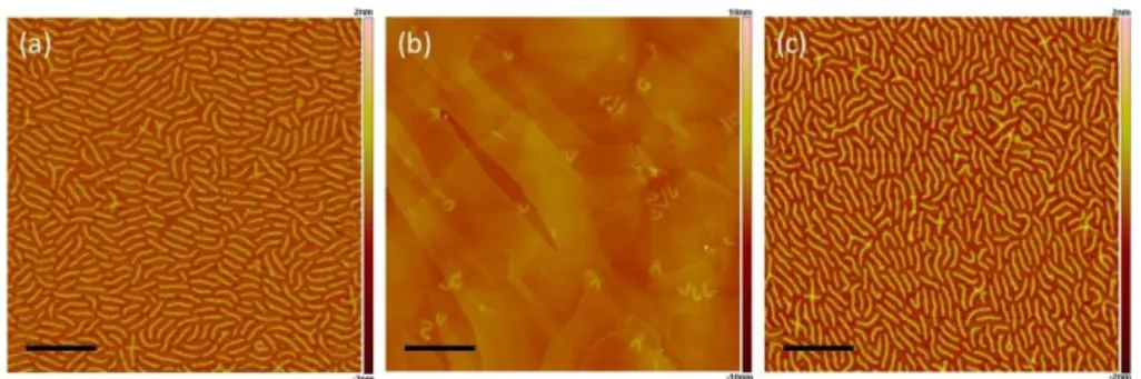
Figure 2-1 AFM images of molecular bottlebrushes as presented in the article: (a) PBIEM-g-P(nBA), (b) PBIEM-g-PSt, and (c) PBIEM-g-PDEGA. All scale bars have 400 nm length……….11
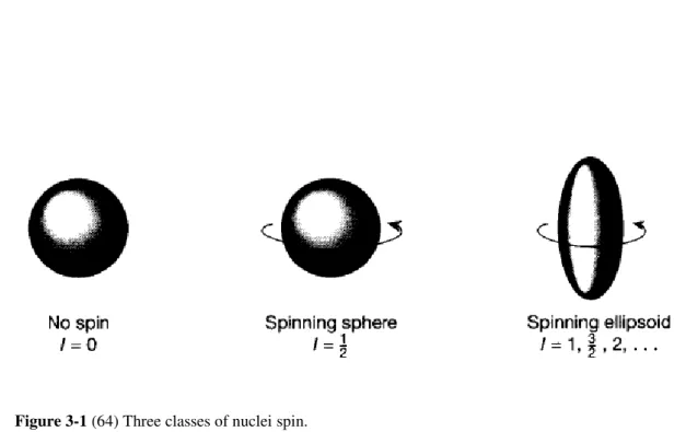
Figure 3-1Three classes of nuclei spin………....…….……….……….13
Figure 3-2 Precessional range of motion for a spin 1 2 nuclei under a magnetic field…………...14
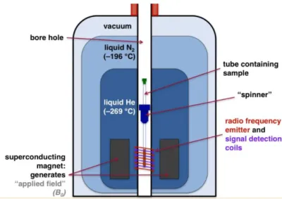
Figure 3-3Representation of the inside of an NMR machine………..………14
Figure 3-4 Potential energy of a diatomic molecule as a function of the atom’s separation with quantized vibration quantum numbers displayed………15
Figure 3-5ATR module work principle………...16
Figure 3-6 Schematic representation of AFM procedure………17
Figure 3-7AFM tapping mode mechanism………18
Figure 5-1RAFT polymerization linear kinetic plots of HEMA………24
Figure 5-2 NMR spectra of CPAD (a), HEMA (b), PHEMA (c)……….25
Figure 5-3 ATR FT-IR spectra of 6thPHEMA with highlighted characteristic peaks……….26
Figure 5-4 NMR of a) PBIEM-A, and b) HEMA in CDCl3. Two dashed lines exhibit the shift of the methylene protons after BIBB coupling………28
Figure 5-5 ATR FT-IR of a) PBIEM-A and b) PHEMA. Typical PBIEM peak is showcased in 2)………...28
Figure 5-6 Graphic representation of some viscosity percentual increase combinations: PBIEM-A 0.5% in DMF (blue line) and in acetone (red line) (bottom figure), PBIEM-A DMF 10% (blue line) and 0.5 % (red line) (centre figure), 10% DMF PBIEM-B (blue line) and PBIEM-A (red line) (top figure)………..………...31
Figure 5-7 Drop formation of PBIEM-A 10% in DMF (a), and PBIEM-A 0.5% in acetone (b)………..32
Figure 5-8 PBIEM-A 0.5% in acetone (left side) PBIEM-A 10% in DMF (right side)………...32
Figure 5-9 Pattern arrays of PBIEM-A 0.5% in acetone (left side) and PBIEM-A 10% in DMF (right side)……….………...……….33 Figure 5-10 Optical microscope images of PBIEM-B 10% in DMFdeposit ink droplets before (left side) and after washing (right side). On the left, a typical dewetting of the ink and the right visible scratches caused during the handling and the washing of the samples is shown……….33
Figure 5-11 Patterned ink drops constituted of PBIEM-B 10% in DMF………..………...34
Figure 5-12 ATR FT-IR microscope spectra of PBIEM-B 10% in DMF and the molecular mapping imaging. Each dot colours gives a different spectrum with the same colour………..………....35
XVI
XVII
Table of Tables
Table 5-1Characterization of PHEMA produced………...24
Table 5-2PBIEMs synthesised from PHEMA………..………27
Table 5-3Different ink characterization and ATRP macroinitiator layer height………..30
Table 5-4Variable denomination for the ATRP macroinitiator, solvent and composition………...30
Table 5-5Viscosity percentual increase dependency………….………...30
XVIII
XIX
Table of Schemes
Scheme 1-1RAFT polymerization mechanism………..…..5
Scheme 1-2ATR polymerization overall mechanism………...7
Scheme 5-1 RAFT polymerization of HEMA using CPAD as CTA agent……….………...…..23
Scheme 5-2Esterification reaction of PHEMA with BIBB………..……….…………..……27
.Scheme 5-3Defined deposition of ATRP macroinitiator ink by inkjet printing………..……..…….29
Scheme 6-1 Inkjet printing of ATRP macroinitiator (left side) with subsequent bottlebrush synthesis via grafting
from……….38
XX
XXI
Symbols and Abbreviations
µ magnetic momentum
ν vibration energy level
η refractive index
ϴ angle
µCP microcontact printing
1H-NMR Proton nuclear magnetic Resonance
AFM atomic force microscopy
AIBN 2,2’-azobis-2-methylpropionitrile
ATR FT-IR Attenuated total reflectance Fourier transform infrared spectroscopy
ATRP atom transfer radical polymerization
nBA butyl acrylate
BIBB α-bromoisobutyryl bromide
iBnA isobornyl acrylate
CDCl3 chloroform-d
CPAD 4 cyano-4-(phenyl-carbonothioylthio) pentanoic acid
CRP controlled radical polymerization
CTA chain transfer agent
DEE diethyl ether
DMF N, N-Dimethylformamide
DMSO-d6 dimethyl sulfoxide
DOD drop-on-demand
DPn degree of polymerization
Fbg Fibrinogen
FRP free radical polymerization
HEMA 2-hydroxyethyl methacrylate
HEMA-TMS 2-(trimethylsilyloxy)ethyl methacrylate
Mn molecular weight by number
MMA methyl methacrylate
Mw molecular weight by weight
NIPAM N-isopropylacrylamide
NMP nitroxide-mediated polymerization
XXII
PBIEM poly[2-(2-bromoisobutyryloxy) ethyl methacrylate]
PDEGA poly[(di-ethylene glycol)ethyl ether acrylate]
PDI polydispersity index
PGMA poly(glycidyl methacrylate)
PHEMA poly(2-hydroxyethyl methacrylate)
pLED polymeric light-emitting diode
P(nBA) poly(n-butyl acrylate)
PMDETA N,N,N’,N’’,N’’-Pentamethyldiethylenetriamine
PMEO2MA poly(2-(2-methoxyehtoxy) ethyl methacrylate)
PMMA poly(methyl methacrylate)
PRE persistant radical effect
PSt poly(styrene)
RAFT reversible-addition fragmentation transfer
THF tetrahydrofruran
1
1.1
Introduction
Inkjet printing of polymer-based inks is an attractive non-contact patterning technique
used for many applications due to its ability to precisely deposit small droplets of ink in
well-defined patterns on various substrates providing enhanced surface properties, e.g., multicolour
polymeric light-emitting diode (pLED) displays and polymer electronics.(1, 2) In this project, we
aim to functionalize gold surfaces with polymer brush patterns by i) grafting an ATRP
macroinitiator with inkjet printing and ii) the subsequent growth of polymer brushes in the
nanometre scale to be used in coating applications. Our approach will allow us to combine surface
templating techniques and polymer brush synthesis to obtain surface properties on demand using
a versatile fabrication technique to design patterned polymer brushes on the nanometre scale,
bypassing the use of masters and stamps as in other common patterning techniques such as
photolithography and microcontact printing (µCP).(3)
ATRP macroinitiators represent the future of coating technology as they enable the
formation of complex architectural structures in bottlebrush type polymers films (molecules that
are a subcategory of polymer brushes) that are very interesting since they may exhibit similar
surface properties characteristic of polymer brush films, as said by Li et al. that reported the first
study on surface properties of bottlebrush polymer thin films.(4) These films are currently used
in the preparation of antifouling surfaces,(5-7) stimuli-responsive surfaces,(8, 9) By using
bottlebrush polymers instead of brush polymers, higher grafting density surfaces can be achieved
and also a higher efficiency towards a targeted application of choice due to specific homo or
copolymer side chain configuration. Controlled radical polymerization techniques are critical in
designing well-defined macromolecules as they provide control over molecular weight and
dispersity. Of all these techniques, RAFT polymerization was chosen for the preparation of ATRP
2 typically dithioester, which is a direct pathway, to the assembly or immobilization of graft layers
onto gold surfaces.(10)
For templating techniques, both photolithography(11) and µCP(12) (also known as soft
lithography) have been used to pattern surfaces however, inkjet printing potential is immense
even for areas that this technique has not been used before as described by Berend-Jan de Gans
and Ulrich S. Schubert.(13) Inkjet printing is very attracting technique because it’s completely digital thus changing the printing design has little further cost impact.(14) Other advantages of
inkjet printing include tunability of the ink formulation, the overall flexibility of the technology,
easy reproducibility (possibility of automatization) and the possibility of depositing very small
amounts of material.(1)
1.2
Theoretical introduction
1.2.1
Controlled Radical Polymerization (CRP)
Due to its simplicity, free radical polymerization (FRP) has been widely adopted in many
industrial and laboratory scale polymerization processes since its maturity in the 1950s and
1960s.(15) In the last four decades, however, research efforts have been shifted to unveil new
techniques that allowed the production of macromolecules with controlled structures not
achievable in FRP mechanisms. It was with the discovery of living anionic polymerization by
Michael Szwarc in 1956 that made the pathway for major developments in other polymer
synthetic areas that allow the production of well-defined polymers with precise molecular
architectures.(16) The new techniques based on CRP, because of its inherent radical
intermediaries they possess similar limitations as in FRP, namely chemo-, regio-, stereo-
selectivities and unavoidable radical termination.(16) However, in contrast to FRP, where all
chains terminate, only a fraction of active chains between 1 and 10% terminate in CRP. The
remaining dormant chains are capable of reactivation, functionalization and chain extension to
form other structures such as block copolymers.(17) As it’s the case in designing complex structures to produce macromolecules with defined molecular weight and very narrow
polydispersity it is critical that all chains grow simultaneously via nearly instantaneous initiation
and that chain termination reactions are minimized. This concept derives from living
polymerization that by definition is a chain growth process without chain breaking reactions such
as transfer or termination.(18, 19) Polymerizations that combines fast initiation and an absence of
termination reactions have the potential to obtain well defined macromolecular structures. So
3 the inherent nature of radical reactions, particularly coupling or disproportion, it’s impossible to have a polymerization reaction completely absence of termination reactions and so it is only
possible to develop polymerization conditions that exhibit living characteristics.
There are three main mechanisms that have been used to achieve controlled radical
polymerization. The first mechanism is the reversible recombination of growing radicals with
scavenging radicals namely nitroxide-mediated polymerization (NMP) first described by
Solomon and Rizzardo.(20) (21) The first example of this mechanism is the thermal
polymerization of controlled styrene chains with a stable free radical TEMPO as described by
Georges et al. in 1993.(22) Currently the scope of NMP has greatly expanded over the years with
better control of a wide variety of monomers.(23) The second mechanism is the reversible
termination of growing radicals as it is found in ATRP that are trapped in transition metal
complexes. Metal such Li(24), Mo(25), Re(26), Fe(27, 28), Ru(29), Ni(30) and Cu(31) are proven
to successfully mediate ATRP reactions.(16) The third mechanism is based on a degenerative
exchanging process involving reversible chain transfer as in RAFT. High molecular conversions
(≈95%) of methyl methacrylate and butyl methacrylate have been reported.(32) Comparison between this three techniques from a target structure is given (figure 1-1) where the left side
indicates the state of the techniques in 2002 and the right side indicates the latest comparison in
2006, as described by Matyjaszewski.(16, 33) It is also important to notice that, in concordance
with the major developments shown in figure 1-1 regarding the ATRP capacity to control
macromolecular architecture, perhaps due to not only the inherent mechanisms characteristic of
this technique but also the numerous derivations processes from ATRP that have been created
that greatly expanded the current possible applications, the cumulative number of publications
Figure 1-1 (16,33) Comparation between RAFT, ATRP and NMP in the areas related to the synthesis of
low molecular weight (LMW), end functional polymers (End Funct), block copolymers (Blocks), range of
polymerizable monomers (Mon Range), synthesis of various hybrid materials (Hybrids), environmental
4 regarding this technique also increased far over the other CRP techniques (figure 1-2) being the
possible main reason the many commercially available reagents synthesised under undemanding
reaction conditions.(34)
1.2.2
RAFT polymerization
RAFT polymerization, as a CRP technique, it has the ability to allow the fabrication of
predetermined structures such as amphiphilic block copolymer chains, star polymers and other
complex architectures, end functional polymers and self-assembly and/or stimuli-responsive
polymers.(15) The most common mechanism for RAFT polymerization is shown in scheme 1.1.
Initiation occurs as in conventional radical polymerization: for example, thermal decomposition
of radical initiators is more widely used than other reported sources such as thermal autoinitiation
of monomers, photochemical reaction of the chain transfer agent, CTA, by ultraviolet light,
gamma radiation and pulsed laser irradiation(36). In step 1 of the initiation process, polymeric
radicals are formed (Pn•) upon monomer addition to the initiator species. The propagating radicals
produced in this step react with the chain transfer agent, CTA, (1) in step 2 of initialization. The radical intermediate (2) fragments reverting to its original composition or forms a polymeric structure named macro-RAFT agent (3) and a new radical (R•). The propagation step sees those radicals (R•) reacting with monomer units further growing the polymer chains (Pm•). The new
propagation radical rapidly reaches a chain equilibrium between the active propagating radical
and the dormant polymeric macro-RAFT agent complex.(37) The rapid degenerative exchange
(kaddP) that originates the stabilized radical intermediate (4), ensures the equal probability for all
chains to grow with roughly the same dispersity since rapid exchange sees the concentration of
5 radicals be kept lower than (4) and thus limiting termination reactions.(36) Termination events, like the initiation step, also occur in concordance with FRP meaning this termination processes
can occur via combination or disproportionation mechanism.(36)
Since systems that are ruled by degenerative transfer follow typical FRP kinetics to be
able to obtain macromolecules with a narrow polydispersity index (PDI), the appropriate choice
of CTA must carefully be made. The Z and R groups (1) play a critical part in this selection as the first one determines the reactivity towards propagating radical and the stability of the
intermediate radicals (2 or 4, respectively) and the last one, being the homolytic leaving group, it determines the leaving group ability and the reinitiation efficiency of R•that should be ≥kp.(37)
Quantitatively speaking the properties of RAFT agents can be determined by two transfer
coefficients, Ctr (=ktr/kp) and C-tr (=k-tr/ki) where ktr and k-tr are the rate constants for chain transfer,
kp and ki are the rate constant for propagation and initiation, respectfully. The linear dependence
of molecular weight on conversion and low dispersity (PDI< 1.2) typical of living polymerizations
require a Ctr of at least 10, however more effective RAFT agents have Ctr > 100.(38)
6
1.2.3
ATR polymerization
ATRP was reported for the first time independently in 1995 by Mitsuo Sawamoto,(39)
Krzysztof Matyjaszewski and Jin-Shan Wang.(40) This mechanism relies on the persistent radical
effect (PRE).(41, 42) The PRE is a kinetic feature which promotes a self-regulation effect in all
CRP systems that obey this parameter. Propagating radicals (Pn*) are trapped in a deactivation
process (kdeact) with persistent radicals (Mtn+1/L), scheme 1-2. Those radicals cannot terminate
with each other, unlike the propagating radicals, but only cross-couple with the growing radicals.
Thus, with time the concentration of radicals as well as the probability of termination reactions
decrease due to the irreversible accumulation of persistent radicals caused by radical-radical
termination and so growing radicals are predominantly reacting with chemical species.(16) The
dormant species, which exists in the form of alkyl halides, for example, a macromolecular species
(Pn-X), periodically reacts with an activator as in the transition metal complex (kact) in their lower
oxidation state, Mtn/L (Mtn represents the transition metal species with an oxidation state of n and
L is the ligand), forming the growing radicals that can propagate with the vinyl monomer (kp) and
a deactivator in the form of a transition metal species with a higher oxidation state, as a result of
halide connection, X-Mtn+1/L.(34) The propagating radicals formed can also terminate as in FRP
or be reversibly deactivated to the dormant chain state. To obtain polymeric chains with low
polydispersity values is necessary to have high monomer conversions (p), high degree of
polymerization by number (DPn), a high concentration of the polymer chain in a dormant state
(Pn-X) and small ratios of kp/kdeact (equation 1-1). According to the equation 1-1, note that low
concentrations of catalysts can be used and still provide control over the polydispersity if they
have sufficiently high values of kdeact, however, the amount of transition metal cannot indefinitely
decrease as it requires a sufficient concentration of deactivator.(16)
Equation 1-1 PDI equation for ATRP reactions.
Moreover, the key for a successful reaction, the ATRP equilibrium (KATRP=kact/kdeact)
must be strongly favoured towards the dormant species meaning rate constant of deactivation
must be substantially bigger than the rate constant of activation. Factors such the structure of the
ligand, monomer/dormant species compatibility and reaction conditions (e.g. temperature,
pressure, solvent) can significantly influence the values of the rate constants, kact and kdeact and
thus, kATRP.
PDI =MMw
n = 1 +
1
DPn+ (
kp[Pn− X]
7
1.2.4
Inkjet Printing
In order to functionalize surfaces, the appropriate deposition technique has to take into
account the targeted final application. Solvent-based techniques, such as spin-coating, dip-coating
and inkjet printing can be used to prepare bottlebrush thin film layers however this last type of
modifying surfaces have not been reported until Li et al. study.(4) Inkjet printing is a complex
technique capable to deposit a variety of inks with different properties and thus requires the
appropriate care for successful printing deposition.
There are two modes to deposit polymers based inks: continuous or drop-on-demand
(DOD) (Figure 1-3). In continuous mode, the ink is pumped through a nozzle forming a
continuous stream of sized droplets. The generated droplets are selectively charged via signals
from the printer by being subjected to an electrostatic field. The charged drops are then deflected
in a deflection field, which determines where the drop lands.(44) Depending on the system used,
the charged droplets can be printed onto the matrix or collected into a recirculation system to be
later reused. Continuous mode can print at high speeds, the nozzle is not easily clogged and has
the ability to use inks based on volatile solvents allowing rapid drying adhesion. Disadvantages
to this mode include low print resolution, the use of inks that are capable of being charged, high
investment cost as the printer has a drop selection section and a recycling unit followed by high
maintenance costs.(45) On drop-on-demand mode, a pressure pulse is created to eject ink droplets
Scheme 1-2 (43) ATR polymerization overall mechanism.
8 through a nozzle. DOD inkjet printers main deposition technologies are either thermally or
piezoelectrically.(46) Thermal inkjet printers (Figure 1-4 left side) rely on rapidly heating up the
ink present in the ink chamber, with the use of a resistor, to temperatures high enough to vaporize
the ink. This instantly pushes the ink droplet out through the nozzle until all the heat stored in the
ink is used, then the bubble collapses and refills the chamber.(47) Piezoelectric inkjet printers
(figure 1-4 right side) materials deform when submitted to an electric impulse and it’s through this mechanism that the ink is ejected out of the nozzle. Additionally, because this types of printers
are not regulated by heating processes they accept a wider range of inks and they possess print
heads that last longer in comparison with thermal print heads.(45)
There are currently four main types of inks used: phase-change, solvent-based,
water-based and UV curable.(44) Within the direction of this work, the inks formulated insert themselves
in the solvent-based inks, more precisely additives. A major factor for successful printing relies
on the ink rheological properties, particularly the viscosity and the surface tension. The viscosity
should be low, typically below 20 cP, as higher values have the potential danger of viscously
dissipating too much kinetic energy preventing droplet ejection.(1) The spheroidal shape of the
liquid drop is controlled by the surface tension and its behaviour can be theoretically predicted
with a physical constant named Weber number, with fluids with high Weber values, are more
likely to present non-spheroidal shapes. Considering all the factors for successful printing
mentioned above, a commonly used parameter to indicate the capacity for good printability is the
Z parameter [the inverse of the Ohnesorge number (Oh)], where values between 1 and 10 are
expected to generate stable drop formation.(45)
Besides the rheology properties of the ink, to ensure define printability, ink formulation
must also be compatible with wettability to ensure that the ink and the substrate reach a phase of
equilibrium between themselves and the environment which is translated in the minimum Gibbs
energy state that corresponds to the most stable state named apparent contact angle.(44)
Figure 1-4 (44) Representation of DOD inkjet printing mechanisms: Thermal (left side) and piezoelectric
9
State of Art
2.1
ATRP Macroinitiator
ATRP macroinitiators are polymers that are functionalized with an initiating group along
the polymer backbone(48) As their name suggests, these types of macromolecules are used in
ATRP systems which is a subgroup of CRP techniques as described in subchapter 1.2.1. ATRP
initiator and macroinitiators consist of alkyl halides structures and both are a critical part of ATRP
reactions as they enable the formation of well-defined polymers. Examples of complex structures
obtained with ATRP macroinitiators are represented below:
Matyjaszewski et al.(49) synthesized hybrid materials composed of inorganic
poly(siloxanes) macroinitiators. ABA Triblock copolymers obtained from difunctional
poly(dimethylsiloxane) with benzyl chloride and 2-bromoisobutyryloxy (BIBB) coupled
initiators were used to polymerize a variety list of monomers, namely styrene, isobornyl acrylate
and n-butyl acrylate (nBA) for the first initiator and methyl methacrylate and
2-(trimethylsilyloxy)ethyl methacrylate (HEMA-TMS) for the second initiator. They discovered
that with higher molecular weight macroinitiator significant decreases in polydispersities were
observed.
Miura et al.(50) synthesised an AB20-type heteroarm star polymer consisting of
poly(styrene) (PSt) arm and 20-arms of poly(methyl methacrylate) PMMA or poly(tBA). The
ATRP macroinitiator was obtained with the following steps: NMP of styrene using
mono-6-[4-1’-(2”,2”,6”,6”-tetramethyl-1”-piperidinyloxyethyl)benzamido]-b-cyclodextrinperacetate named as 1) to have PSt end-functionalized with the β-CyD unit, prepolymer as they call it (2); After
deacetylation of the prepolymer, the ATRP macroinitiator is formed (3) and the complex structure prepared was obtained after reacting with 20 (2-bromoisobutyrol)s.
Cheng at al.(51) designed a norbornenyl-functional ATRP initiator by combining an
10 nanostructures were not synthesised and were in progress since the main focus of the article was
the preparation of new α- norbornenyl macromonomers by ATRP.
Liu et al.(52) studied the relationship between the amount of initiator anchored to the
surface and the rate of the brush layer grafted. An anchoring polymer layer consisted of
poly(glycidyl methacrylate) (PGMA) was deposited by dip-coating in a silicon substrate and the
attachment of the bromoacetic acid (BAA) was made to an unannealed as well as a preannealed
PGMA layer, observing that preannealed film originated smooth and uniform surface
morphology. PSt brushes were synthesised and they concluded that the increase in the surface
density of initiating moieties led to the increase in the grafting rate, however, a limit concentration
where the increase of initiator layers had no effect on the grafted layer was observed.
More recently, Cabane et al.(53) attempting to bring new functionalities into wood they
reported the synthesis of functional lignocellulosic materials with novel properties not have been
reported before. (Picea abies) wood samples were coupled with BIBB yielding a solid ATRP
macroinitiator denoted as W-Br. In situ polymerizations of styrene, NIPAM were performed
within the bulk wood structure.
Bottlebrush polymer synthesis
Targeting more the last concept of this work, final application bottlebrush structures
obtained with ATRP macroinitiators are given: Beers et al.(54) prepared brush copolymers of
homopolymer side chains that consisted of PSt and P(nBA). Two different approaches were used
to prepare ATRP macroinitiators for brush copolymer synthesis: In the first approach, FRP was
utilized to polymerize 2-(2-bromopropionyloxy) ethyl acrylate using 2,2’ -azobis-(2-methylpropionitrile) (AIBN); in the second approach trimethylsilyl protected HEMA-TMS was
polymerized via ATRP and subsequently esterified with BIBB in the presence of a catalytic
amount of tetrabutylammonium fluoride.
Janata et al.(48) fabricated multifunctional ATRP macroinitiators starting with low
molecular weight PSt and poly(4-methyl styrene). For the first macromolecule, three-step
functionalization procedure was performed to synthesise the ATRP macroinitiator: Friedel-Craft
acylation with acetyl chloride; reduction of carbonyls to secondary hydroxy with lithium
aluminium hydride; esterification with 2-bromopropionyl bromide or BIBB. For the latter
polymer, direct esterification using N-Bromosuccinimide as a brominating agent under AIBN and
dry carbon tetrachloride conditions were used.
Neugebauer et al.(55) in attempted to understand the grafting density of brush molecules
11 poly(nBA) via grafting from. These molecules were prepared with a multifunctional
macroinitiator, PBIEM developed by ATRP of HEMA-TMS. By analysing the side chains
detached using solvolysis, they observed with PMMA side chain using copper(I)
chloride/copper(II) chloride/4,4′-Dinonyl-2,2′-dipyridyl catalyst system, a grafting efficiency cap at approximately 50%. They concluded that the low grafting density was due to the
2-bromoisobutyrate initiating moieties being non-ideal for the ATRP of methacrylates.
Venkatesh et al.(56) utilized the combination of RAFT and ATRP to synthesise polymer
brushes using grafting from or a combination of grafting through and grafting from. PBIEM and
poly[BIEM-co-poly(ethylene glycol) methyl ether methacrylate] grafted copolymers based ATRP
macroinitiators were used to form brushes consisting of both homopolymer side chains of methyl
methacrylate, and statistical copolymer side chains of MA and 1-octene.
Fleet et al.(57) reported the synthesis of novel glycopolymer brushes of 6-O-MMAGIc
methyl methacryloyl-α-D-glucoside, using sequential RAFT-mediated polymerization of homopolymer PBIEM and copolymers P(BIEM-co-MMA), P(MMA-block-BIEM),
poly(4-vinylbenzyl chloride-alt-maleic anhydride) backbones, followed by ATRP of these
macroinitiators.
Mukumoto et al.(58) synthesised via grafting from molecular bottlebrushes with
hydrophobic P(nBA) and hydrophilic PSt and poly[di-(ethylene glycol) ethyl ether acrylate]
(PDEGA) side chains. For this procedure, an iron-based ATRP method with iron(II) bromide
/iron(III) bromide/ tetrabutylammonium bromide catalyst system was utilized using PBIEM as a
macroinitiator. AFM characterization of bottlebrushes show a number-average contour length Ln
between approximately 119 to 130 nm (Figure 2-1).
Figure 2-1(58) AFM images of molecular bottlebrushes as presented in the article: (a)
12
Exemplar though-out applications
A few possible final applications within advanced coating surfaces of designed
bottlebrush structures originated from the inkjet printed ATRP macroinitiator is presented.
2.3.1
Antifouling surfaces
In order to tackle a significant challenge in biotechnology, Zamfir et al.(59) utilized
S-RAFT polymerization of protein resistant HEMA brushes up to 70 nm. According to the literature
searched by the authors, protein fouling challenges the precise control of the interactions at the
interface of biomaterials as it leads to non-specific responses in affinity biosensors, can lead to
bacterial attachment, immune response to biomaterials, among others. PHEMA brushes were
submitted to two main plasma proteins, human serum albumin and fibrinogen (Fbg) and they
showed excellent resistance to fouling, proving that a minimum of 20 nm brushes was needed to
fully prevent the fouling.
Li et al.(60) prepared poly(oligo(ethylene glycol) methyl ether methacrylate-b-glycidyl
methacrylate) (POEGMA-block-PGMA) di-block copolymer brushes on flat silicon wafers via
consecutive SI-AGET ATRP. They not only reported bioactive surfaces that were resistant to
proteins such as Fbg and lysozyme but also concluded that the conjugation of bioactive molecules
could be controlled by varying the thickness of the brush layers produced.
2.3.2
Stimuli-responsive surfaces
Thermo-switchable bioactive surfaces relevance toward creating smart materials for
controlling bio-adhesion is increasing very significantly.(61) With this in mind, nanopatterned
brushes with tunable topography of a thermo-responsive polymer, poly(2-(2-methoxyehtoxy)
ethyl methacrylate) (PMEO2MA) was synthesised and its response to external stimulus in water
at variable temperatures was studied by Jonas et al.(62)
A year before, the same author,(63) first reported the synthesis of the copolymer
PMEO2MA-co-OEGMA by surface-initiated ATRP that allowed switchable surface properties.
These brushes, contrary to PNIPAM which shows moderate cytotoxic behaviour at 37oC, are
13
Intruments Theory
3.1
NMR
NMR spectroscopy is one of the more widely used characterization techniques since it
provides the most direct and general tool for identifying the structure of both pure compounds or
mixtures organic or inorganic making this a very powerful technique.(64)
NMR key aspect is based on the concept of nuclei intrinsic angular momentum or spin.
Since the spinning nuclei are positively charged, it generates a magnetic field, with it a magnetic
momentum, µ.(64) The atomic mass (sum of the atom’s protons and neutrons) governs the overall spin on the nucleus. When the atomic number (the number of protons in an atom) equals the
atomic mass the nucleus has no magnetic properties and so the spin quantum number, l, equals
zero (Figure 3-1). If the atomic number or the atomic mass is odd, or booth are odd, the nucleus
has magnetic properties and shows spin quantum number that can only take certain numbers.
14 Nuclei, such as 1H and 13C, have a spin of 1
2 because their nuclei have a spherical shape
and nuclei with a nonspherical, or quadropolar shape, have a spin of 1 or more, with increments
of half-integers of 1
2.(64) In the absence of magnetic field, all nuclei of the same isotope have the
same energy, however, when applied a magnetic field, Bo, there are 2I+1 equally spaced spin
states according to their values of I. For example nuclei with spin of 1
2 assume only 2 arrangments
(+1
2 of slight less energy then − 1
2) (Figure 3-2) being that the separation of spin states is called
the Zeeman effect.(66)
NMR experiment (Figure 3-3), more precisely 1H-NMR, consists in applying a strong
magnetic field, Bo, in order to the distinguish the nuclei spin states followed by the application of
Figure 3-2 (65) Precessional range of motion for a spin 1
2 nuclei under a magnetic field.
15 an radio wave pulse that acts as a new temporary magnetic field, B1, whose frequency corresponds
to the Larmor frequency (angular frequency of the precessional motion in the magnetic moment).
This results in the excess lower state nuclei converting to higher states of energy through
absorption equal to the energy difference given by Bohr’s equation and whose frequency corresponds to the resonance frequency. After some time, the excited state nuclei returns to its
lower energy state, originating a current that is recorded by the signal detection coils originating
at a peak in the NMR spectrum.
3.2
ATR FT-IR and ATR FT-IR microscopy
FT-IR is a very attractive technique widely used in fields such as chemistry, biology, and
biochemistry has it provides the identification of molecules with a high signal-to-noise ratio and
high resolution while giving spectra results that are analogous to fingerprints, meaning molecular
structures can only give one infrared spectrum.(68, 69)
Depending on the molecular geometry, different molecules possess different molecular
vibrations. In a nonlinear molecule, the number of ways a molecule can vibrate (i.e., the number
of vibrational modes) is given by 3N − 6 degrees of freedom where 3N degrees of freedom are given by the translational motion and rotation motion over the x, y and z-axes.(70) In a linear
molecule, the rotation about the axis of the bond does not involve any change of the position of
the atoms, so one of the rotational degrees of freedom is lost thus possessing an additional
vibrational state mode, displayed in 3N − 5. Infrared spectroscopy derives from transitions
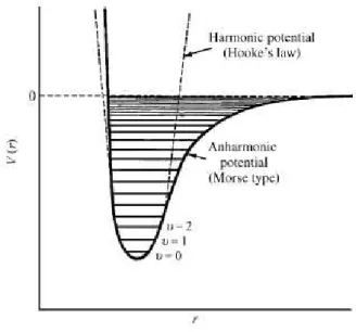
Figure 3-4 (70) Potential energy of a diatomic molecule as function of the atom’s separation with
16 between quantized vibrational energy states (Figure 3-4). When the light absorbed by the atoms
present in the sample reaches the energy difference necessary to transition between the ground
state (υ=0) and first excited state (υ=1) the FT-IR detects the decrease in light intensity that was lost to the excited atoms giving a peak in the absorbance scale [This transition is where most
vibrational modes are included and its radiation energy is in the mid-infrared spectrum (400 to
4000 cm-1)].(70) The absorbance of a sample is related to both the intensity of the background
and sample spectrums and the concentration of molecules in a sample viaBeer’s Law.(71)
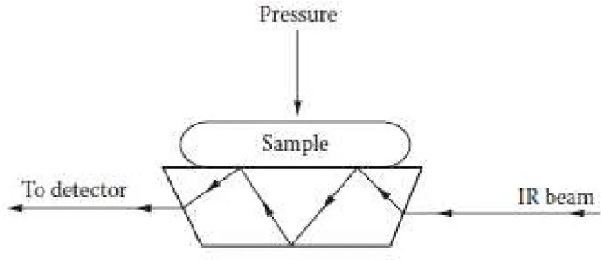
In ATR FT-IR, measuring a sample spectrum requires the use of radiation refraction
(Figure 3-5).(71) The essence of this technique relies on Snell’s law (equation 3-1) that describes the behaviour of radiation when passes from one transparent medium to another with different
refractive index.(70)
Equation 3-1 Snell’s law.
𝜂1sin 𝛳1= 𝜂2sin 𝛳2
Considering, η1the refractive index of the crystal, η2 refractive index of the sample, ϴ1
and ϴ2 the angle of incidence and refraction incidence, according to this law, it is not possible to
obtain total internal reflectance if η2 > η1. Furthermore, if we increase the angle of incidence, to a
certain angle named critical angle, ϴc, all incidence angles equal or superior to ϴc will reflect
internally as shown in figure 3-5. Despite contradictory, ATR FT-IR gives a spectrum of
absorbance just like a “normal” FT-IR spectrum even though ATR is a reflectance technique.
By combining the mechanisms of infrared identification with microscope imagining, a
new spectrum of applications can be used to uncover the composition of specific areas of the
sample that it's being measured. The combination of two techniques is named hyphenated infrared
techniques. In this case, a detector is used to draw the so-called molecular map in a grid pattern
and within in the composition identification at specific spots chosen by the operator.(71)
17
3.3
AFM
Since the invention of this technique, AFM has been a very useful tool to uncover surface
morphology and chemical to physical properties of micron-to-nano structures at an atomic and
subnanometer scale.(72)
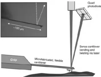
AFM as a technique works by using a sharp tip to map the surface and has it feels the
surface topology signals are sent via laser which is then reflected from the tip surface to a
photo-detector (Figure 3-6). The feedback signals are sent to a signal processing software, which
analyses and comprises a 2D or 3D plots.(72) Uncovering the surface topology can be made by
contact mode where the tip is dragged along the surface or by tapping mode which vibrates the
cantilever (object that holds the tip) at or near its resonance frequency to scan the surface. Despite
the different methods used to “feel” the surface, the local height of a surface (surface morphology
in AFM is made at each point, called pixel, of a 2D array that consists of the mapped surface) is
determined by measuring the vertical or Z displacement needed to touch the surface.(73)
Furthermore, although the principle of measuring the height of a sample is the same, different
mechanics in function of the technique are used. Looking more in-depth to the tapping mode
ability to measure the surface morphology, as it is the mechanism used in this work, this method
tracks the surface topology via amplitude of the cantilever. A Z scanner displaces at each pixel
the distance between the oscillating tip and the sample to keep the amplitude constant during
surface measurements (Figure 3-7). To obtain clear images during these experiments, the quality
of the data must provide high resolution for this effect and one factor that is crucial for this
endeavour is the precise control of the tip-surface interactions. These interactions are based on
18 continuum mechanics, long-range van der Waals forces, capillary forces, short-range forces,
electrical double layer force in a liquid, and contamination effects.(72) Each force represents a
different way that the tips interacts with the surface, and thus to produce a good atomic resolution
image the tip must be able to counteract the tip-surface interactions described above.(72)
19
Experimental methods
4.1
Materials
The following materials were purchased from Sigma-Aldrich, USA: 4
cyano-4-(phenyl-carbonothioylthio) pentanoic acid, CPAD, (>97%), 2,2′-Azobis (2-methylpropionamidine) dihydrochloride, VA-044, (97%), BIBB, (98%), pyridine (≥99%), copper(II) bromide, CuIIBr
2,
diethyl ether (DEE) (>99%), NIPAM (≥99), N,N,N’,N’’,N’’-Pentamethyldiethylenetriamine, PMDETA, (99%), and all deuterated solvents for 1H-NMR, except for chloroform-d, CDCl
3
which was acquired from Cambridge Isotope Laboratories (Inc., USA). HEMA (97%), also
purchased from Sigma-Aldrich, was purified from the oxygen inhibitor (remove the monomethyl
ether hydroquinone) by passing the polymerizable vinyl monomer through a basic alumina
(Brockmann I activated grade from Sigma-Aldrich with 50-200 µm pore size range) and filtered
through Whatman® SPARTAN® 30/0.2 RC syringe filters. Copper(I) bromide, CuIBr, was
purchased from Sigma-Aldrich as well and it was purified in glacial acetic acid (anhydrous acetic
acid). The greenish powder was stirred for at least 2 hours in acetic acid for 3 times. Afterwards,
the salt was washed with ethanol. The salt finally was filtered, rinsed three times with ethanol and
dried under vacuum overnight. The catalyst was stored in the dark and in nitrogen glove box.
Premium grade, Ensure @, solvents namely, methanol (MeOH), ethanol, acetone and DMF, were
obtained from Merck KGaA, GER and the remaining solvents THF, hexane, heptane, toluene,
chloroform, were purchased from Biosolve Chimie SARL (all belonging to Analytical grade). All
the water used was ultra-pure water dispensed through a Milli-Q system from Millipore
Corporation, USA.
Auxiliary equipment for all reactions and experiments made include VWR Blue Nitrile
powder-free disposable gloves and samples vials with snap-caps, BRAUN Sterican® needles, BD
DiscarditTM II syringes, Swann-Morton® surgical scalpel blade No.23, Eppendorf® epT.I.P.S.,
Greiner bio-one TM CELLSTAR® test tubes (to store the several inks produced), gold substrates
20
4.2
Molecular Characterization
1H-NMR spectra were acquired by Bruker Ascend 400 MHz spectrometer in deuterated
dimethyl sulfoxide (DMSO-d6) or CDCl3 solvent and ATR FT-IR spectra were measured with
Bruker Alpha spectrometer and Bruker HYPERION 1000/2000 microscope to characterize the
molecular composition of the analyte tested. Gold substrates used for ATRP macroinitiator
deposition were clean for 30 min with oxygen SPI Plasma-Prep II. The viscoelastic properties of
the produced inks were analysed with the Paar Physica UDS 200 spectrometer. MicroFab
technologies Jetlab 4 system printer permitted the defined deposition of initiator layers onto gold.
Inkjet printed ink drops of grafted ATRP macroinitiator in gold was observed with an Olympus
BX60 microscope, using 5x, 20x and 50x objective lens. Specialty Coating Systems, Inc
Spincoater® model P6700 series was to spin coat different inks in the gold substrate. Wettability
of different inks were performed with contact angle measurements (CA) from DataPhysics
contact angle system OCA. AFM instrument Molecular Force Probe 3D (MFP-3D, Santa Monica,
CA) was used to map the topography of the gold substrates.
4.3
Equipment configuration
4.3.1
Rheometer
The rheology of the inks were evaluated under conditions that simulate those of DOD
inkjet printing, using the rotational mode with parallel plate. Prior to any measurements, a
zero-gap function must be implemented to establish the limit downward dislocation that the spindle
has to do to touch the inferior plate. This function varies with the spindle used and, in our case,
we used an MP31 (50 mm, 0o) spindle. A Peltier temperature controller allowed the quick
temperature control for the measurements. The gap and temperature between the spindle and the
plate used for the rheometer test were of 0.5 nm at 25oC. After this procedure is made, the rotation
of the spindle was stabilized for 0.5 min. The viscosities were measured by applying shear rate
from 0.01 to 400 1/min with Ramp log data profile. This profile collected 100 points
(measurement duration per point of 2 s) with points taken for 200 s.
4.3.2
Inkjet Printing
Inkjet printing was set to define pre-established patterns with different configurations at
21 piezoelectric crystal is applied an external electric load. A uniform waveform with a 1 µs rise
time, varying dwell and pulses used, 1 µs fall was employed with an adjustable frequency to
obtain the best drops for each ink varying between 450 and 500 Hz. Before any experiment nozzle
purification was made with a solution of hydrogen chloride with demineralized water to clean the
nozzle.
4.3.3
Spin coating
Uniformly grafting layers were prepared by rotating the sample at 2000 Hz for 1 min. To
prevent sample displacement, the sample was put on a vacuum plate.
4.3.4
CA
Water contact values for the tested substrates were determined by adding a water drop to
the surface and calculating the angle value of the generated droplet.
4.3.5
AFM
To analyse the height and roughness of the gold surfaces a silica cantilever 2 was used. After
the cantilever was brought to its resonance frequency vibration, the drop was located and after
calibrating the laser with the cantilever surface the experiments were performed with a scan size
of 60 µs, scan rate 0.10 Hz at 15 µm/s. The amplitude was set at 19.53 mV with a frequency of
89.596 kHz.
4.4
Fabrication method
4.4.1
RAFT Polymerization of HEMA
Two 100 mL round-bottom flasks were used to perform the RAFT polymerization of the
monomer HEMA (10 mL, 0.082 mol) and the chain transfer agent, CPAD (0.0229 g, 0.82 mmol),
with VA-044 initiator (0.0133 g, 0.41 mmol), water (5 mL) and methanol (5 mL) solvent media
in a different flask. Also, DMF (1 mL) was added to the RAFT polymerization solution an internal
reference for the evaluation of the conversion via1H-NMR. The flasks were sealed with a rubber
septum and degassed by bubbling with argon gas and stirred for approximately 30 min.
22 heated up to 450C. After the desired time, the polymerization was stopped by quenching and by
allowing the reaction mixture to contact air. The precipitated polymer was purified 3 times by
precipitating in DEE. Finally, the purified polymer was dried in vacuum until all solvent and
unreacted monomer was removed as confirmed by 1H-NMR and ATR FT-IR spectra. HEMA
conversion was calculated comparing the integration areas of the monomer double bond between
6.07 and 5.62 ppm that will decrease as the monomer is converted. Purified 6th PHEMA is shown
in appendix A and the solubility table for other PHEMA of different molecular weight is displayed
in appendix B.
4.4.2
Preparation of PBIEM
A 0.397 g sample of PHEMA (-OH groups, 3.05 mmol) was dissolved in 4.90 mL of
pyridine. Then 1.402 g (6.1 mmol) of BIBB was added dropwise at 0oC in 60 min. The reaction
mixture was left to stir at the same temperature for 3h followed by stirring at room temperature
for 24 h. The insoluble salt was removed by filtration and the dissolved mixture was precipitated
in hexane. The modified polymer was dried under vacuum. After 1H-NMR analysis, an absolute
quantitative conversion was obtained as shown in figure 5-4. PBIEM physical characteristics can
23
Results and discussion
5.1
RAFT Polymerization of HEMA
RAFT polymerization technique was used to synthesise the ATRP macroinitiator. As
described in the subchapter 1.2.2, polymer chain growth occurs when degenerative chain transfer
between macro-RAFT agent and propagating radical take place so, kinetically, it is essential that
the appropriate choice of RAFT agent is made regarding the monomer as the poor choice of this
compounds, because the inherent nature of this polymerization, can lead from suppression of rate
of polymerization to uncontrolled radical polymerization resulting in broad molecular weight
polymers. For this reason, CPAD CTA (Scheme 5-1) was chosen as dithioesters are one of the
most activated RAFT agents and usual choice to polymerize methacrylate monomers as is the
case with HEMA.(74) Furthermore, the dithiobenzoyl group present in CPAD will play a critical
role in the end-use application namely self-assembly monolayers in gold. A water-soluble with a
low decomposition temperature azo initiator in VA-044 was chosen to initiate the radical
polymerization by thermal decomposition. The procedure RAFT polymerization was carried out
several times with the aim to evaluate the effect of the solvent on the length of the macromolecules
(Table 5-1). Despite imploring different reactions mixtures, the same polymeric reaction
temperature was established at 45oC. Also, the [M]:[RAFT agent]:[Initiator] ratio was maintained
Scheme 5-1 RAFT polymerization of HEMA using CPAD as the CTA.
HEMA
VA-044 in Water/Methanol 450C
24 at [1000]:[1]:[0.5] with the monomer concentration being defined at 4.1M. The change of solvent
was due to the loss of the control of the molecular weight of the synthesised polymer, i.e. it grew
so much that the solution got so dense to the point of not be physically able to stir anymore.
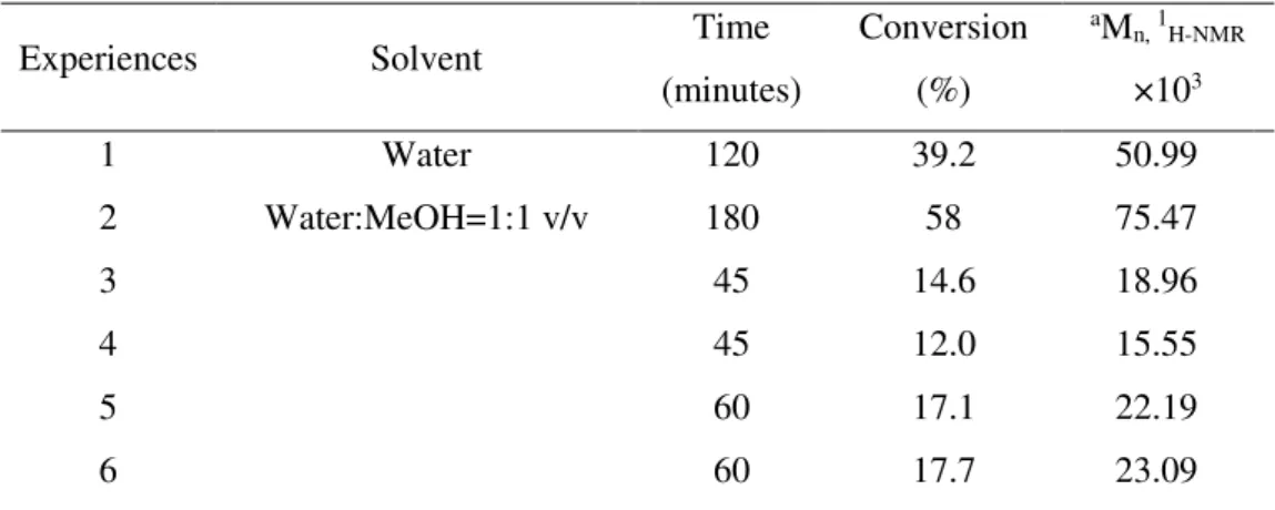
Table 5-1 Characterization of PHEMA produced.
Experiences Solvent Time
(minutes)
Conversion
(%)
aM
n, 1H-NMR
×103
1 Water 120 39.2 50.99
2 Water:MeOH=1:1 v/v 180 58 75.47
3 45 14.6 18.96
4 45 12.0 15.55
5 60 17.1 22.19
6 60 17.7 23.09
aTheoretical Number-average molecular weight calculated as: (Conversion×[M]
[RAFT agent] × MonomerMW)
A probable cause may be connected to chemical cross-linking events after termination
reaction. The selectivity of termination mechanism, suggests a recombination between active
propagating chains, as it is reported for reactions of PMMA at higher temperatures.(75) Upon
precipitation, the solution yielded two different colour polymer, namely bright pink and white.
This contrast of colours may be attributed to the different conformations of the polymer chains
formed. Since CPAD in solution has a pink colour, the precipitated white polymer must contain
a higher molecular weight than the pink polymer because of linkage between different polymer
chains which lowers even further the concentration of CAPD compared to the monomer
concentration, making it negligible. The choice of the solvent used has a deep impact on the rate
25 a h c d e b f g
constants of many homopolymerization reactions that contain monomers with hydroxy groups,
such as HEMA.(15) Since water is a bad solvent for PHEMA, the probability of termination due
to competing side reactions increase and controlled synthesis of the ATRP macroinitiator
backbone proves more challenging as to just use a cosolvent that decreases the medium polarity
slowing down the reaction to obtain better kinetics. Comparing the experiments obtained at the
same time, namely at 45 and 60 minutes, similar conversions were achieved emphasizing the
controlled nature of the chosen polymeric conditions. Linear kinetic semilogarithmic plots (figure
5-1) are shown that corroborate with the "living" polymerization mechanism of slow growth of
living chains which are the opposite of FRP. The second experience shows an inhibition time until
30 minutes that can be explained by a delay in heating the reaction mixture to the predetermined
value of 450C. Additionally, it is clear in all RAFT polymerizations the presence of an initial
phase that has practically no polymerization conversion. This induction period that occurs,
approximately, in the ten minutes of all reactions also can be explained by the heating of the
reaction mixture, however, the concept of low reinitiation rate of the leaving group should also
be considered.(76),(77) Observing the conversion over time in accordance with the solvent choice,
interesting results emerge, when at 45 min, every experiment besides the second one appears to
have faster polymerizations rates which go against what is theoretically expected.
Figure 5-2 NMR spectra of CPAD (a), HEMA (b), 6th PHEMA (c).
h g f HDO
DMSO-d6
d e
26 A reasoning for this contradiction derives from systematic data collection errors when
obtaining conversions through the 1H-NMR spectra. Figure 5-2 containing the 1H-NMR spectra
(DMSO-d6; δ ppm) of 6th PHEMA displays the typical main chain polymer peaks at: 0.70-1.00
[3H, -CH3]; 1.90 [2H, -CH2- backbone]; 2.52-2.53 DMSO-d6 solvent signal; 3.19 [3H, -CH3 from
methanol]; 3.5 water peak; 3.56-4.16 [4H, -CH2- from HEMA]; 5.21 [1H, -OH]. ATR FT-IR
spectrum (cm-1) for 6th PHEMA, displayed in figure 5-3 shows the characteristic absorption bands:
3390 cm-1[ʋ(O-H)]; 2945 and 2882 cm-1[ʋ(C-H)]; 1720 cm-1[ʋ(C=O)]; 1152 cm-1[δ(O-H)].
Additionally, the unreacted monomer band, 1634 cm-1 [ʋ(O-H)] does not appear further
confirming the purity of the synthesised polymer.
5.2
Preparation of PBIEM
The preparation of ATRP macroinitiator active sites is discussed here. As it was said in
the subchapter 1.2.3 ATR polymerization kinetics generally operates under persistent radical
effect, where a transition metal complex traps the growing propagating radical chains in a
deactivation process reaction. Because the composition of the dormant species consists of an
initiating alkyl halide it is important that the latter reactive species be able to efficiently initiate
an ATRP reaction for the selected monomer. In this sense, knowing different reactivity values of
alkyl halides is crucial for appropriate initiator choice, especially for lower targeted DPn.(34) For
the esterification reaction (Scheme 5-2), BIBB was chosen since it is a very common alkyl halide
initiator precursor for ATRP due to high reactivity rate constant values.(16) PHEMA with
different molecular weights were used to synthesize PBIEM (Table 5-2). Qualitative complete
Figure 5-3 ATR FT-IR spectra of 6th PHEMA with highlighted characteristic peaks.
ʋ( O -H) ʋ( C -H) ʋ( C = O
) δ(
O