Universidade do Minho Escola de Engenharia
Master Course in Informatics Engineering
Masters Dissertation
Easy management and user
interconnection across Grid sites
Author:
Tiago Silva e S´a
Supervised by:
Prof. Ant´onio Manuel Pina
Presentation
This document is the outcome of the last years of work I dedicated to the Masters in Informatics Engineering and also to the research projects where I was involved at the same time - namely AspectGrid, CROSS-Fire and GISELA. All these projects were centred on a common subject - Distributed Systems.
It was truly exciting to embrace such projects, expanding my knowledge about a topic that combines so many different pieces, working together to provide one of the most powerful tools in the technology world.
This document represents the last milestone on my academic path (re-gardless of what the future holds for me); hopefully a stepping stone for further developments in this area of computing science.
Acknowledgements
It is a pleasure to show my gratitude to those who made this ‘final step’ possible.
Firstly, I would like to thank Prof. Ant´onio Manuel Pina, who gave me the opportunity to join him doing research a few years ago, an opportunity that has certainly changed my academic path in a very positive way. His motivation, knowledge and comprehension were important factors in my reaching this point.
I could not forget the friends and colleagues I have had since my first day at university, both from classes and research groups, who studied and worked by my side, creating a stimulating and fun environment to grow.
Also the many great professors, who shared their knowledge and experi-ence, and all the university staff who made Braga such a splendid place to learn and live.
Lastly, and most importantly, I would like to show my love and gratitude, once again, to my family, especially my parents and my brother. Here I also include my closer, lifetime friends (you know who you are!) who play the most important role in my life. I wish I could repay everything you give me!
Abstract
Distributed computing systems are undoubtedly a powerful resource, providing functions that no other system can do. However, their inherent complexity can lead many users and institutions not to consider these sys-tems when faced by challenges posed by the deployment and administration tasks.
The first solution for this problem is the European Grid Initiative (EGI) roll, a tool that simplifies and streamlines those tasks, by extending the tools that are currently available for cluster administration to the grid. It allows the infrastructure to be easily scaled and adopted by the institutions that are involved in grid projects such as EGI.
The second part of this work consists of a platform that enables the interconnection of computing assets from multiple sources to create a unified pool of resources. It addresses the challenge of building a global computing infrastructure by providing a communication overlay able to deal with the existence of computing facilities located behind NAT devices.
The integration of these two tools results in a solution that not only scales the infrastructure by simplifying the deployment and administration, but also enables the interconnection of those resources.
Contents
List of Figures ix
List of Tables xi
1 Introduction 1
1.1 Context and motivation . . . 1
1.1.1 UMinho projects . . . 2
1.1.2 Scaling the Grid . . . 3
1.1.3 User interconnection . . . 4
1.2 Document structure . . . 5
2 State of the art 7 2.1 Introduction . . . 7
2.2 Cluster . . . 7
2.2.1 Cluster management with Rocks . . . 8
2.2.2 Other cluster management approaches . . . 9
2.3 Grid . . . 10
2.3.1 EGI project . . . 10
2.3.2 Grid Middleware . . . 12
2.4 Job Management . . . 15
2.5 Advantages and challenges of NAT . . . 16
2.6 Interconnecting hosts behind NAT . . . 17
2.6.1 NAT reconfiguration . . . 19
2.6.2 Relaying . . . 19
2.6.3 Autonomous NAT traversal . . . 20
2.6.4 Multiple techniques bundle - ICE . . . 20 vii
viii CONTENTS
2.6.5 Other real world employed techniques . . . 22
2.7 Control Information Exchange . . . 23
2.8 Moving data across the Grid . . . 26
3 Using the Cluster to Scale the Grid 29 3.1 Introduction . . . 29
3.2 EGI roll . . . 29
3.2.1 Graph-based configuration . . . 30
3.2.2 Local software repository . . . 32
3.3 gLite RPM list . . . 33
3.4 Integration . . . 35
4 Connecting users across Grid sites 37 4.1 Simple Peer Messaging (SPM) . . . 38
4.1.1 Personal Exchange for Domain Groups . . . 39
4.1.2 Point-to-Point links between remote domains . . . 40
4.1.3 Application Programming Interface . . . 41
4.1.4 Intra and Inter Domain-Group Routing . . . 42
4.1.5 SPM Port Mapper utility . . . 42
4.2 Connecting services among Grid sites . . . 42
4.2.1 Using ICE for NAT traversal . . . 45
4.2.2 Using XMPP for control information exchange . . . . 49
4.2.3 Simple Peer Messaging (SPM) . . . 50
5 Application of main results 55 5.1 University of Minho Grid sites . . . 55
5.2 SPM - performance evaluation . . . 56
5.2.1 Test-bench configuration . . . 58
5.2.2 Experimental results . . . 58
6 Conclusions and Future Work 61
List of Figures
2.1 Ganga Workflow . . . 16
2.2 General NAT concept, advantages and disadvantages . . . 18
2.3 Relaying example. The peer-to-peer connection is split into two client/server connections. . . 20
2.4 XMPP client-server, decentralised architecture . . . 25
3.1 EGI roll old graph . . . 31
3.2 EGI roll new graph . . . 32
3.3 gLite parser workflow . . . 34
3.4 EGI roll scalability. . . 36
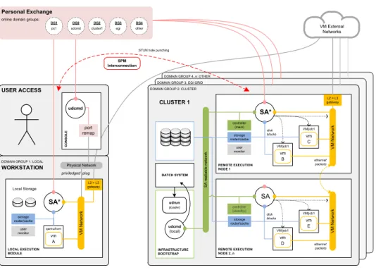
4.1 User Domains spanning multiple heterogeneous infrastruc-tures with SPM . . . 39
4.2 Typical ICE deployment scenario . . . 46
4.3 Main transport address candidates on ICE . . . 47
4.4 SPM high-level architecture. Two hosts communicating through ICE . . . 51
4.5 SPM sequence diagram. Involves ICE, XMPP and a local socket . . . 52
4.6 XMPP handshake for ICE conversation establishment . . . . 53
5.1 UMinho-CP site infrastructure . . . 56
5.2 Test setups to be used as reference . . . 57
List of Tables
3.1 The class Register holds information about each gLite node. . 35 5.1 Network bandwidth between nodes. . . 59
Chapter 1
Introduction
This chapter introduces the context in which this project was developed and the motivation behind it. Two main solutions were devised as part of the same project in order to achieve a common goal - Easy management and user interconnection across Grid sites: a) the EGI roll, which allows easy and efficient configuration, installation and maintenance of Grid sites by taking advantage of the features provided by Rocks Clusters and b) the Simple Peer Messaging (SPM) tool enables the interconnection of Grid sites (where nodes are usually on a private network), providing a user-level resource architecture, as part of the User Domains project [1].
1.1
Context and motivation
The Department of Informatics (DI) got involved in European Grid projects such as EGI, by supporting various research projects and shar-ing its resources on the Grid. Researchers involved in these projects make use of the Grid for their experiments in diverse areas, particularly in Civil Protection (CP) related activities.
The EGI infrastructure (which evolved by former projects like the En-abling Grids for E-sciencE (EGEE), as further described in section 2.3.1) is the computing and storage foundation for a great variety of research ini-tiatives. For the context of this work, it is important to mention the most relevant projects where the DI got involved. The EGI project has a main goal
2 CHAPTER 1. INTRODUCTION of providing researchers with 24 hours access to a geographically distributed computing Grid infrastructure. It is also responsible for maintaining and developing the gLite middleware[2] and operating a large computing infras-tructure for the benefit of a vast and diverse research community. This EGI site installed at the department is an essential testbed for the subjects being addressed, that allows testing of the management tools being developed.
In summary, the work being hereby presented has a main goal, repre-sented on the title of this dissertation: ‘Easy management and user inter-connection across Grid sites’. Many products and technologies have proven their value on specific tasks (e.g., deploying a computing cluster, monitoring a server), but managing a service made of a large set of smaller components is generally challenging and time consuming.
1.1.1 UMinho projects
CYCLOPS is an EU research project in the area of Grid computing that intends to bring the Grid and the Civil Protection (CP) communities closer together, making CP communities aware of the services provided by Grid infrastructures and, at the same time, making Grid researchers aware of CP specific requirements and service enhancement needs. It outlines the importance of developing e-infrastructures and virtual organisation services to fully exploit the Grid capabilities for CP applications1.
CROSS-FIRE is a project financed by the Portuguese government which aims to exploit the Grid infrastructure to demonstrate its potential through a CP activity application to be deployed among several independent CP related organisations2.
The research collaboration is not limited to Europe. The Grid Initiatives for e-Science virtual communities in Europe and Latin America (GISELA) project3, where the department is also involved, has the objective of guar-anteeing the long-term sustainability of the European Union-Latin America e-Infrastructure. For this purpose, the project focuses on two inter-related
1UMinho’s contribution to the CYCLOPS project (homepage): https://pop.cp.di.
uminho.pt/cyclops/
2
CROSS-Fire homepage: https://pop.cp.di.uminho.pt/crossfire/
3
1.1. CONTEXT AND MOTIVATION 3 goals: 1) to implement the Latin American Grid Initiative (LGI) sustainabil-ity model rooted on the National Grid Initiatives (NGI) and 2) to provide Virtual Resource Centers with the suited e-Infrastructure and application-related services required to improve the effectiveness of their research.
1.1.2 Scaling the Grid
During the development of these projects, there was the need to find a way to automatically and efficiently deploy and manage several Grid sites4, spread across different countries. This task raised special attention in the research team and motivated deeper work on the subject.
Despite improving the way Grid sites are maintained across different countries, the collaboration of the different institutions involved in these research projects has raised another concern. A Grid is intended to be used for running a high volume of jobs, normally with high computational and storage requirements. Running a simple job on the Grid requires many interactions between different services. This adds extra overhead to the process, increasing the time submitters have to wait for the results.
As part of this effort to improve the tools that are used to utilise and manage the Grid infrastructure, the team found a need to allow efficient management and scaling of the Grid sites. A solution was devised, using the Rocks Clusters management platform and its Rolls, culminating in a tool called EGI Roll.
The CP research projects, such as CROSS-Fire, demand a pool of com-puting and storage resources that can only be provided by a scalable plat-form such as the Grid, requiring a collaboration between many research institutions. However, these institutions don’t always have the personnel resources and expertise to deploy and maintain a Grid site. With that in mind, we developed a Grid site deployment and maintenance tool - the EGI roll - that makes that task easier.
However, during the development phase of an application, the code has to be repeatedly tested for debugging. Job Management tools like the ones
4A Grid site, also referred as Resource Center, is the set of Grid services provided by
4 CHAPTER 1. INTRODUCTION described in Section 2.4 can be used to increase the flexibility of these com-putational systems by allowing the developer to easily swap the endpoint where the job will run without doing major changes in the submission pro-cess.
1.1.3 User interconnection
This work is also part of a bigger research project called User Domains[1]. User Domains gathers and combines resources from multiple sources to cre-ate a per-user, geographically distributed, heterogeneous virtualisation plat-form where user-provided virtual machines can be executed in user mode (without admin privileges). To address the challenge of building a global computing infrastructure it is necessary to provide a communication overlay that is able to deal with the existence of computing facilities located behind NAT devices or firewalls.
In this work we introduce SPM (section 4.1), a simple peer-to-peer mes-saging system based on ICE and XMPP technologies, to efficiently inter-connect remote user domains[3]. Given that User Domains’ performance is highly dependent on the network characteristics and there is little work regarding NAT traversal performance, we evaluated SPM performance in multiple scenarios of interest (see section 5.2).
User Domains focus on providing uniform access to resources, rich soft-ware environments and enhanced application isolation in distributed envi-ronments. Enabled by the use of virtualisation in each of the underlying re-sources, the system maintains independence from the administrative author-ities of each infrastructure and delivers an unobtrusive user-level platform that allows the user-level execution of Virtual Machine (VM) in a batch-oriented computing cluster. A customised user-mode environment enables the user to run VMs as typical cluster jobs without imposing any persistent overhead on the execution nodes.
This work is directed towards expanding User Domains to support the interconnection of multiple infrastructures in a single user-mode computa-tion overlay through which the network traffic, storage blocks and remote user interface are directed to the intended destinations. However, most
1.2. DOCUMENT STRUCTURE 5 cluster nodes, Grid worker nodes and personal workstation that need to be connected are hidden behind NAT devices, so User Domains required an efficient method to discover and interconnect multiple entities in multi-ple, even private, locations. Without a central control point, entities must be able to autonomously become aware of each other existence in order to communicate. Moreover, there must be a basic mechanism for these peer entities to exchange control information that allows them to bootstrap more permanent, and eventually high performance, communication links.
1.2
Document structure
The rest of this document starts, in chapter 2, with a study about the state of the art - a description of the Distributed Systems environment where this work is inserted. It evaluates the current state of cluster and Grid tech-nologies and some areas that still pose challenges to users and developers.
After describing that context, we dive into the implementation of the tools that were developed to tackle the previously described problems:
• Using the Cluster to Scale the Grid - chapter 3 • Connecting users across Grid sites - chapter 4
Chapter 5 takes those tools and describes how they can be applied, depicting use cases and presenting some of the achieved testing results.
Finally, chapter 6 reserves space for the conclusions of the developed solutions and describes some areas that leave room for further improvements and enhancements.
Chapter 2
State of the art
2.1
Introduction
In this chapter we present some background information regarding the environment where Distributed System area is evolving, particularly on clus-ter and grid computing. It is also important to understand how Network Address Translation (NAT) works, the impact it has on certain applica-tions and how the posed challenges can be overcome by using NAT traversal techniques. We also narrow down on some other specific concepts and tech-nologies that serve as baseline of the solution that was developed as part of this project.
2.2
Cluster
In computing world, the term ‘cluster’ refers to a group of independent computers combined through software and networking, which is often used to run highly compute-intensive jobs. High-performance clusters have be-come the computing tool of choice for a wide range of scientific disciplines. A computer cluster is a group of linked computers, working together closely thus in many respects forming a single computer, usually deployed to im-prove performance and/or availability, while typically being much more cost-effective than single computers of comparable speed or availability. Clusters are designed to harness the power of multiple low-cost servers to provide affordable compute power for many mission-critical applications.
8 CHAPTER 2. STATE OF THE ART Computer clusters first emerged in universities and research centres, en-tities that are usually characterised by tight budgets and people with com-puter expertise.
2.2.1 Cluster management with Rocks
Setting up a computing cluster is much more than simply hooking up additional machines to a network. Somewhere, something has to set up the machines to recognise and work with each other; something has to make sure that compute tasks are assigned to the various nodes in the best fashion. A special class of middleware, which sits between the operating systems and the applications, has evolved specifically to handle these tasks, and it goes by the name of cluster management software.
Cluster management software offers an easy-to-use interface for manag-ing clusters and automates the process of queumanag-ing jobs, matchmanag-ing the re-quirements of a job and the resources available to the cluster, and migrating jobs across the cluster.
A Cluster manager usually is a backend graphical interface or command-line software that runs on the central node, working together with a cluster management agent that runs on each computing node. In some cases the cluster manager is mostly used to dispatch work for the cluster to perform. The free Rocks cluster distribution[4] takes a fresh perspective on clus-ter installation and management to dramatically simplify version tracking, cluster management and integration. This end-to-end software stack in-cludes the operating system, cluster-management middleware, libraries and compilers. Rocks centers around a Linux distribution based on the Red Hat Enterprise line, and includes work from many popular cluster and grid specific projects. Additionally, Rocks allows end-users to add their own soft-ware via a mechanism called Rolls[5]. Rolls are a collection of packages and configuration details that modularly plug into the base Rocks distribution. The traditional Rocks architecture, used for high-performance computing clusters, favours high-volume components that lend themselves to reliable systems by making failed hardware easy and inexpensive to replace.
2.2. CLUSTER 9 any desired rolls. They serve as login and compile hosts for users. Compute nodes typically comprise the rest of the cluster and function as execution nodes.
Rocks has been successfully used to manage large clusters consisting of hundreds of nodes. Included in the standard Rocks distribution are vari-ous open-source high-performance distributed and parallel computing tools, such as Sun Grid Engine (SGE), OpenMPI and Condor. This powerful col-lection of advanced features is one reason why NASA, the NSA, IBM Austin Research Lab and Harvard, among other institutions, are all using Rocks for some of their most intensive applications.
On this work, we decided to use Rocks clusters as the management soft-ware, for it’s a massively adopted tool and also because it is the system currently being used on the department as the cluster management tool of choice.
2.2.2 Other cluster management approaches
There are other tools that also play an important role on cluster admin-istration.
Open Source Cluster Application Resources (OSCAR)1 was created in 2000 by a group of organisations when it became apparent that assembling cluster software from many components was challenging and tedious. This group decided to choose ‘best practices’, selected among the many open-source solutions and include them in a software stack so as to make the installation, configuration and management of a modest-sized cluster easier. OSCAR is a bit different in that it installs on top of a standard installation of a supported Linux distribution. It then creates customised disk images used to provision the nodes.
Also worth mentioning is Warewulf2, developed by the Scientific Cluster Support Program at the Lawrence Berkeley National Laboratory. This open-source toolkit is similar in many ways to Rocks and OSCAR. It works by allowing compute nodes to boot a shared image from a master node so that a systems administrator only needs to support the master node and the
1
OSCAR project homepage: http://svn.oscar.openclustergroup.org/trac/oscar
2
10 CHAPTER 2. STATE OF THE ART shared image for the rest of the system. Note that starting with Warewulf 3, cluster-provisioning features have been replaced by a project called Perceus.
2.3
Grid
Grid computing has emerged as an important new field, distinguished from conventional distributed computing by its focus on large-scale resource sharing, innovative applications, and, in some cases, high-performance ori-entation.
The Grid can be thought of as a distributed system with non-interactive workloads that involve a large number of files. What distinguishes grid computing from conventional high performance computing systems, such as cluster computing, is that grids tend to be more loosely coupled, heteroge-neous, and geographically dispersed. Although a grid can be dedicated to a specialised application, it is more common that a single grid will be used for a variety of different purposes. Grids are often constructed with the aid of general-purpose grid software libraries, or middleware.
The distributed computing grid was originally conceived in 1999 to anal-yse the experimental data produced by the Large Hadron Collider (LHC)3 at CERN – the European particle physics laboratory located on the Swis-s/French border4.
2.3.1 EGI project
The European Grid Initiative (EGI) project, launched in May 2010, is a collaboration between National Grid Initiatives (NGIs) and other European international research organisations. The main goal of this pan-European infrastructure is to provide scientists a powerful set of computational tools, where they can take their research activities.
The European DataGrid Project5, which started in January 2001, led the research and development of Grid technologies. It established the or-ganisational structure, gathered and analysed requirements, developed
mid-3
About the LHC project: http://public.web.cern.ch/public/en/LHC/LHC-en.html
4
More about CERN: http://public.web.cern.ch/public/
5
2.3. GRID 11 dleware (the software that links hardware resources), and provided training to its users. The project proved the Grid’s successful application in various research fields such as high energy physics, Earth observation and bioinfor-matics.
Upon completion in March 2004, a new project called Enabling Grids for E-sciencE (EGEE)6took over the Grid’s further development in what would result in three successive two-year phases. EGEE provided researchers with access to computing resources on demand, from anywhere in the world and at any time of the day. Ease of access and the ability to analyse a larger amount of data within a shorter timescale than before attracted participation from a wider range of scientific disciplines.
By April 2010, when the last EGEE project phase was completed, a new project took over - the EGI, a sustainable project that links more than 18,000 researchers (and counting) to the distributed computing electronic resources (computing and storage) they need for their work.
In other words, EGI provides a production quality Grid infrastructure distributed among most European countries (including Portugal). EGI is open to new sites that want to join the infrastructure and offer their re-sources, sharing more power to the community. However, since EGI is a production quality infrastructure, several administrative and technical pro-cedures exist, to ensure that a new site that is being integrated in the infras-tructure will be able to meet certain quality criteria. So, before entering into production, a site must pass a set of specific registration and certification steps.
Each NGI groups a set of institutions among a geographical region, com-monly formed by one or more countries. Portugal and Spain have joined their efforts in a single NGI called Ibergrid. Each NGI integrates a Regional Operation Centre (ROC), responsible for the sites operating in its region. Notably, a ROC is committed to provide know-how, advice and support to the sites for the resolution of possible installation and operational issues. It ensures that the sites get adequate support during deployment and op-erations and that the operational procedures are enforced within the whole
6
12 CHAPTER 2. STATE OF THE ART NGI.
2.3.2 Grid Middleware
A Grid middleware is a software tool that provides an abstraction layer between physical resources, even when provided by different vendors and operated by different organisations, and applications or users. It facilitates interoperability among Grid services and provides a simplified user inter-face that ultimately improves utilisation and adoption. In order to address the end-user requirements, the services need to work together in a coordi-nated manner, although individual services can still be deployed and used independently.
The gLite middleware7 is an example of such a tool, currently installed in hundreds of sites participating in the EGI. gLite provides the necessary tools and configurations that allows a seamless integration of heterogeneous clusters in the EGI infrastructure. The middleware includes services and components addressing four technical areas:
Compute: processing and management of user requests concerning the ex-ecution of a computational task. Covers the interaction with Local Resource Management System (LRMS), the provision of a common interface to the computational resources of a site (the so-called Com-puting Element) and the availability of high-level meta-scheduling, workflow execution and task tracking functionality.
Data: storage management, data access and data replication. Multiple storage solutions exist, addressing different types of resources – disk, tape or a combination of the two – all exporting the same Storage Resource Manager (SRM) interface (the so-called Storage Element). Data access libraries are available for storage systems not offering a POSIX interface towards the computational resources. Data and metadata catalogues track the location of copies of data chunks in multiple places.
Security: enable and enforce the Grid security model, allowing the safe
7
2.3. GRID 13 sharing of resources on a large scale. They cover identity manage-ment, Virtual Organization membership managemanage-ment, authentication, delegation and renewal of credentials, and authorisation.
Infrastructure: information and management functionality to deployed Grid services. They include the Information System and Service Reg-istry, which provide a view of the services available on the Grid to-gether with their characteristics; the messaging infrastructure, that allows to collect and distribute messages generated by Grid services or user tasks; the service monitoring and management providers that allow the retrieval of Grid services status information and service state management; the Logging and Bookkeeping services that allows col-lecting, aggregating and archiving job execution information; the ac-counting functionality to collect, distribute and publish information concerning the usage of resources This area also deals with internal in-frastructure components, such as service containers that are required for middleware services.
In practical terms, it consists in a set of packages that define the different roles of computers in a cluster wishing to become part of the EGI grid[6]. Among these roles (called elements in the gLite’s terminology), one can commonly find in a Grid site:
Computing Element (CE) responsible for the management of the sub-mitted jobs and for the local resource management system (LRMS) Storage Element (SE) provides uniform access to data storage resources.
The Storage Element (SE) may control from simple disk servers to large disk arrays. Most EGI sites provide at least one SE which can support different data access protocols and interfaces
Accounting Processor for Event Logs (APEL) an accounting tool that collects accounting data from participating sites
Berkeley Database Information Index (BDII) responsible for the in-formation system. It collects inin-formation from the site elements (such as number of CPUs, available storage, available services) and makes it available to be queried from the outside
14 CHAPTER 2. STATE OF THE ART Worker Node (WN) computing units with the processing power to
exe-cute the jobs
User Interface (UI) the access point to the grid. From a UI, a user can be authenticated and authorised to use the EGI resources, and can access the functionalities offered by the Information, Workload and Data management systems. It provides CLI tools to perform Grid operations.
In the EGEE era, the middleware development and the infrastructure operation was handled inside the same European project - as the gLite middleware was developed by the EGEE project. With the end of EGEE, different projects have emerged raising a different paradigm with respect to what was done in the past.
Under the new context, the operation of the infrastructure and the devel-opment of the middleware are responsibilities of different European projects. EGI and NGIs, and the communities using the grid infrastructure, are now assuming a client role, installing products from Technology Providers such as European Middleware Initiative (EMI).
The products developed by these external Technology Providers (i.e. EMI) have to fulfil a given set of quality criteria defined by EGI, and only the products which are properly verified and checked against the EGI qual-ity criteria can integrate a Unified Middleware Distribution (UMD) release. The proposed approach of handling middleware maintenance, integration, testing, and deployment within the EGI infrastructure. UMD defines com-ponents, processes, involved parties, and so on, in order to guarantee the infrastructure to get reliable middleware, in terms of both functionality and quality. Under the current approach, a product can be release in EMI, for example, but never reach to integrate a UMD release.
The gLite middleware, originally produced by the EGEE project, is cur-rently being developed by the EMI project, a Technology Provider. The EMI project aims to deliver a consolidated set of middleware products based on the four major middleware providers in Europe - ARC, dCache, gLite and UNICORE. The products, managed in the past by these separate providers, are now developed, built and tested in collaboration, for deployment in EGI
2.4. JOB MANAGEMENT 15 (as part of the UMD), and other distributed computing infrastructures.
The migration from former packages like gLite to the UMD is being enforced at the time of writing. Different NGIs devised an action plan that has to be applied by all the participating Grid sites, in order to ensure a seamless transition to the new platform.
2.4
Job Management
Scientific users are driven by a requirement to get computing results quickly and with minimal effort. These users have a wide variety of com-puting resources at their disposal, namely workstations, batch systems and computing Grids.
Each of these resources has a unique user interface and users have the burden of continually reconfiguring their applications to take advantage of the diverse systems.
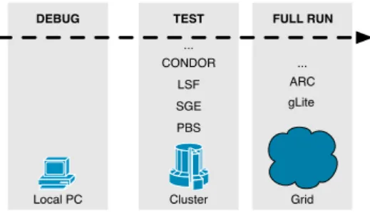
Ganga Ganga[7] is a modular, user-friendly job management tool for sci-entific computing that supports an extensible suite of execution backends, allowing users to easily run jobs on their local workstation, on a number of batch systems and many Grid platforms. This situation is shown in Listings 2.1. The first line shows the command that lists the installed backends, de-pending on the experiment specific plugins that were loaded. The last three lines show an example about how to specify the desired backend, in this case: Local (run jobs in the background on local host), PBS (submit jobs to Portable Batch System) and LCG (submit jobs to the EGI/LCG Grid using gLite/EDG middleware).
Listing 2.1: Ganga usage example
I n [ 1 ] : p l u g i n s ( ” b a c k e n d s ” )
Out [ 1 ] : [ ’ LSF ’ , ’ Remote ’ , ’PBS ’ , ’ Condor ’ , ’SGE ’ , ’ Batch ’ , ’LCG ’ , ’ L o c a l ’ , ’ I n t e r a c t i v e ’ ]
I n [ 2 ] : j o b=Job ( a p p l i c a t i o n=E x e c u t a b l e ( e x e= ’ / b i n / hostname ’ ) ) I n [ 3 ] : j o b . backend= ’ L o c a l ’ #j o b . backend= ’PBS ’ #j o b . backend= ’LCG ’ I n [ 4 ] : j o b . submit ( )
16 CHAPTER 2. STATE OF THE ART The typical workflow of Ganga is illustrated in figure 2.1. Users can easily plug new modules to suit their needs. They can develop and debug on the local workstation, then test on a batch system and finally run a full analysis on one of the many Grids.
Local PC Cluster Grid
PBS SGE LSF
DEBUG TEST FULL RUN
CONDOR
gLite ARC ...
...
Figure 2.1: Ganga Workflow
2.5
Advantages and challenges of NAT
The Internet’s original uniform address architecture, in which every node had a globally unique IP address and could communicate directly with every other node, has been replaced with a new real Internet address architecture, consisting of a global address space ‘separated’ from many private address ones.
Minor portions of the IPv4 address space have been allocated or assigned directly by the Internet Assigned Numbers Authority (IANA)8 for global or other specialised purposes, namely for private addressing[8]. Routers are required to interconnect different networks, regardless of whether the IP address range is public or private. However, if the address range is private, packets cannot be directly routed across the public Internet.
In the present, most networks use NAT to address this ‘issue’ and it is estimated that more than 73% of the hosts are behind NAT devices[9]. This was not a problem in the past, when most communication was based on the client/server paradigm. However, the Internet has evolved and, nowadays, the largest portion of the traffic comes from peer-to-peer (p2p) applications. Applications such as p2p file sharing, VoIP services and the online services
8
2.6. INTERCONNECTING HOSTS BEHIND NAT 17 of current generation require clients to be servers as well, thereby posing a problem for users behind NAT devices, as incoming requests cannot be easily correlated to the proper internal host, potentially requiring substitution or special traversal techniques for NAT traversal.
Basically, NAT is the process of transparently modifying IP address in-formation in IP packet headers, while in transit across a routing device (see figure 2.2a). Traditional NAT[10] has two variations, namely, Basic Network Address Translation and Network Address Port Translator. The latter, Network Address Port Translator (NAPT)[11] is by far the most com-monly deployed NAT device as it allows multiple private hosts to share a single public IP address simultaneously.
The main advantages of NAT are that private IP addresses can be re-used and many hosts on a single LAN can share globally unique IP addresses, improving the scalability of the address space and helping to overcome the shortage of unique public addresses in IPv4. NAT operates transparently and helps shield users of a private network against access from the public domain, hiding private IP addresses from public networks. NAT operates much like an Access Control List (ACL), not allowing outside users to access internal devices. This control of both inbound and outbound traffic can be seen as an advantage, providing a level of security.
On the other hand, one disadvantage is that additional configuration is required to allow access from legitimate, external users or p2p applications. Also, it may impact on some applications that have IP addresses in their message payload, because these IP addresses must also be translated. Figure 2.2b summarises the main advantages and disadvantages of NAT.
2.6
Interconnecting hosts behind NAT
Many techniques exist for NAT traversal, relying on different methods and tools, that make these connections to hidden hosts possible. However, the success rate of different techniques depend on the NAT device being used and their the implementation can be complex. Most of the NAT traversal solutions are either part of proprietary applications or nested in the ap-plication code. Unfortunately, there is not a single technique that works
18 CHAPTER 2. STATE OF THE ART Internet NAT Pu b lic In te rn e t G lo b a l IPs L o ca l N e tw o rk Pri va te I Ps (a) Concept
Advantages of NAT Disadvantages of NAT
• Public IP address sharing • Transparent to end users • Improves security and
scalability
• Incompatible with certain applications
• Hinders legitimate remote access
• Increased routing processing
(b) Advantages and disadvantages of NAT
Figure 2.2: General NAT concept, advantages and disadvantages
with all existing NATs, because NAT behaviour is not standardised. There are studies determining average success rates using different methods and tools[12, 13].
Although the rules of the game are changing, with the actual migration from IPv4 to IPv6 [14, 15], eventually reducing the need for NATs connect-ing private hosts to the Internet, the demand for NAT will be increasconnect-ing in the near future because NAT itself provides the easiest way to achieve interoperability between both versions of the IP [11]. Additionally, the mi-gration is today an hot topic where opinions diverge. Some say that the total transition will never occur.
Internet Engineering Task Force (IETF) published the informational Re-quest For Comment (RFC) 5128 in 2008, documenting the various AT traver-sal methods known to be in use by that time[16]. It covers NAT travertraver-sal approaches, used by both TCP-based and UDP-based applications. An ef-fort was made to keep this text as coherent as possible with the terminology and conventions used on that document.
Several non-proprietary solutions have been proposed to allow network protocols to operate through NATs focused particularly on the UDP traf-fic required to address the widely used VoIP and file sharing peer-to-peer applications. IETF has even published RFCs 3489, 5128, 5245, 5389 and 5766 regarding NAT traversal approaches, including support for TCP appli-cations.
The success rates using different methods and tools in multiple network configurations were presented in [8, 9], where it can be verified that
com-2.6. INTERCONNECTING HOSTS BEHIND NAT 19 plexity of the network topologies largely determines each techniques’ degree of success. So, there is no universal NAT traversal solution, but several tech-niques that can be used together depending on the network configuration.
2.6.1 NAT reconfiguration
NAT traversal strategies such as Network Address Translation-Port Map-ping Protocol (NAT-PMP), Universal Plug and Play (UPnP) work with a reconfiguration of the router/NAT device, involving explicit signalling be-tween applications and NAT devices. These methods are not always an alternative because, under certain network administration environments, a common privileged user may be prohibited to change the NAT configuration due to security concerns. Moreover, the NAT device may not even support these functionalities.
For these reasons, NAT reconfiguration strategies cannot be completely trusted as a failsafe solution.
2.6.2 Relaying
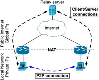
Relaying is the most reliable method for implementing p2p communica-tion across NAT devices, but the least efficient too. This method breaks a peer-to-peer communication into two standard client/server communica-tions, through a relaying server with a publicly addressable IP address (see figure 2.3). This method will always work, as long as both clients are able to connect to the server. The big disadvantage is that all the traffic is routed through the relay server, consuming the server’s processing power and network bandwidth, and increasing the latency of the communication. However, this strategy can be useful as a fall-back when there is not a more efficient alternative and if maximum robustness is required. The Traversal Using Relays around NAT (TURN) protocol [17] defines a method of imple-menting application agnostic, session-oriented, relaying in a relatively secure fashion.
20 CHAPTER 2. STATE OF THE ART A B NAT Pu b lic In te rn e t G lo b a l IPs L o ca l N e tw o rk Pri va te I Ps Relay server Internet P2P connection Client/Server connections
Figure 2.3: Relaying example. The peer-to-peer connection is split into two client/server connections.
2.6.3 Autonomous NAT traversal
This novel technique presented in [18] provides an autonomous method for establishing connections to peers behind NAT without reliance on a third party server. Using third parties increases the complexity of the software and potentially introduces new vulnerabilities. Technically, this method uses fake ICMP messages to initially contact a peer behind a NAT.
This strategy works best if only one of the hosts is behind a NAT device. In that case, it is assumed that the client has somehow learned the current external IP address of the server’s NAT (i.e. from a previous connection between the two hosts or by exchanging that information using other out-of-band methods). Further complications arise if both hosts are behind NAT, depending on its type (RFC 3489 specifies four NAT variations[19]).
2.6.4 Multiple techniques bundle - ICE
Traditional NAT traversal methods require the help of a third party server (also known as rendezvous server) with a publicly addressable IP ad-dress for facilitating the connection[20, 17]. Some methods use the server only when establishing the connection, while others are based on relaying all
2.6. INTERCONNECTING HOSTS BEHIND NAT 21 data through it, which adds bandwidth costs and increases latency, detri-mental to real-time voice and video communications. In a few words, the basic approach in most of these cases is that the server in the private net-work behind the NAT is notified by the third party that the client would like to establish a connection. In order for this method to succeed, the server must maintain a connection to a third party known service, the client must also be able to locate that broker, which must act according to a specific protocol.
A method known as hole punching is one of the most effective for es-tablishing peer-to-peer communication protocols between hosts on different private networks behind NAT. This technique was firstly designed for UDP-based applications, but can also be applied for TCP[12].
Interactive Connectivity Establishment (ICE)
As described above, numerous solutions exist allowing protocols to op-erate through NAT. Unfortunately, these techniques all have pros and cons, which make each one optimal in some network topologies, but a poor choice in others. By using them, administrators are making assumptions about the networks’ topologies in which their solutions will be deployed and intro-ducing greater complexity into the system. It is necessary to find a single solution that is flexible enough to work well in all situations.
RFC 5245, published by IETF in April 2010, defines Interactive Connec-tivity Establishment (ICE) as a technique for NAT traversal for UDP-based media streams (though ICE can be extended to handle other transport pro-tocols, such as TCP) established by the offer/answer model[21]. ICE works by including multiple IP addresses and ports in offers and answers, which are then tested for connectivity by peer-to-peer connectivity checks. The IP addresses and ports included in the connection offer and the connectivity checks itself are performed using the revised STUN specification [20], now renamed to Session Traversal Utilities for NAT. This name and specification revision reflects STUN’s new role as a tool that is used with other NAT traversal techniques (namely ICE) rather than a standalone NAT traversal solution, as the original STUN specification was.
22 CHAPTER 2. STATE OF THE ART In a typical ICE deployment, we have two endpoints (known as agents) that want to communicate. They are able to communicate indirectly via some signalling protocol (see section 2.7), by which they can perform an exchange of messages. At the beginning of the ICE process, the agents have no information about the network topology. They might not even be behind a NAT. Using ICE, agents can discover enough information about their topology to potentially find one or more paths by which they can communicate.
2.6.5 Other real world employed techniques
NAT traversal is currently a hot topic, due to the change on the commu-nications paradigm (moving from client/server to peer-to-peer). Although there is a big effort to standardise the protocols and techniques, there is not a single, infallible solution to solve this problem with all existing NATs implementations. Generally, the solution is to try different strategies until the working one is found.
This may sound strange when we have plenty of successful p2p applica-tions such as VoIP (e.g. Skype), online games, p2p file sharing (e.g. BitTor-rent), p2p streaming (e.g. PPLive) that have become tremendously popular. So, how do they overcome the NAT traversal problem? The answer is not always easy to find because these solutions are either part of closed, proprietary applications, or nested in the application code itself. Some of these popular p2p applications are described bellow.
Skype9, is a good example of a popular Voice over IP (VoIP) p2p appli-cation, claimed to work almost seamlessly across NATs and firewalls, with good voice and video quality. Although users may find it very similar to other clients such as MSN messenger10 and Google Talk11, the underlying protocols and techniques it employs are quite different[22].
Skype could not work properly without efficient NAT and firewall traver-sal functions. According to the study by Baset and Schulzrinne[22], each Skype client uses a variant of Session Traversal Utilities for NAT (STUN)[20]
9
Skype homepage: http://www.skype.com
10
MSN messenger: http://messenger.msn.com
11
2.7. CONTROL INFORMATION EXCHANGE 23 and TURN[17] protocols to determine the type of NAT and firewall it is be-hind. Also, these authors believe that ‘it is by the random selection of sender and listener ports, the use of TCP as voice streaming protocol, and the peer-to-peer nature of the Skype network, that not only a Skype client traverses NATs and firewalls but it does so without any explicit NAT or firewall traversal server’. Ahmed and Shaon also have an interesting pub-lication on this topic[23], evaluating popular VoIP services (mainly Skype, GTalk and Gizmo).
Spotify12 is a popular music streaming service with more than ten mil-lion users. It uses a hybrid communications architecture, composed by both client-server streaming and a client p2p network overlay in order to offload the central servers. This p2p network requires a connection between clients, generally behind NAT devices. Goldmann and Kreitz recently conduced a study where, among other measurements, they describe the NAT traversal strategy employed in that application[24]. According to the authors, the Spotify client application uses two NAT traversal methods: a) NAT recon-figuration methods such as UPnP and NAT-PMP to open a port for incom-ing connections, as described in section 2.6.1 and b) various hole punchincom-ing techniques, described in section 2.6.4.
Our conclusion is that these valuable networking features, implemented by every big company dealing with p2p applications, are well protected and patented. So, the alternative for a researcher with a quite shorter budget is to stick with the public standards, specifications and frameworks.
2.7
Control Information Exchange
This section describes the solution for indirectly exchanging control in-formation to interconnect different devices. As described in section 2.6, while client/server model has a stable behaviour across the internet, the increasingly important p2p model sometimes raises significant problems on the presence of NAT devices.
We previously discussed different methods and solutions to overcome those problems. Among those, the most flexible and resilient solution is
12
24 CHAPTER 2. STATE OF THE ART the use of ICE (further described in section2.6.4). However, to be able to establish a direct p2p connection between two hosts using this technique, we must firstly be able to exchange calling/control information between them. This task falls on a different field of communication protocols, where many alternatives exist. Session Initiation Protocol (SIP) and XMPP are just two of the various possibilities.
XMPP Extensible Messaging and Presence Protocol (XMPP) is a widely deployed open technology for real-time interaction, using Extended Markup Language (XML) as the base format exchanging information. Although common users don’t notice it, XMPP is under the hood of massive com-munication services used worldwide like Google Talk. Another important feature is its security. It provides built-in support for encryption and strong authentication. The fact that XMPP technologies are deployed in a decen-tralised client-server architecture with an unlimited number of servers also improve its security and scalability, since there is no single point of failure. Any person or organisation can run their own XMPP server and connect it to the rest of the network using the Internet infrastructure.
XMPP is, at its core, a technology for rapidly delivering XML between clients, being used for a wide range of applications beyond instant messag-ing, including gammessag-ing, social networkmessag-ing, VoIP, real-time collaboration and custom applications. Also, it is a standard. Its core aspects have undergone rigorous public review within the IETF, resulting in strong technologies that can be freely implemented under any licensing terms.
As you can further read on [25], these and other aspects make more and more software developers and service providers adopt this technology on their projects to solve real-world problems.
Among core services such as channel encryption, authentication, con-tact lists messaging and notifications, XMPP enables peer-to-peer media sessions. This service, defined in XEP-0166 allows to negotiate and manage a media session with another entity, for the purpose of voice chat, video chat, file transfer and other real-time interactions.
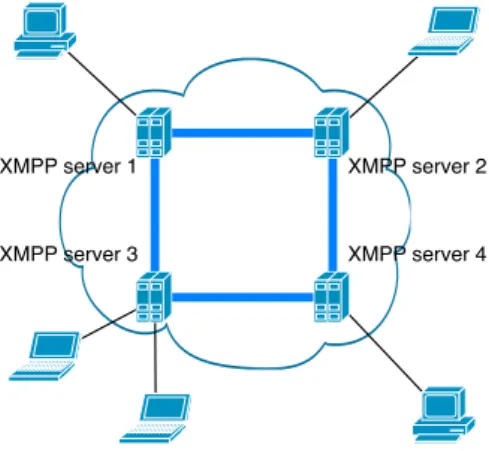
XMPP technologies use a decentralised client-server architecture, as de-picted in figure 2.4, where we can have several clients communicating, using
2.7. CONTROL INFORMATION EXCHANGE 25 a network of servers. XMPP server 1 XMPP server 3 XMPP server 2 XMPP server 4
Figure 2.4: XMPP client-server, decentralised architecture
Like email, when a XMPP message is sent to a contact on a different domain, the client connects to its ‘home’ server, which then connects directly to the other contact’s server, without intermediate hops.
Every XMPP entity needs and address, called JabberID (JID), contain-ing a domain portion which can be resolved through DNS and a username portion that identifies the user itself. Additionally, when a client connects to a XMPP server, it can choose (or be assigned by the server) a resource identifier for that particular connection. As an example, the JabberID ‘[email protected]/mobile’ is divided in tree parts: username, domain and resource.
XML stanzas can be thought of as the basic unit of communication, sim-ilar to packets or messages in other network protocols, in XMPP. There are three kinds of stanzas (Message, Presence and IQ), that can carry different meanings, attributes and payload definitions.
These stanzas are exchanged asynchronously with other entities on the network. This event-driven approach has a number of advantages, such as real-time notifications and the ability to work around the need to continually poll for updated information.
XMPP reaches beyond the instant messaging realm; it is now applied to a range of applications, including gaming, social networking, VoIP, real-time collaboration and custom applications. XMPP technologies are hosted
26 CHAPTER 2. STATE OF THE ART in decentralised client-server systems with an unlimited number of servers thus providing security and scalability and there is no single point of failure.
2.8
Moving data across the Grid
gLite, the grid middleware currently installed in UMinho’s Grid sites, has many different tools that can be used to move data across different devices.
A Storage Element (SE) provides uniform access to data storage re-sources in the EGI (most sites provide at least one SE), allowing a user or an application to store data for future retrieval. It may control simple disk servers, large disk arrays or tape-based storage systems.
SEs can support different data transfer and access protocols. In sum-mary, the protocols supported in gLite 3.2 are [6]:
GSIFTP - a Grid Security Infrastructure (GSI) secure FTP protocol for whole-file transfers. It is responsible for secure file transfers to/from SEs. Every EGI site runs at least one GSIFTP server.
RFIO - offers direct remote access of files stored in the SEs in a secure and an insecure version
gsidcap - GSI enabled version of the dCache native access protocol. file - used for local file access to network filesystems.
Most storage resources are managed by a SRM13, a middleware service providing file handling capabilities. Any type of Storage Element in EGI offers an SRM interface except for the Classic SE, which was phased out. However, SRM implementations from different storage system may differ and offer different capabilities. There are different storage systems used in EGI. As an example we have: Disk Pool Manager (DPM), used for for SEs with disk-based storage only; CASTOR, designed to manage large-scale mass storage systems, with front-end disks and back-end tape storage; and StoRM. SRM hides the complexity of the resources setup behind it and allows the user to request files, keep them on a disk buffer for a specified lifetime, reserve in advance space for new files, and so on. SRM offers also
13
2.8. MOVING DATA ACROSS THE GRID 27 a third party transfer protocol between different endpoints, not supported however by all SE implementations. It is important to notice that the SRM protocol is a storage management protocol and not a file access protocol.
Chapter 3
Using the Cluster to Scale
the Grid
3.1
Introduction
In line with the R&D projects in which University of Minho is involved, a method to hasten the installation and administration process of an EGI site was developed. This method is based upon Rocks, a RedHat Enterprise Linux based distribution that aims at an easy installation and administration of computer clusters.
3.2
EGI roll
The EGI roll intends not only to make de installation of a Grid site easier, but also to simplify its administration. A former team mate, Bruno Oliveira, developed a set of features to provide administrators an intuitive and easy to use tool to perform the most common administration tasks, including management of the site’s configuration, virtual organisations and software updates[26].
With hundreds of deployed clusters, Rocks’ approach has shown to be quite easily adapted to different hardware and logical node configurations. However, the Rocks architecture and implementation contains a significant asymmetry: the graph definition of all appliance types except the initial FE
30 CHAPTER 3. USING THE CLUSTER TO SCALE THE GRID can be modified and extended by the end-user before installation. To address this administrative discontinuity between nodes and FEs, rolls were designed and implemented. Rolls provide both the architecture and mechanisms that enable the end-user to incrementally and programmatically modify the graph description for all appliance types. New functionality can be added and any Rocks-supplied software component can be overwritten or removed. This approach to cluster construction has allowed to shrink the core of the Rocks implementation while increasing flexibility for the end-user. Rolls are op-tional, automatically configured, cluster-aware software systems. Current add-ons include: scheduling systems (SGE, PBS), Grid Support, Database Support, Condor, just to name a few. Community-specific rolls can be and are developed by groups outside of the Rocks core development group.
3.2.1 Graph-based configuration
The Rocks toolkit (section 2.2) uses a graph-based framework to describe the configuration of all node types (known as appliances) that make up a complete cluster.
Rocks offers system administrators the ability to customise the packages to be installed by creating rolls, and to create dependencies between them using a graph-based framework. Some graph nodes are used to specify an appliance, which represents a particular computer node role or type. In order to be as flexible as possible, Rocks creates the kickstart on demand based upon a graph representation of the dependencies between packages or services[27].
The graph representations express both the set of packages to be installed and the individual package configuration. Each vertex of the graph repre-sents a package or a service and its configuration. Both graphs and nodes are described by xml files. The graph file specifies the framework hierarchy where edges connect nodes to each other and each node file contains a list of Red Hat packages and optional configuration scripts to turn a meta-package into a final software deployment. Along with the packages configuration, the installation process can run pre- and/or post- install scripts that have access to a global configuration MySQL database managed by the FE that
sup-3.2. EGI ROLL 31 ports complex queries. The configuration of a cluster can then be thought of as a program used to configure a set of software, whose state, that rep-resents a single instantiation of a cluster appliance, may be referenced by XML configuration code.
Taking the graph approach, nodes installation can be easily extended by creating a new graph that adds an arc linking to the extended node. Once the node file is created and packages are placed in the file installation hierarchy tree, other appliances derived from the newly created node can be added to the site.
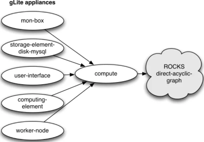
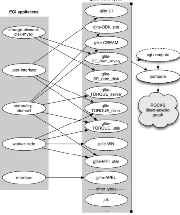
As part of this work, the roll was changed to accommodate the recent changes in the middleware system. Previously, each gLite appliance used to be an extension of the Rocks compute appliance, as shown in figure 3.1. However, on the upgrade to gLite 3.2, it was required to adapt those appliances and create additional ones. Plus, some of the EGI appliances share common packages. For that reason, we decided to create a layer of gLite node types, that inherit from the traditional Rocks compute node, and group those node types to form the final EGI appliances. This new graph structure, which is easier to adapt and maintain, is depicted in figure 3.2.
ROCKS direct-acyclic-graph compute mon-box storage-element-disk-mysql user-interface computing-element worker-node gLite appliances
32 CHAPTER 3. USING THE CLUSTER TO SCALE THE GRID ROCKS direct-acyclic-graph compute mon-box storage-element-disk-mysql user-interface computing-element worker-node
EGI appliances glite-UI
gLite node types
glite-BDII_site glite-CREAM glite-SE_dpm_mysql glite-SE_dpm_disk glite-TORQUE_client glite-TORQUE_server glite-TORQUE_utils glite-WN glite-MPI_utils glite-APEL ---other types---jdk ... egi-compute
Figure 3.2: EGI roll new graph
3.2.2 Local software repository
One aspect that cannot be overlooked in the maintenance of a cluster is software updates. In a site with a significant number of nodes, this task can rapidly drain the available bandwidth and can represent a bottleneck in the system. The EGI roll gives system administrators the possibility to create a local repository of the software, so nodes can update themselves locally. This repository is created using the mrepo package1. The local repository holds a copy of the three major components in the EGI site: Scientific Linux, DAG and gLite middleware.
When installing the roll, system administrator can choose between the local repository or the normal repositories for the software. The creation of the local repository is time and hard-disk space consuming, but in the long run, this solution pays-off, since only one machine, the FE, has to fetch the
1
3.3. GLITE RPM LIST 33 updated packages from the Internet, in a completely transparent automatic process, dealt by mrepo.
3.3
gLite RPM list
The rocks command, that is available in Rocks clusters, aims to merge under it all cluster administration tasks, that were scattered in several dif-ferent commands. It is not about new commands, but a way to simplify the interface to tasks already offered, with an easy to use and understand syntax. The rocks command is based in verbs, like add, set, activate, list, among others.
Taking the rocks command as its base, the egeecli command was created to offer a clean and easy to use syntax to perform the administration tasks on a EGI site[26]. Particularly, it allows administrators to easily apply the frequently released updates of the gLite middleware, which provide new functionalities and bug fixes. That update process can take several steps, that involve not only the installation of the update via yum – or apt, in the case of a Debian environment – but can imply changes to the gLite configuration files, replication of these files and reconfiguration, via YAIM2. To aid administrators in the process, the egeecli command has adapted several verbs and created special objects that, together, automates the pro-cess. When a new update is released, administrators must add the update to the database, indicating the name of the meta-package, the version, a flag stipulating if this meta-package requires reconfiguration, release date and, optionally, a list of RPMs.
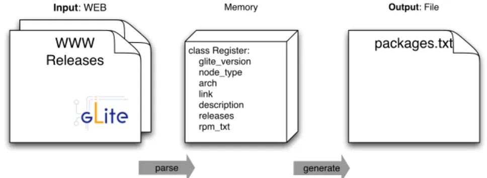
As part of this work, in order to aid administrators to obtain this list of RPMs, we created the gLite parser. This tool can be used to retrieve this list by parsing the gLite’s release pages3. gLite parser is a script that takes the version of the gLite middleware as a parameter and creates a folder tree structure where each folder represents a gLite meta-package. Inside each
2
YAIM is a configuration tool that executes the essential steps in order to prepare and configure the machine according to its role or appliance type. YAIM project website: http://yaim.info/
3
34 CHAPTER 3. USING THE CLUSTER TO SCALE THE GRID meta-package folder, other folders exist - one for each release - containing the RPM list in text form.
WWW
Releases class Register: glite_version node_type arch link description releases rpm_txt
Input: WEB Memory
packages.txt Output: File
parse generate
Figure 3.3: gLite parser workflow
As depicted in figure 3.3, the tool starts by parsing the releases web page for available meta-packages and then, for each one, parses its release page for released versions. For each version, the tool detects the list of the RPM packages that belong to this meta-package, and also any special information, such as if reconfiguration of the service provided by the meta-package is needed, or the priority level of this particular release.
The administrator can then use the desired meta-package/release to pass as argument when adding a new update, or to, for instance, retrieve all, or some, RPMs. This last option, is useful to recreate the EGI roll with the latest releases.
The parser, written in Python, is based on the HTML/XML parser BeautifulSoup4, designed for quick turnaround projects like screen-scraping. BeautifulSoup simplifies the parsing task by turning HTML into a navigable parse tree.
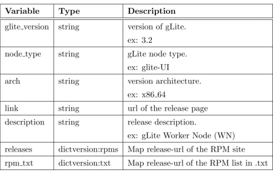
While parsing the HTML pages, the tool fills a data structure, composed by instances of the class Register (see table 3.1).
Although, this tool has some limitations because it is based on the HTML structure of the gLite releases page, which may change and break the existing code. At the time of writing, the site structure doesn’t fulfil the XHTML standards, making the parsing harder and leading to a more complicated code.
4
3.4. INTEGRATION 35
Variable Type Description
glite version string version of gLite.
ex: 3.2
node type string gLite node type.
ex: glite-UI
arch string version architecture.
ex: x86 64
link string url of the release page
description string release description.
ex: gLite Worker Node (WN) releases dictversion:rpms Map release-url of the RPM site rpm txt dictversion:txt Map release-url of the RPM list in .txt
Table 3.1: The class Register holds information about each gLite node.
3.4
Integration
The main goal of this study is to obtain an integrated management re-source that handles different computing mechanisms in an easy and seamless way.
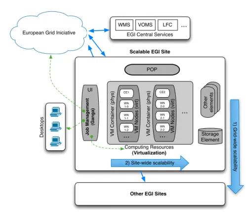
In order to join these technologies together, these dots have to be con-nected, filling the existing gap and creating a technology bridge as depicted in figure 3.4.
Every EGI site has to obey to certain rules, respecting the minimum requirements set by the project, and provide a set of control mechanisms. These components, also known as elements in gLite, are installed in different machines. As described in section 3.2, this is performed in an easier way using the Rocks Clusters mechanisms.
Traditionally, the structure of an EGI site is almost static, composed by a set of machines. This integration method allows the administrator to easily expand the computing resources, according to the needs, using virtualisation technologies. New clusters can be easily deployed without needing to modify the physical structure of the site, severely increasing its scalability.
36 CHAPTER 3. USING THE CLUSTER TO SCALE THE GRID
European Grid Iniciative EGI Central Services
WMS VOMS LFC
Scalable EGI Site
POP UI Computing Resources (Virtualization) Storage Element J o b Ma n a g e m e n t (G a n g a ) O th e r e le me n ts ... VM C o n ta in e r (p h ys) CE1 WN 1-0 WN 1-1 VM N o d e s (vi rt ) WN 1-2 ... VM C o n ta in e r (p h ys) CE2 WN 2-0 WN 2-1 VM N o d e s (vi rt ) WN 2-2 ... ... D e skt o p s
Other EGI Sites
1 ) G ri d -w id e sca la b ilit y 2) Site-wide scalability
Figure 3.4: EGI roll scalability.
scalability and flexibility of the system, to permit new institutions to rapidly integrate the project.
Summing up, the general ecosystem can easily scale in two different di-mensions. The first one, referred as Grid-wide, allows multiple sites to be efficiently deployed by using the mechanisms provided by Rocks Clusters and, more specifically, solutions like the EGI roll. The second vector, re-ferred as Site-wide, allows the site itself to grow within its boundaries, it terms of the services it provides. This idea is expressed in figure 3.4.
The Job Management software, described in section 2.4, is an important component of the platform that allows the user to easily run his jobs in dif-ferent environments using the same job description. More than just running the job, it permits monitoring the task, retrieving the outputs and selecting the destination.
Chapter 4
Connecting users across Grid
sites
Advanced computing infrastructures are complex environments where the user has limited interference. The user can choose between traditional infrastructures or several other options that don’t impose significant prior investments, such as the Grid, virtualised Clouds, and even by personal systems.
The User Domains platform, presented in [1] tries to leverage resources from multiple providers in an efficient user-level infrastructure overlay. The authors proposed the Domain abstraction to manage user-level computing capacity available in multiple sites. The resources are unified in a personal overlay infrastructure to allow the creation of consistent and flexible com-puter environments largely independent of any particular resource provider. This overlay is unique for each user and presents an interface system that mediates the connection between all the components of the system. In this context a Domain is a territory governed by a single ruler, it represents the computing elements the user has access to locally or in various resource providers.
However, NAT devices are in widespread use, so addressing the problem of accessing resources inside them is fundamental in a global access platform. We are currently evaluating SPM in more complex scenarios, measuring the interference of SPM in the Ethernet network overlay and in the disk block