A background-priority discrete boundary triangulation
method
Robert Edward Loke
IIT-CNR,Via Giuseppe Moruzzi 1, 56124 Pisa, Italy [email protected]
Frederik W. Jansen
Dept. of Mediamatics, EWI, Delft University of Technology,2600 GA, The Netherlands [email protected]
Hans du Buf
Vision Laboratory, FCT, University of Algarve, 8000 Faro, Portugal [email protected] ABSTRACTDiscrete boundary triangulation methods generate triangular meshes through the centers of the boundary voxels of a volumetric object. At some voxel configurations it may be arbitrary whether a part of the volume should be included in the object or could be classified as background. Consequently, important details such as concave and convex edges and corners are not consistently preserved in the describing geometry. We present a “background priority” version of an existing “object priority” algorithm [6]. We show that the ad hoc configurations of the well-known Discretized Marching Cubes algorithm [13] can be derived from our method and that a combined triangulation with “object priority” and “background priority” better would preserve object details. Keywords: Computer Graphics: Curve, surface, solid, and object representations; Computer aided design (modeling of curves and surfaces); Computational geometry; Image processing.
1
INTRODUCTION
Volume models consist of three-dimensional arrays of measured or computed values. Isosurfacing and other segmentation techniques are often applied to select ob-ject boundaries within a volume, which may then be converted into triangular meshes. The Marching Cubes algorithm [11], for instance, builds a triangle mesh through interpolation points between the centers of the discrete voxels. This gives an accurate isosurface but also leads to a large number of triangles. The Dis-cretized Marching Cube (DMC) method [13] constrains the interpolated positions to midpoints between voxel centers. This reduces the number of triangles and their possible orientations, which makes it easier to con-struct larger surface elements out of neighboring trian-gles with equal orientation. An alternative approach is to first segment the data, by thresholding or edge de-tection, into binary components and then to construct a surface through the centers of the boundary voxels of the discrete objects [6]. This method is fast and there-fore often used for previewing, without computing a more accurate surface construction. It has similar ad-vantages as the DMC method in that the number of tri-angles is strongly reduced compared to the exact inter-polation surface method. In fact, as we will see below, DMC can be seen as a special case of the “discrete”
Permission to make digital or hard copies of all or part of this work for personal or classroom use is granted without fee provided that copies are not made or distributed for profit or commercial advantage and that copies bear this notice and the full citation on the first page. To copy otherwise, or republish, to post on servers or to redistribute to lists, requires prior specific permission and/or a fee.
Short communication proceedings, ISBN 80-86943-05-4
WSCG’2006, January 30 – February 3, 2006
Plzen, Czech Republic.
Copyright UNION Agency – Science Press
surface method. In the following we equate the bound-ary consisting of only voxels with the surface model through the boundary voxel centers. We will call them both “discrete surface” in contrast to the “continuous” or “exact” surface that is interpolated between the voxel centers.
a
b
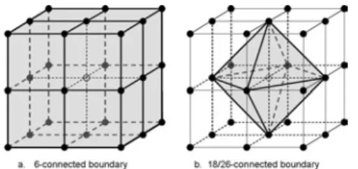
Figure 1: Object with 6-connected surface (a) and 18/26 connected surface (b)
As volume models are likely to become larger in the near future due to increased scanning and simulation resolutions (10243is a regular size nowadays), the dif-ferences in accuracy will diminish and a limited trian-gle count of the discrete models will become a major advantage.
Since the early seventies, quite some mathematical ingenuity has been invested in the study of boundary voxel configurations to find out under which condi-1
tions a discrete surface (consisting of only neighboring boundary voxels) has similar topological properties as a regular manifold surface model, i.e. correctly separates the interior from the exterior. This is relevant for thin-ning and skeletonization [4, 1, 15], ray casting volumet-ric objects [2, 5, 7], and surface construction [17, 16]. The study of these properties is known as digital topol-ogy [9, 8] and has resulted in several boundary def-initions by Morgenthaler and Rosenfeld [14], Malgo-uyres [12], Kovalevsky [10] and Couprie and Bertrand [3]. The latter introduced the notion of simplicity sur-face, which constitutes a boundary consisting of bound-ary points that are adjacent and are not simple points. Simple points are points that can be removed from the boundary without altering the topology. They give sev-eral operational definitions for simple points and they prove that a simplicity surface can be built out of only 8 different 2×2×2 voxel configurations [3]. On the ba-sis of these configurations it could be easy to define a boundary triangulation method.
However, the definition of simplicity surface is not of much value from a practical point of view, as we will see in Section 2. A more useful method was proposed by Kenmochi et al. [6] (below we refer to this method as the Kenmochi method). They define the boundary of a discrete solid as the boundary of the set of con-nected tetrahedra that constitute the volumetric object. To construct the boundary, the object is first decom-posed into a set of tetrahedra, and after removing the “double” surfaces shared by neighboring tetrahedra, the “single” outside faces constitute the overall boundary. They also presented a construction method that directly generates the composite boundary and deals with de-generated cases as dangling edges and folded surfaces.
The Kenmochi method is a sound and useful method. However, we can make an interesting observation: the method generates a surface with a maximum envelope, which is not in all cases desired. We will illustrate this issue by showing how the configurations of the Dis-cretized Marching Cubes (DMC) method [13] can be derived from the Kenmochi method. It will make clear that the Kenmochi method has some implicit assump-tions that do not in all cases give the expected and de-sired result. In Section 4, we propose an alternative triangulation scheme which is closer to the DMC con-figurations. But first, we start with an introduction on discrete surface representations.
2
DISCRETE SURFACE
REPRESEN-TATIONS
A volumetric representation consists of a three-dimensional grid of voxel cubes, where each voxel cube stores one or multiple values. We limit the discussion here to regular grids that constitute a discrete space with voxels that are either black (the object) or white (the background). Each voxel has
a 3×3×3 neighborhood with other voxels which are 26-adjacent to the central voxel from which 6 voxel centers have a Manhattan distance to the neighborhood center of one, 12 centers a distance of 2, and 8 centers a distance of 3 steps in orthogonal directions. This voxel neighborhood can be decomposed into 8 cuberille cells, see Figure 2; the figure shows the cuberilles between the voxel centers.
Figure 2: Adjacency relations
In the 3D example shown in Figure 3, the black points constitute a discrete object with only one interior point (marked gray) and 26 boundary points. If we define the boundary in terms of a set of 6-connected points, then we have 26 boundary points. If we also include 18- and 26-connectivity then the edge and corner points become “simple,” i.e. they do not longer border directly to the interior. The 26-surface would be only the octahedron around the interior point (Figure 3b), whereas the 6-surface would be the full cube (Figure 3a), what in most practical cases would be the desired result. Hence, if we want to maintain straight corners then we should elimi-nate the “short cuts”. However, if we have an oblique or curved surface, then we would like to use the diagonal short cuts of the 26-adjacency in order to avoid the stair-casing of the 6-surface representation (see Figure 1).
Figure 3: 3D example: 6-connected and 26-connected boundaries
Kenmochi circumvents this dilemma in her method by defining the boundary of the discrete object as the boundary of the set of discrete simplexes that consti-tute the object. In 2D the simplex is a triangle and in 3D a tetrahedron. If the 3D discrete object can be decomposed into a set of connected (non-degenerated) polyhedra, then its boundary is a manifold. This condi-tion excludes degenerated cases as dangling faces and edges, and other parts that are not properly connected to the main volume. The result of this definition is a sur-face that encloses the whole object volume and that is locally 6-connected and 18 or 26-connected in case of an oblique surface or a concave corner (see Figure 1b). 2
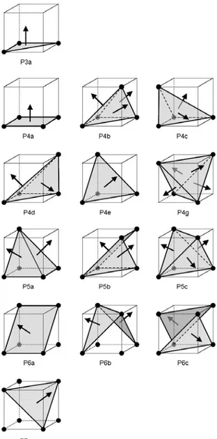
Kenmochi gives a slice-by-slice and cell-by-cell con-struction method that directly generates a correct sur-face using 14 triangulation patterns for 2×2×2 voxel configurations (Figure 5). The names of the configura-tions (P3a, etc.) are taken from [6].
Figure 4: Two different triangulation patterns for Ken-mochi configuration P6b, one with the middle tetrahe-dron (a) and one without (c)
Figure 5: Kenmochi configurations
Although the Kenmochi method maintains sharp cor-ners in case of convex configurations, it still gener-ates oblique faces in concave situations due to the fact
that the method generates tetrahedra in corners (see Figure 1b). If we want to avoid this we should give background points a higher priority than object points, and avoid the “short cuts” associated with 18 and 26-connectivity. However, then we also turn correctly in-terpolated oblique faces into staircases (Figure 1a), and the result would be equal to 6-connectivity only.
We may notice that the Kenmochi method in gen-eral gives priority to the object over the background, because it uses all possible tetrahedra between object points for its boundary definition. For instance in cell-configuration P6b, the middle tetrahedron (Figure 4b) can be arbitrarily assigned to the object or to the back-ground. If the central tetrahedron is removed we get an-other triangulation (compare Figure 4c with Figure 4a). This alternative triangulation may be useful in certain situations, as illustrated in Figures 14a and 15a.
The main problem is that we do not know a priori the shape of the real object before discretization, but it is clear that we may arbitrarily choose the one or the other configuration: “object over background” or “background over object” priority. To further exem-plify these issues we will take a closer look at the DMC method.
3
DISCRETIZED MARCHING CUBES
Montani et al. [13] presented their discretized version of the Marching Cubes algorithm as a method to re-duce the number of “pathological” cases prore-duced by the standard Marching Cubes algorithm. Instead of tak-ing the exact intersection of the isosurface with the edge between neighboring voxels, they take the midpoint. This increases the number of configurations from 14 in MC to 16 in DMC. We are in particular interested in their configurations “e,” “k,” “l,” “n,” “o” and “p” (see Figure 6).
It is not clear from [13] how these configurations were derived, but we may assume that they started by defining patterns for covering the faces of the cell (see Figure 7a, b, c and d), to guarantee continuity between cells. In addition, they selected the midpoint of the cell to be either in the object or not, and in case the midpoint is part of the object boundary, the midpoint is connected to the midpoints at the edges.
We may conclude that the authors of the DMC method gave priority to the background instead of the object, because otherwise the configurations would have been based on the face-configuration “7e” instead of “7c” (Figure 7). Of course, it is arbitrary whether we choose the one over the other and there is also no need to be consistent. The choice of whether the midpoint (in the DMC configurations) is part of the object is also arbitrary. For instance, the “DMC-e” configuration has five white corner points against three black, so it would be more natural to have the center point white, 3
Figure 6: Six of the 16 DMC configurations (cf. Figure 3 in Montani94)
Figure 7: DMC configurations can be derived from the above 2D patterns. It is arbitrary whether configuration c (background priority) is chosen or e (object priority) but a black center point generates a nice triangulation comparable to configuration “DMC-l”.
An alternative method to construct the DMC config-urations is to build them by using the Kenmochi algo-rithm. We do this by mapping the 2×2×2 DMC voxel configuration to a 3×3×3 voxel block. In the 3×3×3 block the DMC midpoints are now black and the other midpoints have the color of their neighboring corner points. We apply the configurations of Kenmochi (Fig-ure 5) to the eight individual 2×2×2 cells, and the re-sults are shown in Figure 8. We will notice some differ-ences with Figure 6.
In fact, as mentioned earlier, in the Kenmochi scheme the object has priority over the background, because it uses all possible tetrahedra between black points for its boundary definition. If we reverse the priority in the
Figure 8: The six DMC configurations derived with the Kenmochi method
DMC method, then the Kenmochi method will gener-ate a better approximation. However, there will still re-main small local differences due to the DMC construc-tion method, which connects the central point directly to the edge points.
In conclusion, we saw that DMC is a simplified ver-sion of a 3×3×3 surface construction with the restric-tion that the cell edges are only black-black, white-white, black-white or white-black voxel combinations (which is due to the 2×2×2 starting situation) and not white-black-white or black-white-black (which is only possible in the 3×3×3 configuration).
4
TRIANGULATION WITH
BACK-GROUND PRIORITY
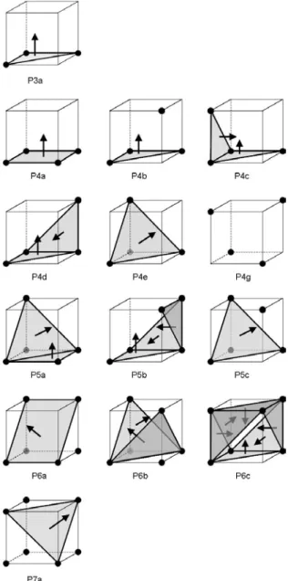
Looking at the above examples we may wonder whether there exists a triangulation that directly gener-ates the standard DMC configurations. This is indeed so (see Figure 9). Instead of using object priority (cf. Figure 7e) we follow the DMC convention (cf. Figure 7c) and give priority to the white diagonals. This means that object voxels are not 26-connected, but only 18-connected when they are 6-adjacent. Some of the Kenmochi configurations remain (P3a, P4a, P4e, P6a and P7a), whereas other configurations reduce to triangles or to combinations with dangling voxels 4
(P4b and P5c). P4g has no triangle anymore, only isolated points. The isolated points will have to be removed with a postprocessing similar to the removal of non-manifold situations in the Kenmochi method.
Figure 9: Background Priority scheme Now we can build the standard DMC configurations, see Figures 10 and 6, although there still remain some differences. This is because the triangulation using DMC configurations is done starting from the central point (if there is one). We can copy this by generat-ing an edge-list from the eight cells and then connect the edge corner points with the center point. This re-duces the number of triangles and makes the configura-tion smoother; compare “DMC-p” in Figures 6 and 10. In addition, if we introduce “don’t care” voxels then we can reduce the number of triangulation patterns to seven for the Kenmochi method and six for the Background Priority method (see Appendix).
Figure 10: The six DMC configurations with Back-ground Priority algorithm
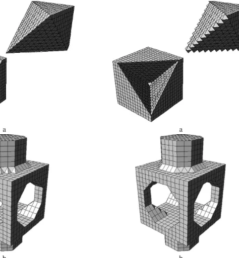
Figures 14 and 15 show results obtained with two test objects. Note that the sharp edges and the sharp corner of the cut-out part are correctly triangulated by the use of Kenmochi configurations P5c and P6b. However, in the cube where the cut-out part is taken from this is not the case. There, configuration P6b leads to aliasing at the sharp edges and configuration P7a to a cut-off of the sharp corner inside the cube. In the case of triangu-lations obtained with Background Priority the opposite effects are obtained, except for the sharp corner inside the cube, see below. The upper part of the Hoppe object obtained with the Background Priority method is better, whereas the bottom part is worse.
5
FUTURE RESEARCH
Obviously, the Kenmochi method should be used in order to triangulate convex boundaries and the Back-ground Priority to triangulate concave boundaries. In practice, we can check whether a voxel is at a convex or concave boundary by inspecting its 3×3×3 voxel neighborhood. Under normal conditions, when the number of voxels which belongs to the object in the neighborhood is larger than 18 the voxel in the center of the neighborhood is at a concave boundary. When the number is smaller than 18 the voxel in the center of the neighborhood is at a concave boundary. Figure 16 5
shows the results when we apply this triangulation strat-egy. As can be seen both convex and concave edges are better preserved. Since these results are promising, in the future we want to substitute the concave-convex heuristic by a robust algorithm which determines con-vexity or concavity in the local neighborhood and to topologically validate the combined triangulation ap-proach.
Figure 11 shows an alternative triangulation of pat-tern P7a which for oblique surfaces is not desired, but which in some cases, such as the sharp corner inside the cube in Figure 15a, better preserves the object detail. In order to decide which of the two triangulations must be applied it seems necessary to determine which ob-ject voxels belong to the boundary and which not. Also for some other configurations (e.g. P6a) other (extreme background priority) triangulations may be asked for in certain situations. These are important issues for future research.
Figure 11: Two possible triangulation patterns for Background Priority configuration P7a
ACKNOWLEDGEMENTS
The first author acknowledges the financial support pro-vided through the European Community’s Human Po-tential Programme under the contract HPRN-CT-2002-00278, Combinatorial Structure of Intractable Problems (COMBSTRU). This research is partly funded by the Portuguese FCT program POSI, framework QCA III.
APPENDIX
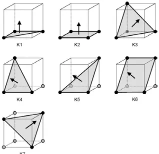
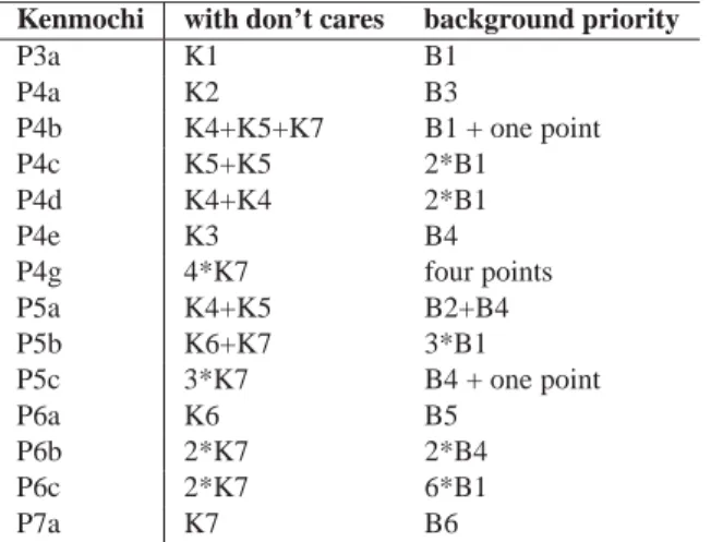
The triangulation patterns for the voxel configurations of Figures 5 and 9 can be built from a reduced set of basic triangulation patterns that use “don’t care” voxels for positions that can either be black or white. Figure 12 shows the basic patterns for the Kenmochi method and Figure 13 for the Background Priority method. We note that in each configuration of Figure 12 with “don’t cares” (K4-K7), at least one of the “don’t cares” must be black. For clarity, these patterns can be specified in ((((bottom-behind-left)-right)-fore)-top) order as:
K1: 1 1 1 0 0 0 0 0 K2: 1 1 1 1 0 0 0 0 K3: 1 1 1 0 1 0 0 0 K4: x x 1 1 1 0 0 0 K5: x x 1 1 0 1 0 0 K6: x x 1 1 1 1 0 0 K7: x x x 1 x 1 1 0 B1: 1 1 1 0 0 x x x B2: 1 1 1 1 0 0 0 1 B3: 1 1 1 1 0 0 0 0 B4: 1 1 1 x 1 0 0 x B5: 1 1 1 1 1 1 0 0 B6: 1 1 1 1 1 1 1 0,
where 0 denotes a white point, 1 a black one and x a “don’t care” case. Table 1 specifies the conversion.
Figure 12: Kenmochi method with “don’t care” voxels denoted in gray
Figure 13: Background Priority method with “don’t care” voxels denoted in gray
REFERENCES
[1] C. Arcelli and G. Sanniti di Baja. Skeletons of planar patterns. In T. Y. Kong and A. Rosenfeld, editors, Topological Algorithms
for Digital Image Processing, pages 99–143. Elsevier, 1996.
[2] D. Cohen-Or, A. E. Kaufman, and T. Y. Kong. On the sound-ness of surface voxelizations. In T. Y. Kong and A. Rosenfeld, editors, Topological Algorithms for Digital Image Processing, pages 181–204. Elsevier, 1996.
[3] M. Couprie and G. Bertrand. Simplicity surfaces: a new def-inition of surfaces in Z3. In Proc. SPIE Vision Geometry VII,
volume 3454, pages 40–51, 1998.
[4] R. Hall, T. Y. Kong, and A. Rosenfeld. Shrinking binary images. In T. Y. Kong and A. Rosenfeld, editors, Topological Algorithms
for Digital Image Processing, pages 31–98. Elsevier, 1996. 6
a
b
Figure 14: Triangulation with the Kenmochi method of a cube with cut-out part (a) and a Hoppe object (b)
[5] A. Kaufman. Volume Visualization. IEEE Computer Society Press Tutorial, Los Alamitos (CA), USA, 1991.
[6] Y. Kenmochi, A. Imiya, and A. Ichikawa. Boundary extraction of discrete objects. Computer Vision and Image Understanding, 71(3):281–293, 1998.
[7] A. Kodosh, D. Cohen-Or, and R. Yagel. Tricubic interpolation of discrete surfaces for binary volumes. IEEE Trans. Visual.
Comput. Graphics, 9(4):580–586, 2003.
[8] T. Y. Kong and A. Rosenfeld. Digital topology: introduction and survey. Comp. Vision, Graphics and Image Proc., 48:357– 393, 1989.
[9] T. Y. Kong and A. Rosenfeld. Topological Algorithms for
Digi-tal Image Processing. Elsevier, 1996.
[10] V. A. Kovalevsky. Finite topology as applied to image analysis.
Comp. Vision, Graphics and Image Proc., 46:141–161, 1989.
[11] W. E. Lorensen and H. E. Cline. Marching cubes: A high reso-lution 3D surface construction algorithm. Computer Graphics, 21(4):163–169, 1987.
[12] R. Malgouyres and G. Bertrand. Complete local characteriza-tion of strong surfaces: continuous analog for strong 26-surfaces. Int. Journal on Pattern Recognition and Artificial
In-telligence, 13(4):465–484, 1999.
[13] C. Montani, R. Scateni, and R. Scopigno. Discretized marching cubes. In R. D. Bergeron and A. E. Kaufman, editors, Proc.
Vi-sualization ’94, pages 281–287, Washington D.C., USA, 1994.
[14] D. G. Morgenthaler and A. Rosenfeld. Surfaces in three-dimensional digital images. Information and Control, 51:227–
a
b
Figure 15: Triangulation with the Background Priority method
247, 1981.
[15] K. Palágyi and A. Kuba. A 3D 6-subiteration thinning algo-rithm for extracting medial lines. Pattern Recognition Letters, 19:613–627, 1998.
[16] J. K. Udupa. Multidimensional digital boundaries. CVGIP:
Graphical Models and Image Processing, 56(4):311–323,
1994.
[17] J. K. Udupa. Connected, oriented, closed boundaries in digital spaces: Theory and algorithms. In T. Y. Kong and A. Rosenfeld, editors, Topological Algorithms for Digital Image Processing, pages 205–231. Elsevier, 1996.
a
b
Figure 16: Triangulation with the Kenmochi method at convex boundaries and the Background Priority method at concave boundaries
Table 1: Triangle lookup table for the Kenmochi algo-rithm with “don’t cares” and for the Background Priority algorithm
Kenmochi with don’t cares background priority
P3a K1 B1 P4a K2 B3 P4b K4+K5+K7 B1 + one point P4c K5+K5 2*B1 P4d K4+K4 2*B1 P4e K3 B4 P4g 4*K7 four points P5a K4+K5 B2+B4 P5b K6+K7 3*B1 P5c 3*K7 B4 + one point P6a K6 B5 P6b 2*K7 2*B4 P6c 2*K7 6*B1 P7a K7 B6 8